
Bussmann Relay Box. Could some check my thought process?

Ok, one final question. When you say dimmable, you mean these switches will only light up when the dash lights are on right? They will be off otherwise?

Thank you so much for all of your help!

no, when I say "dimmable" I mean at night when your dash is lit up you can manually adjust the brightness of the switch backlighting with the rheostat to the left of your steering wheel.... if you want this feature in your new switches, wire the right side of the OTTRATW switch to be dimmable. If not, wire it as not dimmable.
 
no, when I say "dimmable" I mean at night when your dash is lit up you can manually adjust the brightness of the switch backlighting with the rheostat to the left of your steering wheel.... if you want this feature in your new switches, wire the right side of the OTTRATW switch to be dimmable. If not, wire it as not dimmable.

Ah I see now. Thank you. Dimmable sounds nice if the bottom light is always on. Thanks again!
 
I'd recommend changing your switching logic to switch the ground to the relay. Then any shorts in the wire to the switch just turn the accessory on like normal, instead of putting 12V (that's hopefully fused) into the ground plane and then (hopefully just) blowing the fuse.

I used a Bussmann relay box to redo all the power distribution for my S13's engine and used this method.

I would also recommend making the whole box pull out of the car via a series of connectors. You can get some high pin count Metripack 280's that'll handle the current (if it's over the limit, just use two pins especially if it's a high duty cycle load to give it some more headroom on pin current).

The seals for the relay box are common between Weatherpack and Metripak 280 connectors as well.
 
I'd recommend changing your switching logic to switch the ground to the relay. Then any shorts in the wire to the switch just turn the accessory on like normal, instead of putting 12V (that's hopefully fused) into the ground plane and then (hopefully just) blowing the fuse.

I used a Bussmann relay box to redo all the power distribution for my S13's engine and used this method.

I would also recommend making the whole box pull out of the car via a series of connectors. You can get some high pin count Metripack 280's that'll handle the current (if it's over the limit, just use two pins especially if it's a high duty cycle load to give it some more headroom on pin current).

The seals for the relay box are common between Weatherpack and Metripak 280 connectors as well.

Ok, the quick disconnects don't sound like a bad idea at all. Maybe I'll make a quick disconnect for each set of two wires coming out (Switch and Acc wires).

Could you go into a little more detail on the first thing you talked about? Electrical is definitely not my strong suit yet. When you say switch the ground to the relay, do you mean send the ground wire from the relay to the switch itself, or am I completely missing the point? Thanks!
 
It looks like you've got a 12V live ciruit going out to the switch, which is then switched, and goes to the 12V switching terminal of the relay.

What you can do is run that 12V line to the relay 12V terminal permanently (either always on or ignition switched via another relay signal - there are lots of 12V switched signals to pull from, and switching a relay uses like 10-40 mA, basically nothing). Then you take the ground line off the relay's ground switched terminal and then run it to a ground right by the switch.

Not only does this basically halve the wiring to the switch (no need to go back to the box, just ground to the body right at the switch location), but if it does get a short in it, it'll just turn the circuit on with no excessive current usage if it shorts like it would before the relay switching coil.

I used a 5 pin and a 6 pin Metripack 280 connector for mine I believe. You can find complete sets with seals and pins on eBay for about $6-8/ea so you don't have to buy 100 of each piece. It is way cheaper if you're just going to use a few connectors.
 
It looks like you've got a 12V live ciruit going out to the switch, which is then switched, and goes to the 12V switching terminal of the relay.

What you can do is run that 12V line to the relay 12V terminal permanently (either always on or ignition switched via another relay signal - there are lots of 12V switched signals to pull from, and switching a relay uses like 10-40 mA, basically nothing). Then you take the ground line off the relay's ground switched terminal and then run it to a ground right by the switch.

Not only does this basically halve the wiring to the switch (no need to go back to the box, just ground to the body right at the switch location), but if it does get a short in it, it'll just turn the circuit on with no excessive current usage if it shorts like it would before the relay switching coil.

I used a 5 pin and a 6 pin Metripack 280 connector for mine I believe. You can find complete sets with seals and pins on eBay for about $6-8/ea so you don't have to buy 100 of each piece. It is way cheaper if you're just going to use a few connectors.

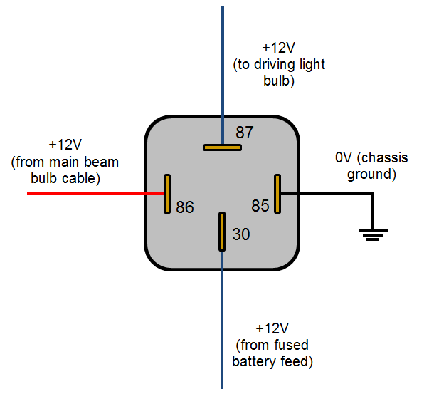
Ok, I'm honestly having a really hard time visualizing what you mean. Sorry. Would you be able to draw a diagram? If not, I completely understand, but what you are saying just isn't clicking right now. Maybe I'm just being super dumb? Idk.
 
Driving_light_relay_wiring_diagram.png


You are currently switching pin 86 with a line 12V line going to and from a switch.

Connect up 86 with the 12V wire, then put your switch in between pin 85 and the chassis ground (which can be right by the switch).

Read over my explanations above, it should make sense why I say to do this.
 
Driving_light_relay_wiring_diagram.png


You are currently switching pin 86 with a line 12V line going to and from a switch.

Connect up 86 with the 12V wire, then put your switch in between pin 85 and the chassis ground (which can be right by the switch).

Read over my explanations above, it should make sense why I say to do this.

Ok so let me see if I have this straight. I have the fused buss going to pin 30. I have the ground buss going to pin 85. Pin 87 is the thicker wiring heading to Acc in my diagram. And pin 86 is the control pin that is going out to the switch as well (labeled in the diagram). I am kinda confused as to where you are getting the 12V. Are you talking about the "Constant 12V" wire going out to the left from my diagram? If so, then are you saying I shouldn't run that wire, but rather run the grounds to the pin on the switch so that when I turn the switch on, it completes the ground? Wouldn't that mean my switch LEDs also don't light up anymore?
 
If your switch needs power, then provide it with power. Typically lighted switches have 3 pins, and you can power the light via 12V direct to it.

I was just providing a suggestion on the safer way of doing things, but it might not work for your specific case for whatever reason. You're designing an automotive circuit that COULD burn your vehicle down if you get it really wrong and have a 12V battery fed, non-fused circuit grounding out somewhere.


So I'll leave with saying, do lots and lots of studying, then make smart choices on how to design everything.
 
If your switch needs power, then provide it with power. Typically lighted switches have 3 pins, and you can power the light via 12V direct to it.

I was just providing a suggestion on the safer way of doing things, but it might not work for your specific case for whatever reason. You're designing an automotive circuit that COULD burn your vehicle down if you get it really wrong and have a 12V battery fed, non-fused circuit grounding out somewhere.


So I'll leave with saying, do lots and lots of studying, then make smart choices on how to design everything.

Well all of the connections coming out of the box will be fused. Even that 12V constant wire. And there is an 80A fuse between the battery and box as a whole. But I really appreciate it. I will definitely keep doing my homework!
 
[MENTION=87178]NuclearN8[/MENTION] Ok I have one last question for you. Let's say I wanted to run one of the non-relayed wires with a switch. Say the CB radio in my diagram. How would I go about wiring that? Just curious.
 
Two things:

1. A 15 A fuse needs way more than an 18 Ga wire. Probably more like a 16-14 Ga wire.

2. Why would you not run a relay with it? The whole point of relays is to switch very low current loads so the switched 12V can be run off a simple 5-10 A fuse for all of them for safety, and a low gauge wire on all of them.

When you start switching high amp loads (>2-3 A) directly with a switch, you are losing the benefit of a relay'd circuit.
 
Two things:

1. A 15 A fuse needs way more than an 18 Ga wire. Probably more like a 16-14 Ga wire.

2. Why would you not run a relay with it? The whole point of relays is to switch very low current loads so the switched 12V can be run off a simple 5-10 A fuse for all of them for safety, and a low gauge wire on all of them.

When you start switching high amp loads (>2-3 A) directly with a switch, you are losing the benefit of a relay'd circuit.

1. Yea I know. All of the non-fused wiring is "up in the air" right now, as are the size of the fuses. For example, that CB radio fuse is likely going to be 7.5A with 16Ga wiring.

2. If you are talking about the CB radio, I would say I wouldn't run a relay because A) I already run it without one and it has been fine, and B) I am trying to keep all my relays in this box, and I have plans for all 5 already.
 
[MENTION=87178]NuclearN8[/MENTION] Ok I have one last question for you. Let's say I wanted to run one of the non-relayed wires with a switch. Say the CB radio in my diagram. How would I go about wiring that? Just curious.

It seems like you're answering your own question. No relay, but a switch. All SPST swtiches like the OTTRATTW that you're using have 3 prongs on the left side. the to relay is the output of the switch so just wire that prong to the CB and when the switch is closed, the CB will have power from the power supply prong.
 
It seems like you're answering your own question. No relay, but a switch. All SPST swtiches like the OTTRATTW that you're using have 3 prongs on the left side. the to relay is the output of the switch so just wire that prong to the CB and when the switch is closed, the CB will have power from the power supply prong.

That's what I thought. Thanks again!
 

Members online

Forum statistics

Threads
278,312
Messages
3,554,089
Members
248,016
Latest member
Advally Service

Trending content

Back
Top