Consolidated Lighting Info Thread

64d54fcf472517e31d9aef64e3665b14.jpg


If this drawing is confusing, I can redraw

Looks like the black wire from the harness is not needed as it already has a ground on the relay side. Should be able to fold it back and tape it up.

EDITED AFTER RECENT DRAWING: Looking at the diagram & your description of connections, I cannot see why the switch would illuminate with the switch off and go off when you turn on the ignition.

I wonder if 2 pins on the AOB switch (illumination side) are in the wrong position!

Maybe [MENTION=83083]rigtec[/MENTION] can shed some light. (no pun intended)
 
Last edited:
Wait...what?


Nothing connected to #30?

See the difference in the terminal connections?

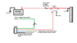
196154d1458356165-2014-2016-behind-grill-light-bar-mounts-aux-light-wiring.png


I'm going to look at that tomorrow.. I could have sworn the red wire in the cab was wired to it... maybe when the relay is plugged up ... that's why I mis drew the diagram the first time. I appreciate you getting back to me man. I'd go out there now but my wife is sick and doing dinner for kiddos ..


Sent from my iPhone using Tapatalk
 
So I thought I had it figured out, I got the led light switch portion wired in and switch turns on light and off ( red wire on aob switch to blue wire on rigid harness.. green w/yellow stripe on aob switch to red wire on rigid harness , black wire from rigid harness is not hooked to anything... maybe it should ??
2546e799686e854bc0881e33eca8b6da.jpg
511848f697d1fd29a9016639e2de40e4.jpg
)
I believe the black and blue w/ yellow stripe are for illumination of switch when truck is running / lights on. Problem is that the light on aob switch is on when truck / lights are off and cuts off when I crank the truck or turn lights off ?? It's like it's backwards ?
I have black wire from aob switch spliced into Grey wire on wiper heater and blue w/ yellow stripe from aob switch spliced into green on wiper heater.. can anyone give me some guidance? I have some experience with 120v AC switches
and wiring , but absolutely NONE on DC voltage and I still have yet to wrap my brain around it :/


Sent from my iPhone using Tapatalk


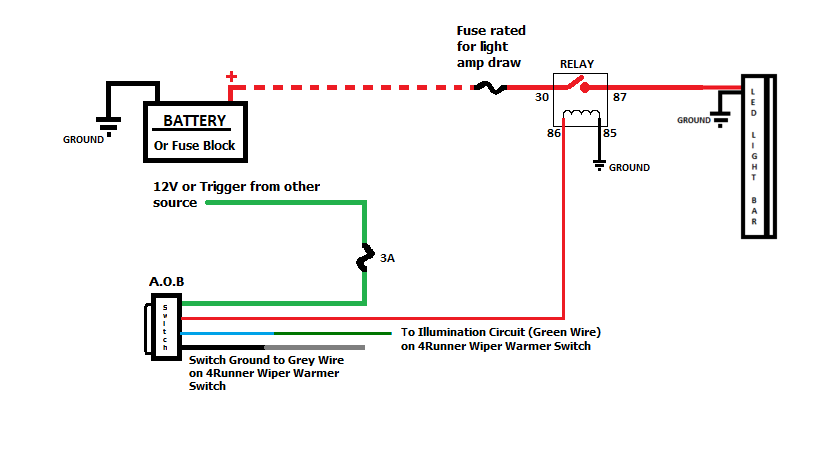
I think you need to get the red wire(harness)/green wire(switch) connected to your headlights or high beams. Hard to diagnose these things remotely but it would account for your symptoms with the switch lights. Terminals 30 and 87 are for power to the light bar only. Follow the diagram provided above or read sakers light bar install thread. Good luck dude, one minor tweak and I for one would like to see pics of the final results.
 
Last edited:
"...Maybe [MENTION=83083]rigtec[/MENTION] can shed some light. (no pun intended)"

Hi folks...

I've taken a strong glance at this entire thread, and the one thing that I was looking for is for someone to acknowledge the Courtesy circuit's Illumination source POS Green and NEG Gray; which initiates the illuminated dash switches when the parking lights are on! Your BLUE wire on the AOB switch is for illuminating the etched switch face. The GRAY wire in-dash on the other illuminated switches (NEG- variable ground) goes to the dimmer dial on the dash (via the MB-ECU). If you wire it that way it will work as it should... 'Best to you all',

rig


Last edited:
Opps...

Mr. [MENTION=103267]Saker[/MENTION] did illustrate the proper wiring of the illumination circuit on his very last post; Kudos Keith! ...and happy holidays!

Greg
 
[MENTION=6487]trdtim[/MENTION]...as [MENTION=83083]rigtec[/MENTION] and [MENTION=103267]Saker[/MENTION] said above...should be good to go. The ground from the rigid harness (black wire) is not needed because you tapped the factory grey in the other switch with your AOB ground. You should be able to just tape it off and call it a day.
 
[MENTION=6487]trdtim[/MENTION]...as [MENTION=83083]rigtec[/MENTION] and [MENTION=103267]Saker[/MENTION] said above...should be good to go. The ground from the rigid harness (black wire) is not needed because you tapped the factory grey in the other switch with your AOB ground. You should be able to just tape it off and call it a day.

Hi Cymon,

Remember... He will still need the large Black cable (BLACK) from the Light-bar to ground the Light-bar to the battery NEG post; but you're right, he won't need to use the small black wire to ground the switch in-dash provided he's grounding at the (Gray wire) 'dimmer dial' in the dash! ...good call!

rig
 
he won't need to use the small black wire to ground the switch in-dash provided he's grounding at the (Gray wire) 'dimmer dial' in the dash!

The only thing I do not like in the diagram is that AOB switch has LED between Red (Output to relay) and Black (connected to grey-dimmer). The reason I don't like in it is that this LED will be drained to grey (dimmer) when the switch is ON even when car's lights are OFF. Normally the dimmer works only when truck's lights are ON so introducing current to the dimmer circuit when lights are OFF makes it work not as designed by Toyota.

Now the good thing is that many proved that dimmer somehow works even when the truck's lights ore OFF so everything is OK, and the combination meter assembly (dimmer circuit is in there) survives such unexpected connection. So all is cool.

I just wish that AOB would use additional wire for grounding the LED connected to Red wire (LED indicating that the switch is in ON position). Stock Toyota switches have exactly that (all switches with green LED indicating that the switch is ON have 5 connectors).

This is exactly what I did to AOB switch for my rear fog lights. The switch ON indication LED is always "full blast" regardless of the dimmer position as I have "grey" wire and ground connected to the switch (grey wire is for switch back-light, ground is for indication of ON position). http://www.toyota-4runner.org/2436976-post12.html
 
Sorry , been out of pocket this week had to go out of town last minute for work and just getting back. I'm going to look at it tonight when I get home. So far I am gathering I need to take my black wire coming from LED harness and put to my battery ground ( or frame ? ) . The rest I'm still confused about. [emoji51]


Sent from my iPhone using Tapatalk
 
..........So far I am gathering I need to take my black wire coming from LED harness and put to my battery ground ( or frame ? ) . The rest I'm still confused about.

[MENTION=136811]trd tim[/MENTION],

First, you have posted confusing diagrams.

You need to post an accurate relay connection diagram with all connections and wire colors. This will clear up the other 2 or 3 !

You also should read the previous post as to what to do with the black wire that is leaving the harness. Exception to the black wire is if it is not tied into the relay already.
 
Just got off the phone with Alex at Rigid and he said 30 on the relay is not used. Red is 12v constant, blue is signal out to the light and black is ground. Basically touching red to blue will cut on led light but will also pull up to 10amps... he said he didn't see a way to use a 3amp switch with the rigid harness ?


Sent from my iPhone using Tapatalk
 
The only thing I do not like in the diagram is that AOB switch has LED between Red (Output to relay) and Black (connected to grey-dimmer). The reason I don't like in it is that this LED will be drained to grey (dimmer) when the switch is ON even when car's lights are OFF. Normally the dimmer works only when truck's lights are ON so introducing current to the dimmer circuit when lights are OFF makes it work not as designed by Toyota.


Now the good thing is that many proved that dimmer somehow works even when the truck's lights ore OFF so everything is OK, and the combination meter assembly (dimmer circuit is in there) survives such unexpected connection. So all is cool.


I just wish that AOB would use additional wire for grounding the LED connected to Red wire (LED indicating that the switch is in ON position). Stock Toyota switches have exactly that (all switches with green LED indicating that the switch is ON have 5 connectors).


This is exactly what I did to AOB switch for my rear fog lights. The switch ON indication LED is always "full blast" regardless of the dimmer position as I have "grey" wire and ground connected to the switch (grey wire is for switch back-light, ground is for indication of ON position). http://www.toyota-4runner.org/2436976-post12.html


That link isn't working ?


Sent from my iPhone using Tapatalk
 
Just got off the phone with Alex at Rigid and he said 30 on the relay is not used. Red is 12v constant, blue is signal out to the light and black is ground. Basically touching red to blue will cut on led light but will also pull up to 10amps... he said he didn't see a way to use a 3amp switch with the rigid harness ?

Ok, the statement you said came from Rigid is confusing also. Why even use a relay if the side of the relay to be used with a switch is not being used.
That would place the full load of the light bar thru the switch and that is not how things are done with the use of a relay!

I would strongly advise, you or get someone to do the following ..................... look at what you currently have and re-position or remake the harness to the proper relay connections so (just like everyone else) you can use and light your LED bar properly with a relay, harness and light switch!
 
I was hoping not to have to cut open that harness , but looking like it's unavoidable. When I asked them for a schematic on the harness he said he didn't have that and they get them prewired from another party. When I asked for that party's info, he said if I wanted to call China. I gave up at that point. The rigid lighted switch is rated at 30 or 40 amps. So it doesn't surprise me that full load runs thru. It does surprise me that I don't see more guys on here that have run into the Rigid harness to AOB switch issue.


Sent from my iPhone using Tapatalk
 
Pin 30 is used, has to be. If I were you I would start over and wire like this..
 

Attachments

  • LED.png
    LED.png
    20.7 KB · Views: 828
I was hoping not to have to cut open that harness , but looking like it's unavoidable.
You may or may not have to cut into the harness. Just look at the connections at the harness, document where they go to the relay. Follow proper wiring diagram to use the proper terminals on the relay. Currently (if what you say is true from Rigid) you are by-passing the trigger or coil circuit on the relay, which is absurd. Why even have the relay there. One reason for a relay is so you do not have to have the full load running thru the switch.

When I asked them for a schematic on the harness he said he didn't have that and they get them prewired from another party. When I asked for that party's info, he said if I wanted to call China. I gave up at that point.
I cannot understand why Rigid would not have that info.

The rigid lighted switch is rated at 30 or 40 amps. So it doesn't surprise me that full load runs thru.
Again, this is absurd to run full power thru a switch, especially if that harness has a relay on the other end.....that does not make sense. Period!

It does surprise me that I don't see more guys on here that have run into the Rigid harness to AOB switch issue.
Maybe, they just have not looked here to respond, or they did not have an issue.

You could always replace your harness with a quality harness made by yourself or look at the following link and obtain a harness w/ relay referenced in my write-up.
http://www.toyota-4runner.org/5th-gen-t4rs/164966-led-light-bar-install-2014-toyota-4runner.html
 

Members online

No members online now.

Forum statistics

Threads
278,310
Messages
3,554,078
Members
248,016
Latest member
Advally Service

Trending content

Back
Top