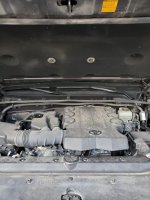
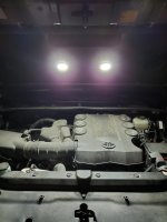
Engine compartment light mod

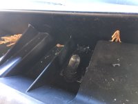
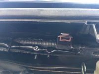
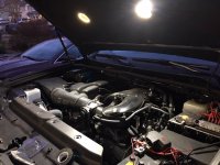
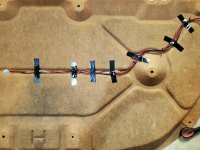
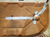
I used two KC hilites under the hood and used a waterproof on/off switch mounted on the cowl
 

Attachments

  • switch1.JPG
    switch1.JPG
    77 KB · Views: 717
  • switch2.JPG
    switch2.JPG
    80.8 KB · Views: 705
  • underhood lights2.JPG
    underhood lights2.JPG
    124.6 KB · Views: 706
  • underhood lights1.JPG
    underhood lights1.JPG
    115.8 KB · Views: 725
I did a similar install with the pin switch on an 04 Maxima I had. I guess I'll be doing another one soon. Thanks to everyone who contributed info to this thread.
 
So after purchasing the 2021 TRDORP I did an updated Engine Compartment Light Mod on
November 18, 2020, just didn’t post it here.

po4w3lOHj


pobfCqKLj


pmgdxlEYj


pmNCz8L8j


pmYS1Av1j


No Ambient Light Source
po8HbjR6j
 
That's really cool, if I didn't have mine wired into my sPod I definitely would go for that gas prop switch

I had the pin switch and it was garbage, started to rust and not turn on when it was engaged
 
So after purchasing the 2021 TRDORP I did an updated Engine Compartment Light Mod on
November 18, 2020, just didn’t post it here.

No Ambient Light Source
po8HbjR6j


This is really cool. Would it be possible for you to do a write-up of how you did this?

I do not have electrical experience so I don't even know where to begin.
 
po4w3lOHj


pobfCqKLj


pmgdxlEYj


pmNCz8L8j


pmYS1Av1j


No Ambient Light Source
po8HbjR6j

This is really cool. Would it be possible for you to do a write-up of how you did this?

I do not have electrical experience so I don't even know where to begin.

So, I’ll try to help.

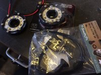
Look up and order the items you see in the photos.
You will also need some 18 or 16 gauge red and black wire.
Butt splices for purchased wire size.
Heat shrink tubing to insulate/waterproof the butt connectors.
Split wire loom to cover your wiring.

Measure your LED strip after figuring out exactly where you want it at the forward underside portion of the hood. Cut LED strip to length.
Figure out how you want to run your wire, install prop switch
Solder or butt splice the red & black wires to your LED strip. Heat shrink your connectors.
Install the LED strip, rough run wires keeping in mind not to position them when you close the hood!
You will want the black wire to to be run to a common ground under the hood.
You will butt connect the red wire to one wire on the prop switch. Connect another red wire to the other prop switch and run it to a power source that is fused with a 2 or 3 amp fuse.
You need to heat shrink the butt connectors.
Install wire loom to make it look clean and factory.

 
So, I’ll try to help.

Look up and order the items you see in the photos.
You will also need some 18 or 16 gauge red and black wire.
Butt splices for purchased wire size.
Heat shrink tubing to insulate/waterproof the butt connectors.
Split wire loom to cover your wiring.

Measure your LED strip after figuring out exactly where you want it at the forward underside portion of the hood. Cut LED strip to length.
Figure out how you want to run your wire, install prop switch
Solder or butt splice the red & black wires to your LED strip. Heat shrink your connectors.
Install the LED strip, rough run wires keeping in mind not to position them when you close the hood!
You will want the black wire to to be run to a common ground under the hood.
You will butt connect the red wire to one wire on the prop switch. Connect another red wire to the other prop switch and run it to a power source that is fused with a 2 or 3 amp fuse.
You need to heat shrink the butt connectors.
Install wire loom to make it look clean and factory.

This is very helpful, thank you.

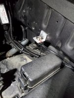
In regards to the power source, I see the little assembly with fuses in your pictures. Is it this aux power kit you used?

Toyota 4Runner - Complete Auxiliary Power Kit (2010-2019) – Overland Equipped
 
Got mine done tonight - with only parts I already had on hand. (Pic taken in a completely dark garage (besides the (green, which is actually a black light bulb) bug zapper light)

5da0ae0342ed0dc1d530bafec7f55979.jpg


Sent from my iPhone using Tapatalk Pro
 
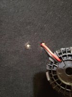
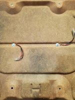
Attached mine to the insulator because I didn't want to drill any holes. As you can see there are grooves in the back deep enough for a nut and washer. Does not make contact with the metal. Great place to run the wires as well.
 

Attachments

  • 1.jpg
    1.jpg
    133.3 KB · Views: 271
  • 2.jpg
    2.jpg
    127.8 KB · Views: 264
  • 3.jpg
    3.jpg
    137.5 KB · Views: 264
  • 4.jpg
    4.jpg
    135.7 KB · Views: 282
  • 5.jpg
    5.jpg
    136.6 KB · Views: 276
  • 6.jpg
    6.jpg
    134.6 KB · Views: 263
  • 7.jpg
    7.jpg
    130.4 KB · Views: 283

Members online

No members online now.

Forum statistics

Threads
278,306
Messages
3,554,045
Members
248,016
Latest member
Advally Service

Trending content

Back
Top