
Parts:
ARB CKMA12 Compressor 9 lbs
Custom Mounting Plate
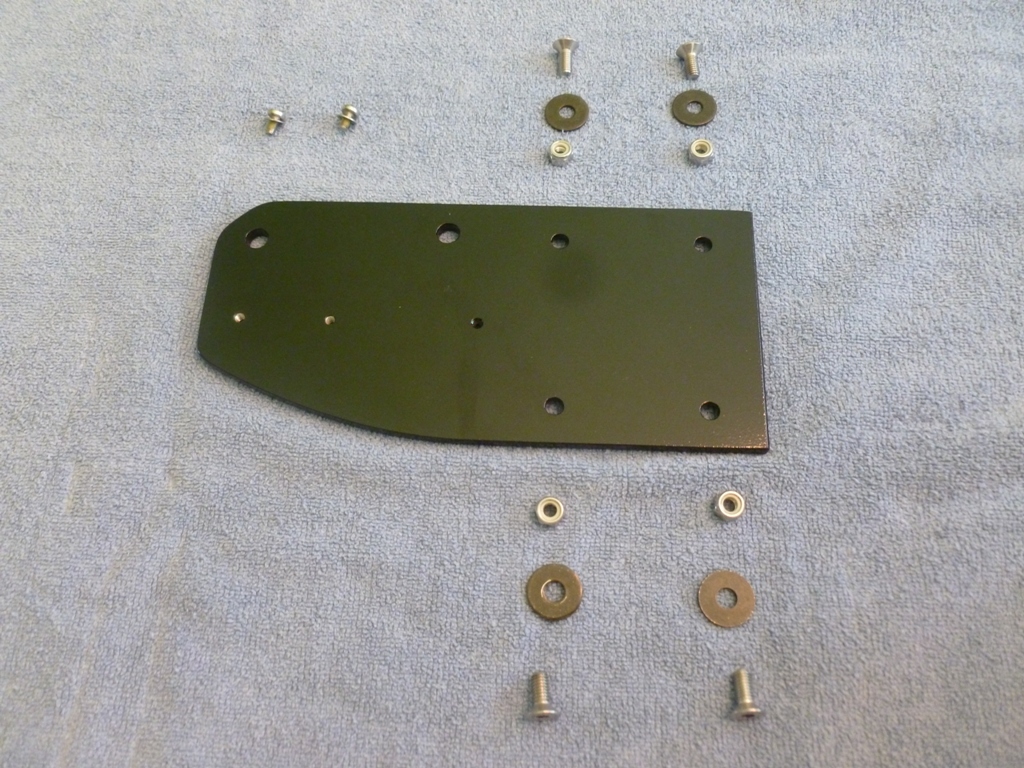
Hardware: qty:4 M6 x 12mm Flathead Socket head Stainless, qty:4 M6 Washer from ARB kit, qty:4 M6 nylon insert locknut, qty:1 M4 x 6mm Panhead stainless, qty:1 M4 flat washer stainless, qty:2 M8 bolts to mount to the body
ARB Tire Inflation Kit
Reason for Install:
Airing down has considerable benefits on almost all off road surfaces. Airing back up to regular pressures, however, is critical for safe driving at highway speeds. My requirements for a compressor were as follows:
-Air up 4 tires up to 35" within a single duty cycle
-All parts (compressor, tank, regulator, fittings, etc.) must fit in a sensible location
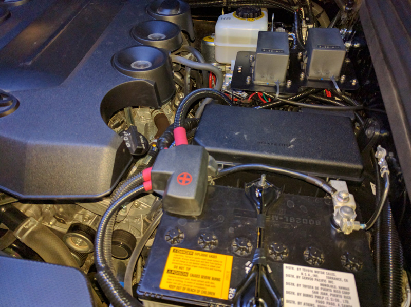
I spent way too much time researching compressors from possibly all available brands. There are awesome compressors out there like the ExtremeAir 007-000 which has a continuous duty cycle. I thought it would be good to mount it in between the passenger side frame rail and slider but a) it is just too large to fit in that location and b) it isn't fully submersible just in case I ford some water. That one also needs to add a tank, regulator, pressure switch, etc. which was just too much effort for something that would likely not fit anywhere I liked without major modifications to the 4Runner. In fact, I couldn't find a reasonably priced yet submersible compressor so my mounting options were somewhere in the cabin or under the hood. Engine heat soak will shorten the duty cycle of most compressors mounted under the hood. However, mounting in the cabin can get pretty annoying. I settled on the CKMA12 because it is a very compact package that contains a 50% duty cycle motor, a reservoir, regulator, pressure switch, wiring harness, and the ability to add on air locker solenoids (if I ever want to put on a front diff locker). After receiving the compressor, taking it apart, inspecting the build quality and design, I've become an ARB fanboy. It takes a lot to impress me when it comes to mechanical design of consumer products as well as documentation and user manuals, but this appears to be a very high quality product. So far I haven't heard of any major negative experiences with this compressor. The compactness of the CKMA12 affords installation near the master cylinder and fuse box so I chose that location for a few reasons:
-It doesn't get direct heat from the headers
-It is easy to access, clean, replace filter, inspect for leaks, etc.
-I plan to put a 2nd battery behind the wheel well arch on the passenger side since I have a smog pump (2013+)
-Making a mounting bracket was pretty easy and cheap
The only thing I don't really like about this bracket design is that it is a cantilever beam and is subject to vibration modes. Given that the compressor vibrates itself like crazy and is mounted on vibration damping legs, I've convinced myself it will be ok. In practice, the .250" plate is more rigid than the body to which it is mounted.
I haven't noticed any EMF effects on neighboring circuitry from the motor so far therefore I think the location is decent.
Now for the custom bracket.
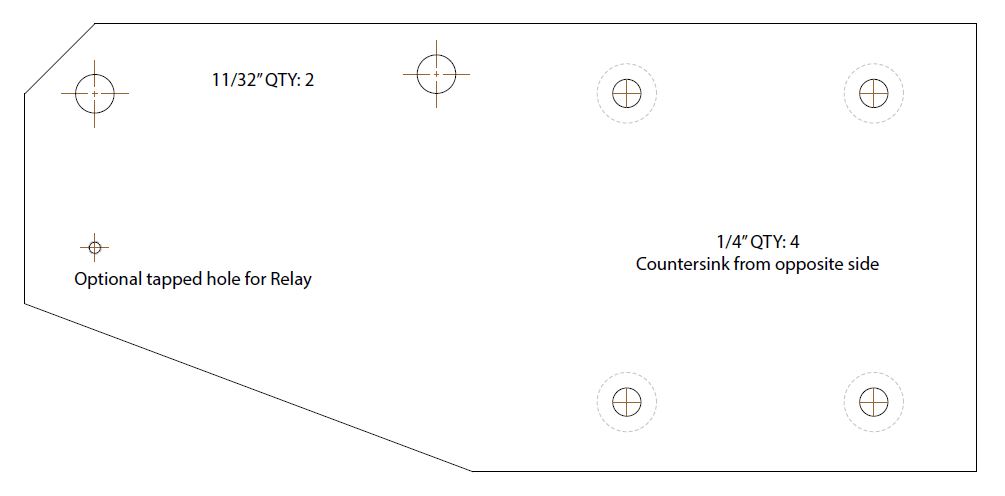
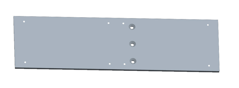
I made this out of some scrap .250" aluminum 6061-T6 I had laying around. If you want to make your own, pick up a plate from ebay or wherever for less than $15. The maximum dimensions are 0.25" X 4.0" X 8.5" and here is a link to a pdf file that you can print out as a template; just make sure it prints to scale!
Mounting Bracket Template
For the install, here is the bracket and the hardware. I ended up only using one of the threaded holes for mounting the relay since the other one was covered up too much by the compressor.
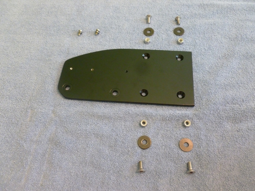
Here is the back side showing the countersink holes and the (optional) slight 0.010"x0.625" counterbores on the holes that mount to the body. The weld nuts have little raised protrusions that dig in to the aluminum when tightened. I chose to give them a little relief but you don't have to. For the countersinks, I am using metric flatheads so I used a 90° sink. You could also use 1/4-20 screws with an 82° sink if you want.
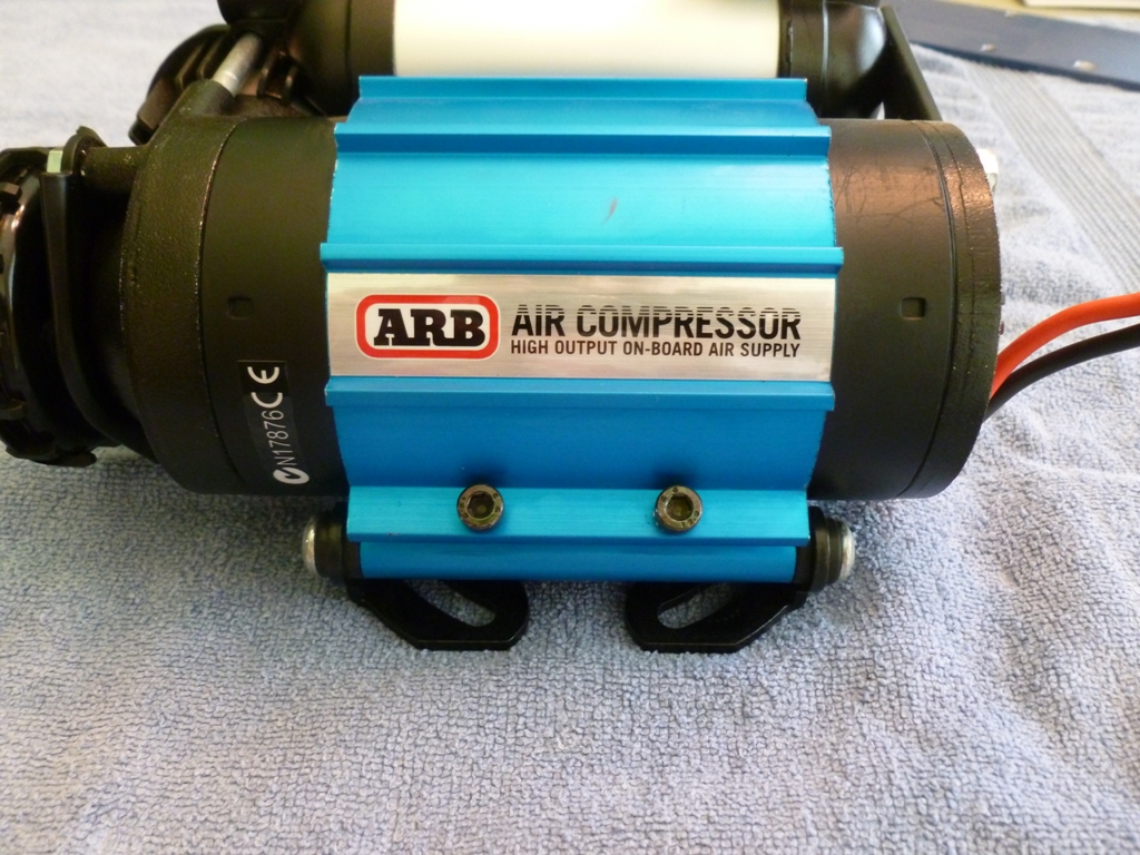
There is quite a bit of rearrangement of the compressor parts to get it into the right orientation. The main thing is to reverse the blue heat sink mount. Start by loosening these black socket head cap screws to be able to loosen the blue heat sink mount.
Then undo the two bolts shown here, rotate the black reservoir bracket out of the way, slide off the blue heat sink mount, reverse it, slide it back on, install bolts.
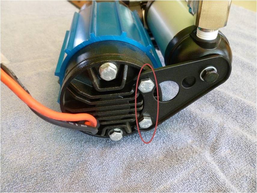
It should look approximately like this:
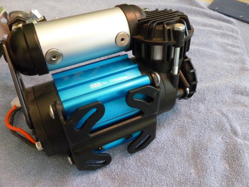
Then take the black base bracket off by removing the four shoulder screws that screw into the blue mount.
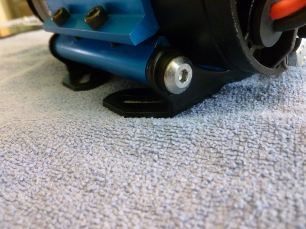
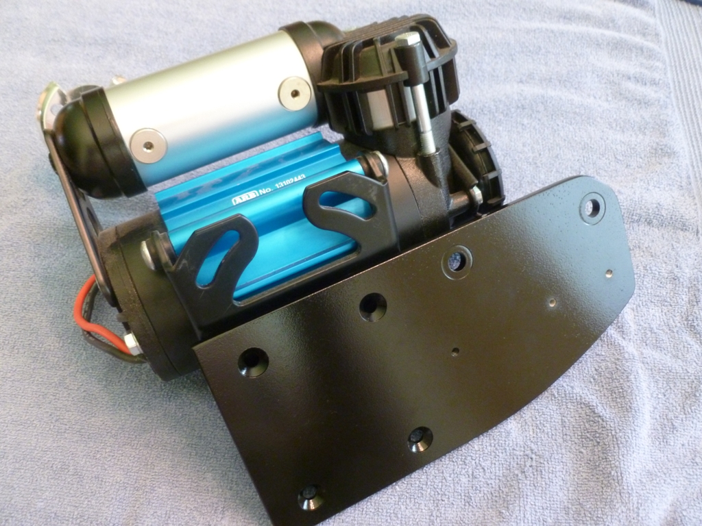
Attach the ARB base bracket to the aluminum mounting bracket using your hardware.
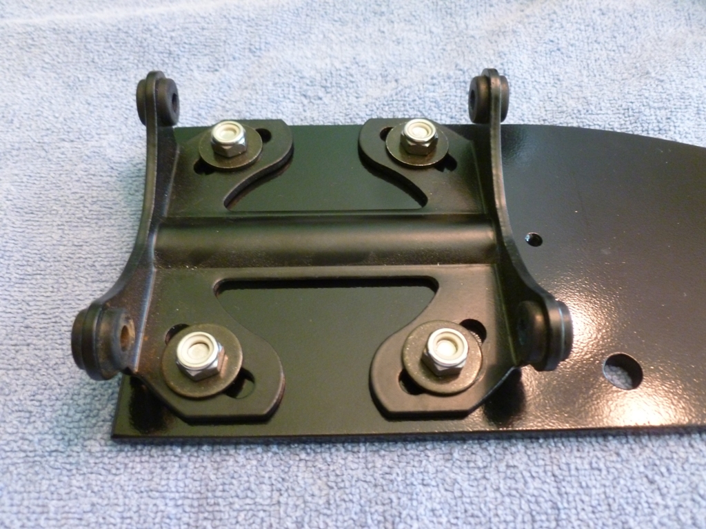
Re-attach the black base bracket to the blue heat sink mount using the four shoulder screws. Re-tighten the blue heat sink mount once you're happy with the position it will take in the engine bay. Note that the custom bracket does not sit perpendicularly to the ground.
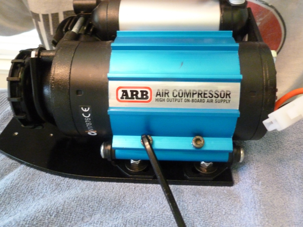
Before you actually install the bracket to the body, mount your relay.
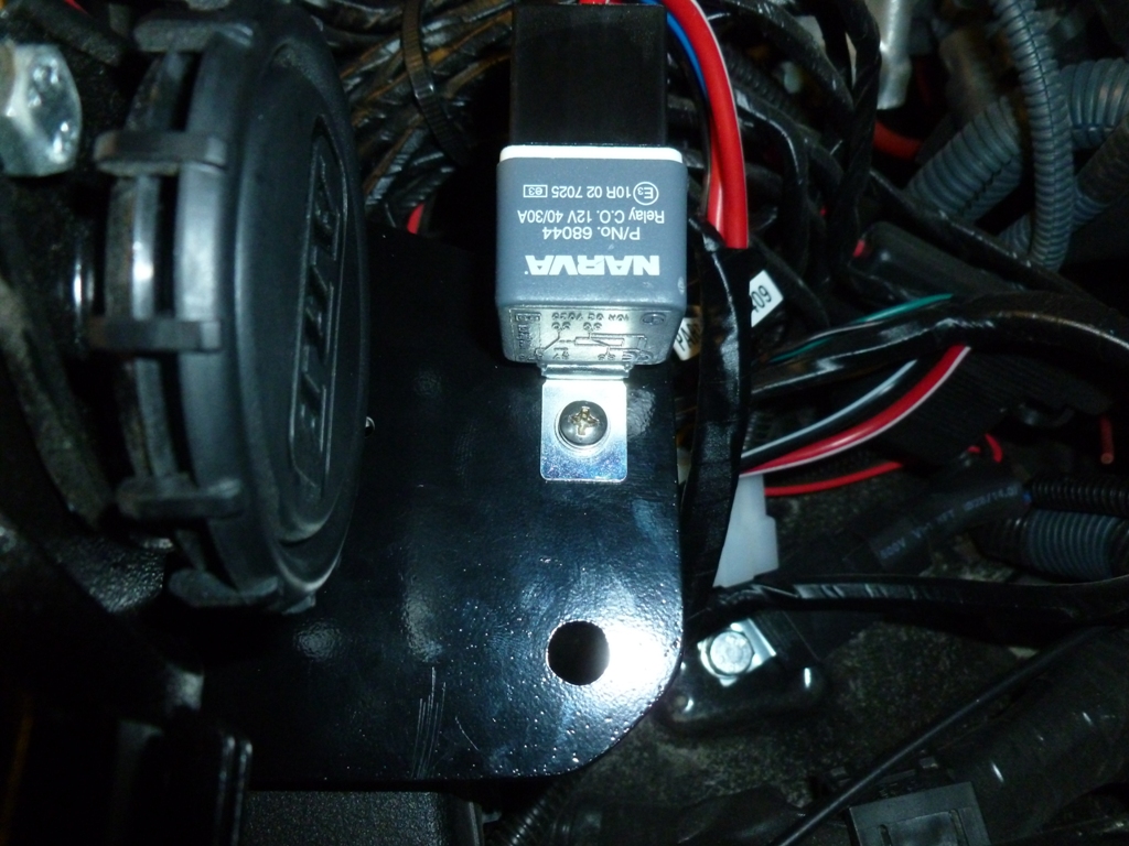
Now thread your M8 bolts in and tighten with a box end wrench.
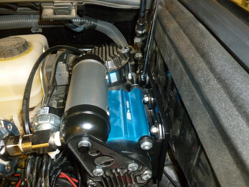
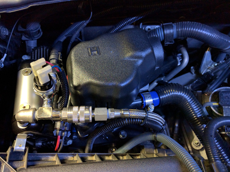
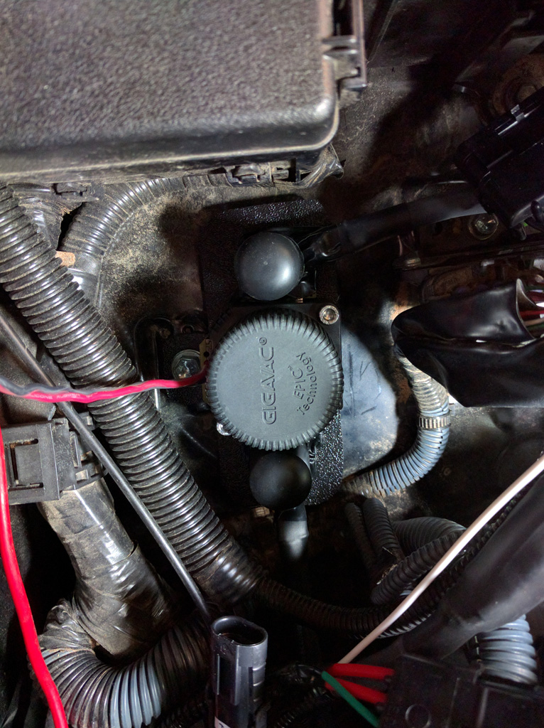
As you can see, I positioned the air chuck from the ARB inflation accessory kit to point parallel to the ground. I did this because it saves me from having to mount the compressor lower and also should minimize the amount of debris that falls into the chuck opening. Almost all ARB installation pictures show it pointing straight up but in my area of work, you never want an exposed connection pointing up.
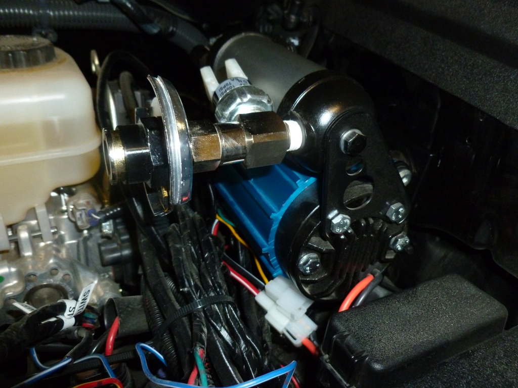
One more picture showing the filter and the relay out of harm's way.
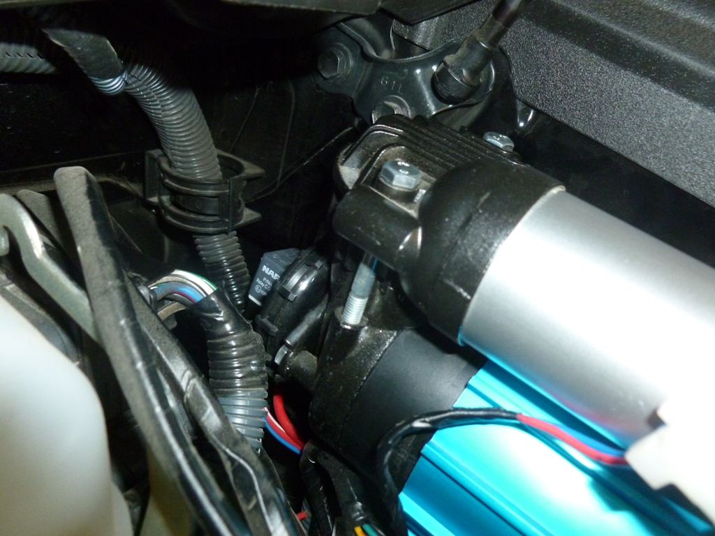
If you plan to install the locker solenoids, you may want to consider how they will be oriented and rotate the reservoir appropriately. There may not be enough room to go straight up without hitting the hood. You could rotate the pressure switch to the other side, or face the solenoids toward the body and the connections facing up or down. Hopefully you get the idea and can figure something out.
I hope this write up helps someone.
Could you please explain, what is the pressure switch for? can I just put hose connector directly to compressor without using T connector that distributes air to pressure switch and hose connector.
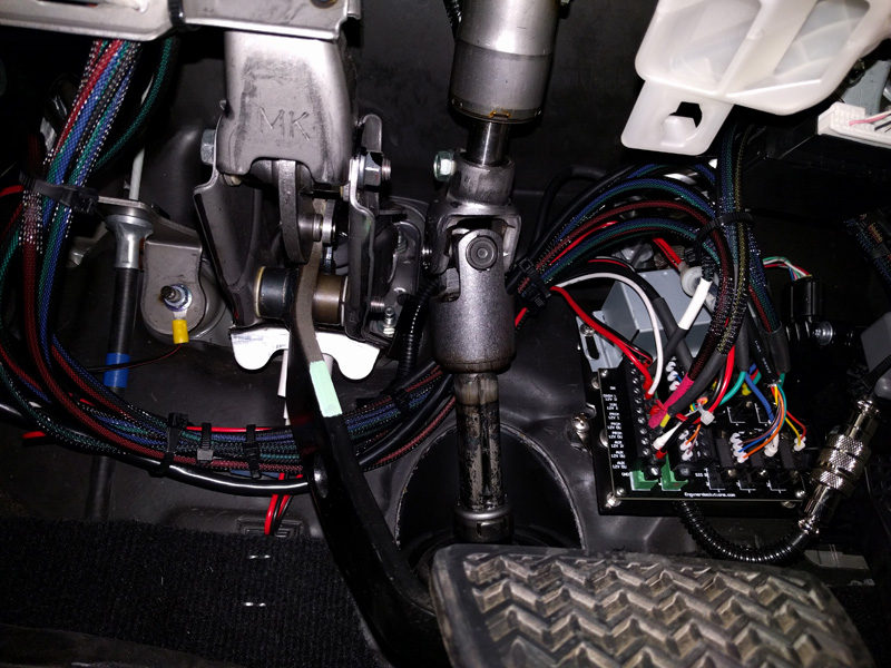
Where did you also place compressor on/off switch ? Could you please post a picture of your control panel?
Also where did you connect red yellow wire (supposed to be connected to ignition) and blue white (dash illumination).
I've made plate, installed compressor and stuck at wiring step and where to put on/off switch.

Last edited:

 where its going to be.










 opcorn:


