gfxcruncher's build/adventures

gfxcruncher

Member
Here we go, because the world needs another build thread… Just about everything I've done has started here looking at someone's build thread or write up, so a big thanks to everyone posting on here!

Most recent poser pic
<a data-flickr-embed="true" href="https://www.flickr.com/photos/186714437@N07/50197179927/in/dateposted-public/" title="Untitled"><img src="https://live.staticflickr.com/65535/50197179927_0662e286c6_c.jpg" width="800" height="533" alt="Untitled"></a><script async src="//embedr.flickr.com/assets/client-code.js" charset="utf-8"></script>

It all started when a buddy of mine was having problems with a 3rd gen he bought, while doing internet research the google brought me to T4R... Two years later in August 2017 I finally pulled the trigger and got a 4th gen. I originally wanted a 3rd but couldn’t find any in great shape. Started looking at and driving a bunch of 4ths before finding one that had a really good frame, interior was nice and drove like it only had 60k on it. Really wanted a silver or gray 4th, but stumbled on a 2007 SR5 Nautical Blue with about 152k on the clock that checked the boxes. Initially wasn’t crazy about the blue, but man, has that grown on me, I love this color.

I didn’t take any pictures of it before putting the lift and tires on, this is about the earliest pic I have.

<a data-flickr-embed="true" href="https://www.flickr.com/photos/186714437@N07/49466260808/in/album-72157712917270126/" title="Runner 1"><img src="https://live.staticflickr.com/65535/49466260808_4742f4e627_b.jpg" width="1024" height="476" alt="Runner 1"></a><script async src="//embedr.flickr.com/assets/client-code.js" charset="utf-8"></script>

I’m not a photographer, and usually forget to stop and take pics, you've been warned...
 
Last edited:
Register to hide this ad
Think I had this thing maybe a month before I started tearing into it.

First up was lift and tires: Toytec “ultimate” kit with 255/75/R17 Goodyear Duratracs and Spidertrax. Because wheel spacers are what the cool kids do!

<a data-flickr-embed="true" href="https://www.flickr.com/photos/186714437@N07/49470207331/in/album-72157712917270126/" title="IMG_1799"><img src="https://live.staticflickr.com/65535/49470207331_75334c57db_b.jpg" width="1024" height="768" alt="IMG_1799"></a><script async src="//embedr.flickr.com/assets/client-code.js" charset="utf-8"></script>

No pics needed really, it’s been documented tons here, but I do remember it entailed trimming the front bumper cover, sawzalling a seized LCA bolt off. Couldn’t press the bushings out and didn’t think the neighbors would be liking me too much if I torched the bushings out, so I put new LCAs on.

Shortly after, I swapped out the dash lights to LEDs, cause 1/2 of them were out anyway. Went with blue backlighting and white indicators, matches the truck nicely.

Wouldn’t have attempted it without these threads:

yosh2000's ultimate LED swap info thread - Toyota 4Runner Forum - Largest 4Runner Forum

and

DIY: Interior LED swap (cluster, HVAC, switches, window, *steering wheel)
 
Last edited:
Storage / Sleeping Platform Prototype

Signed up for a winter trip and decided I needed some sort of sleeping platform, saw several on here that were awesome and decided to roll one of my own. I never took pictures of it, but basically, it was a box that sat slightly taller than the wheel wells, when the 60 portion of the front seat was folded down there was an extension that would screw on and create a sleeping platform. It was never fully completed and only served as a prototype to start using. You can kinda see some of it here:

<a data-flickr-embed="true" href="https://www.flickr.com/photos/186714437@N07/49466827131/in/album-72157712917056918/" title="IMG_2536"><img src="https://live.staticflickr.com/65535/49466827131_3046c680ef_b.jpg" width="768" height="1024" alt="IMG_2536"></a><script async src="//embedr.flickr.com/assets/client-code.js" charset="utf-8"></script>

I used that for quite a while and over that time started making mental notes about what I would want in a real setup.

Here’s the thread for the winter trip I went on, it was my first time wheeling and it totally hooked me, there’s pics at the end of the thread if you’re interested… this trip got me back into getting outside.

Canaan loop + optional camp and 2nd day at Flagpole - VA/WV/MD/DC/Southern PA members
 
Roof Rack

So I made a roof rack from that superstrut stuff you get at the local big box store, it was gonna be awesome! it worked ok…

<a data-flickr-embed="true" href="https://www.flickr.com/photos/186714437@N07/49470046033/in/album-72157712920336451/" title="IMG_1947"><img src="https://live.staticflickr.com/65535/49470046033_83d93d55b6_b.jpg" width="1024" height="768" alt="IMG_1947"></a><script async src="//embedr.flickr.com/assets/client-code.js" charset="utf-8"></script>

Then a buddy who shall remain unnamed got a Prinsu rack and the side rails were damaged, CBI sent him new side rails and said to bend the old ones in half.


You know where this is going :naughty:

A little work with the harbor freight press, an order to Tnutz for rails, a fairing from CBI and 300 bucks later I had me a Prinsu!

winner winner chicken dinner :thumb:
 
Liftgate Lights

One thing I noticed over time is that I’m usually at the back of the truck doing stuff, like dinner, making coffee etc… and there’s no light! I’m always forgetting to put that headband light thing on and I’m all about convenience, so I added some lights to the lift gate.

Used 4 of these from Oznium (the 3W stainless steel version)
LED Bolt Flush Mount Lights | Bright + 12 Volt | Oznium LEDs

<a data-flickr-embed="true" href="https://www.flickr.com/photos/186714437@N07/49466333328/in/dateposted-public/" title="IMG_2070"><img src="https://live.staticflickr.com/65535/49466333328_e37c9748ff_b.jpg" width="768" height="1024" alt="IMG_2070"></a><script async src="//embedr.flickr.com/assets/client-code.js" charset="utf-8"></script>

<a data-flickr-embed="true" href="https://www.flickr.com/photos/186714437@N07/49466333288/in/dateposted-public/" title="IMG_2071"><img src="https://live.staticflickr.com/65535/49466333288_6320ed467e_b.jpg" width="768" height="1024" alt="IMG_2071"></a><script async src="//embedr.flickr.com/assets/client-code.js" charset="utf-8"></script>
 
Bussmann RTMR

A little out of order… but before adding any electrical accessories I wanted to come up with how the wiring was to be done or it was gonna turn into a rats nest real quick. Looked at the Bluesea stuff but really liked how clean the Bussmann setup is, incorporating the fuses and relays in one enclosure, so clean. I liked the idea even more after finding this 6 part tutorial at bodenzord.com.
DIY Bussmann RTMR Fuse Block, Part 1 – Introduction | Bodenzord He even sourced and linked the parts needed!
I did make a few minor changes, but basically straight up copied that setup.

Also, did a DIY power tray out of aluminum.

Top
<a data-flickr-embed="true" href="https://www.flickr.com/photos/186714437@N07/49466828386/in/album-72157712917247922/" title="IMG_1981"><img src="https://live.staticflickr.com/65535/49466828386_e8f5136966_b.jpg" width="1024" height="1024" alt="IMG_1981"></a><script async src="//embedr.flickr.com/assets/client-code.js" charset="utf-8"></script>

Bottom with everything wired up
<a data-flickr-embed="true" href="https://www.flickr.com/photos/186714437@N07/49466333703/in/album-72157712917247922/" title="IMG_1985"><img src="https://live.staticflickr.com/65535/49466333703_93080d39a5_b.jpg" width="768" height="1024" alt="IMG_1985"></a><script async src="//embedr.flickr.com/assets/client-code.js" charset="utf-8"></script>

Installed
<a data-flickr-embed="true" href="https://www.flickr.com/photos/186714437@N07/49466333553/in/album-72157712917247922/" title="IMG_1998"><img src="https://live.staticflickr.com/65535/49466333553_0110fd4255_b.jpg" width="768" height="1024" alt="IMG_1998"></a><script async src="//embedr.flickr.com/assets/client-code.js" charset="utf-8"></script>

Had to come up with a place to mount the switches and the sunglasses holder wasn’t seeing any use
<a data-flickr-embed="true" href="https://www.flickr.com/photos/186714437@N07/49466828221/in/album-72157712917247922/" title="IMG_1989"><img src="https://live.staticflickr.com/65535/49466828221_8839b02998_b.jpg" width="768" height="1024" alt="IMG_1989"></a><script async src="//embedr.flickr.com/assets/client-code.js" charset="utf-8"></script>

I had leftover aluminum from the tray, so I bent it up, painted it black and mounted it with some screws through the sides.

pic from the windshield side, you can't see the gap when it's installed in the headliner.
<a data-flickr-embed="true" href="https://www.flickr.com/photos/186714437@N07/49467051732/in/album-72157712917247922/" title="IMG_2008"><img src="https://live.staticflickr.com/65535/49467051732_7bcdfde31f_b.jpg" width="768" height="1024" alt="IMG_2008"></a><script async src="//embedr.flickr.com/assets/client-code.js" charset="utf-8"></script>

Can’t claim credit for this idea, saw it here:
Overhead 6 switch panel - Toyota 4Runner Forum - Largest 4Runner Forum
 
One thing I noticed over time is that I’m usually at the back of the truck doing stuff, like dinner, making coffee etc… and there’s no light! I’m always forgetting to put that headband light thing on and I’m all about convenience, so I added some lights to the lift gate.

Used 4 of these from Oznium (the 3W stainless steel version)
LED Bolt Flush Mount Lights | Bright + 12 Volt | Oznium LEDs

<a data-flickr-embed="true" href="https://www.flickr.com/photos/186714437@N07/49466333328/in/dateposted-public/" title="IMG_2070"><img src="https://live.staticflickr.com/65535/49466333328_e37c9748ff_b.jpg" width="768" height="1024" alt="IMG_2070"></a><script async src="//embedr.flickr.com/assets/client-code.js" charset="utf-8"></script>

<a data-flickr-embed="true" href="https://www.flickr.com/photos/186714437@N07/49466333288/in/dateposted-public/" title="IMG_2071"><img src="https://live.staticflickr.com/65535/49466333288_6320ed467e_b.jpg" width="768" height="1024" alt="IMG_2071"></a><script async src="//embedr.flickr.com/assets/client-code.js" charset="utf-8"></script>

Nice, how painful was the install on this? Guessing you pulled the lift gate interior panel and routed wiring through the loom at the top of the hatch and tied into the rear dome? Looks great, might be the single mod I need to do the most - the lighting back there is abysmal.
 
Nice, how painful was the install on this? Guessing you pulled the lift gate interior panel and routed wiring through the loom at the top of the hatch and tied into the rear dome? Looks great, might be the single mod I need to do the most - the lighting back there is abysmal.


Hey 11
I wired them to a switch in the back that goes to the Bussmann, but wiring them to the dome is a great idea too. I would imagine you wouldn’t overload the circuit, I don’t think they draw that much power, especially if you changed out the interior lights to leds too.
I think getting the wires fished up through the gate and secured so the window doesn’t catch them was the worst part. But it was worth it, they make a huge difference back there.


Sent from my iPhone using Tapatalk
 
Are you running baja designs lights in your fog pockets?? Been thinking about doing that to mine?

Argh! Looks like my earlier response got wiped out with the forum glitch today...

Yeah, I was running the squadron sports in that location. I made some cheesy aluminum brackets instead of the taco ones from BD. The lights were great there, my brackets, meh, but they got the job done. I say "was" because I hit a deer in November and am currently working on another solution since right now the cover is basically zip tied onto the truck...
 
Storage System / Sleeping Platform

Reposting since this got wiped out too, thank goodness I had prewritten and saved it locally. Here we go...

After using the prototype storage system for a while, and looking at a bunch of them on here, I had a pretty good idea of what I wanted in a system.
  • Use the 60 split of the rear seat for the sleeping platform
  • Incorporate a fridge slide
  • make it easy to remove
  • Maximize drawer space
  • Be able to fire up food and coffee with minimal setup
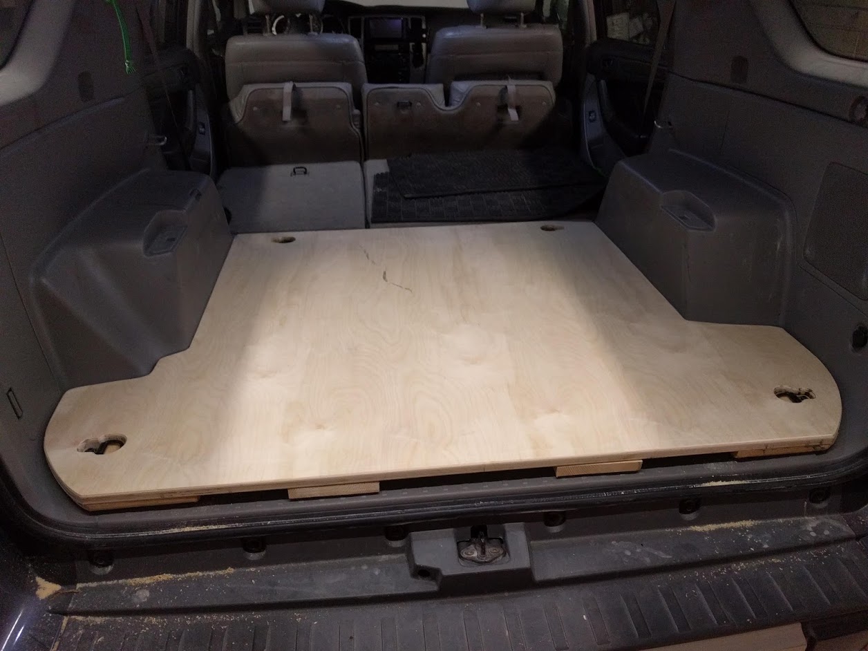
Started by making a deck plate to build everything off of, it mounts by using the factory cargo tie down points (I may add a few more attachment points at a later date). The idea came from how Goose Gear does their system.
After scribing the cargo area profile, transferred it to some 3/4 baltic birch ply, test fit to make sure it was good to go.

<a data-flickr-embed="true" href="https://www.flickr.com/photos/186714437@N07/49466331488/in/album-72157712918658248/" title="IMG_2737"><img src="https://live.staticflickr.com/65535/49466331488_8639158915_b.jpg" width="1024" height="768" alt="IMG_2737"></a><script async src="//embedr.flickr.com/assets/client-code.js" charset="utf-8"></script>

Removed the deck plate and started laying out the frame. For the frame I went with a mix of 3/4 tubing and some 3/16 x 1 1/4 flat stock. The 3/16 flat stock is for the vertical supports, it’s plenty strong and keeps the width to a minimum, giving some extra space for drawer width. Once everything was all set up I attached the frame to the deck plate with tee nuts so it could be removed if the need ever arrises.

<a data-flickr-embed="true" href="https://www.flickr.com/photos/186714437@N07/49466331533/in/album-72157712918658248/" title="IMG_2736"><img src="https://live.staticflickr.com/65535/49466331533_25eec6199d_b.jpg" width="768" height="1024" alt="IMG_2736"></a><script async src="//embedr.flickr.com/assets/client-code.js" charset="utf-8"></script>

<a data-flickr-embed="true" href="https://www.flickr.com/photos/186714437@N07/49466825701/in/album-72157712918658248/" title="IMG_2741"><img src="https://live.staticflickr.com/65535/49466825701_7e2571615b_b.jpg" width="1024" height="768" alt="IMG_2741"></a><script async src="//embedr.flickr.com/assets/client-code.js" charset="utf-8"></script>

Welding 3/16 thick tabs flush to the bottom of the 3/4 tube worked out perfectly to support the 1/2 ply insets.

<a data-flickr-embed="true" href="https://www.flickr.com/photos/186714437@N07/49466824561/in/album-72157712918658248/" title="IMG_2896"><img src="https://live.staticflickr.com/65535/49466824561_3924023126_b.jpg" width="1024" height="768" alt="IMG_2896"></a><script async src="//embedr.flickr.com/assets/client-code.js" charset="utf-8"></script>

The fridge slide isn’t anything too special, the tray tilts down and has some stops to keep it from hitting the bumper cover. It mounts to the 3/4 tube with 1/4”-20 rivet nuts so I can remove it when not on a trip.

<a data-flickr-embed="true" href="https://www.flickr.com/photos/186714437@N07/49467048287/in/album-72157712918658248/" title="IMG_2892"><img src="https://live.staticflickr.com/65535/49467048287_b1f2a891e1_b.jpg" width="768" height="1024" alt="IMG_2892"></a><script async src="//embedr.flickr.com/assets/client-code.js" charset="utf-8"></script>

<a data-flickr-embed="true" href="https://www.flickr.com/photos/186714437@N07/49467047872/in/album-72157712918658248/" title="IMG_2940"><img src="https://live.staticflickr.com/65535/49467047872_2d39255f1d_b.jpg" width="768" height="1024" alt="IMG_2940"></a><script async src="//embedr.flickr.com/assets/client-code.js" charset="utf-8"></script>

The dead space behind the wheel well on the right side has a ARB single compressor and power inverter. This might be my favorite part of the project, it’s nice not having to dig around for the portable compressor and popping the hood to air up. The left side has a power distribution bar.

<a data-flickr-embed="true" href="https://www.flickr.com/photos/186714437@N07/49466824816/in/album-72157712918658248/" title="IMG_2887"><img src="https://live.staticflickr.com/65535/49466824816_4b469f1d5b_b.jpg" width="1024" height="768" alt="IMG_2887"></a><script async src="//embedr.flickr.com/assets/client-code.js" charset="utf-8"></script>

<a data-flickr-embed="true" href="https://www.flickr.com/photos/186714437@N07/49466824931/in/album-72157712918658248/" title="IMG_2877"><img src="https://live.staticflickr.com/65535/49466824931_c57184d8db_b.jpg" width="768" height="1024" alt="IMG_2877"></a><script async src="//embedr.flickr.com/assets/client-code.js" charset="utf-8"></script>

Installing the seat platform is pretty quick. Remove the lower seat cushion (two 14mm bolts) and bolt the platform in place. There’s two tee nuts on the deck plate and two rivet nut inserts on the 3/4 tube.

<a data-flickr-embed="true" href="https://www.flickr.com/photos/186714437@N07/50190108056/in/album-72157712918658248/" title="Untitled"><img src="https://live.staticflickr.com/65535/50190108056_890f38b99e_z.jpg" width="640" height="529" alt="Untitled"></a><script async src="//embedr.flickr.com/assets/client-code.js" charset="utf-8"></script>

<a data-flickr-embed="true" href="https://www.flickr.com/photos/186714437@N07/50189562963/in/album-72157712918658248/" title="Untitled"><img src="https://live.staticflickr.com/65535/50189562963_a6fa689bd5_c.jpg" width="800" height="600" alt="Untitled"></a><script async src="//embedr.flickr.com/assets/client-code.js" charset="utf-8"></script>

At various points there are footman loops welded to the frame and I made some straps using flat hooks. I wished that I could use some of that track stuff, but the 1/2 ply isn’t thick enough, this works good though.

<a data-flickr-embed="true" href="https://www.flickr.com/photos/186714437@N07/49467048352/in/album-72157712918658248/" title="IMG_2891"><img src="https://live.staticflickr.com/65535/49467048352_3554958f0e_b.jpg" width="768" height="1024" alt="IMG_2891"></a><script async src="//embedr.flickr.com/assets/client-code.js" charset="utf-8"></script>

The left drawer is where I stuff most of my tools and spares, the right drawer has my stove and cooking stuff.

<a data-flickr-embed="true" href="https://www.flickr.com/photos/186714437@N07/49468393163/in/album-72157712918658248/" title="IMG_2962"><img src="https://live.staticflickr.com/65535/49468393163_789c8d0730_b.jpg" width="1024" height="768" alt="IMG_2962"></a><script async src="//embedr.flickr.com/assets/client-code.js" charset="utf-8"></script>

<a data-flickr-embed="true" href="https://www.flickr.com/photos/186714437@N07/49468882106/in/album-72157712918658248/" title="IMG_2961"><img src="https://live.staticflickr.com/65535/49468882106_01eb4bd269_b.jpg" width="1024" height="768" alt="IMG_2961"></a><script async src="//embedr.flickr.com/assets/client-code.js" charset="utf-8"></script>

For finishing, the ply is painted with some gray porch floor paint and the frame is sprayed with some black satin enamel spray paint.

<a data-flickr-embed="true" href="https://www.flickr.com/photos/186714437@N07/49468882171/in/album-72157712918658248/" title="IMG_2960"><img src="https://live.staticflickr.com/65535/49468882171_917118be80_b.jpg" width="1024" height="768" alt="IMG_2960"></a><script async src="//embedr.flickr.com/assets/client-code.js" charset="utf-8"></script>

There's a few more progress shots in this Flickr album, I wasn't planning on doing a build thread, so they're kinda random and not in any sort of order...
cargo build | Flickr

 
Last edited:
Random Trip Pics

Photography is not really one of my hobbies, and I usually forget (or don’t feel like) stopping to get nice shots when I’m out on trips, but the truck sees it’s fair share of dirt…

Definitely taken on one of my first trips, this mud hole is completely by-passable, cleaning all that out sucks! Unless I know my weekend is going to be unavoidably full of mud, I take the bypass.
<a data-flickr-embed="true" href="https://www.flickr.com/photos/186714437@N07/49466827706/in/album-72157712917056918/" title="IMG_2202"><img src="https://live.staticflickr.com/65535/49466827706_d1037ca5d9_b.jpg" width="768" height="1024" alt="IMG_2202"></a><script async src="//embedr.flickr.com/assets/client-code.js" charset="utf-8"></script>

A wet Memorial Day weekend, the Roadhouse Tarp came in real handy.
<a data-flickr-embed="true" href="https://www.flickr.com/photos/186714437@N07/49466333028/in/album-72157712917056918/" title="IMG_2274"><img src="https://live.staticflickr.com/65535/49466333028_8f58d17003_b.jpg" width="1024" height="768" alt="IMG_2274"></a><script async src="//embedr.flickr.com/assets/client-code.js" charset="utf-8"></script>

Finding tunnels on forest service roads, it's like finding a ten dollar bill on the sidewalk.
<a data-flickr-embed="true" href="https://www.flickr.com/photos/186714437@N07/49469109257/in/album-72157712917056918/" title="IMG_3242"><img src="https://live.staticflickr.com/65535/49469109257_a3f441bee2_b.jpg" width="1024" height="768" alt="IMG_3242"></a><script async src="//embedr.flickr.com/assets/client-code.js" charset="utf-8"></script>

Pinstripes, check!
<a data-flickr-embed="true" href="https://www.flickr.com/photos/186714437@N07/49469106612/in/album-72157712917056918/" title="IMG_3126"><img src="https://live.staticflickr.com/65535/49469106612_a35b26f3e4_b.jpg" width="768" height="1024" alt="IMG_3126"></a><script async src="//embedr.flickr.com/assets/client-code.js" charset="utf-8"></script>

I love getting to see stuff like this
<a data-flickr-embed="true" href="https://www.flickr.com/photos/186714437@N07/49469028291/in/album-72157712917056918/" title="IMG_3156"><img src="https://live.staticflickr.com/65535/49469028291_83a4fcec95_b.jpg" width="768" height="1024" alt="IMG_3156"></a><script async src="//embedr.flickr.com/assets/client-code.js" charset="utf-8"></script>
 
Hidden Winch Mount

After going back and forth between a C4 Low Pro and the Bud Built hidden winch setup, I decided I like the lines of the factory bumper cover and don’t really need additional clearance. Saw this thread Factory Bumper Winch Install and decided to roll my own.

Used this this winch plate from Amazon and some 3/16 x 2” angle iron

Made the brackets flush with the top of the crash bar, they tie into the crash bar mounting points as well as the rad support.

<a data-flickr-embed="true" href="https://www.flickr.com/photos/186714437@N07/49467050357/in/album-72157712960874443/" title="IMG_2627"><img src="https://live.staticflickr.com/65535/49467050357_803d3e8196_b.jpg" width="768" height="1024" alt="IMG_2627"></a><script async src="//embedr.flickr.com/assets/client-code.js" charset="utf-8"></script>

<a data-flickr-embed="true" href="https://www.flickr.com/photos/186714437@N07/49467050372/in/album-72157712960874443/" title="IMG_2626"><img src="https://live.staticflickr.com/65535/49467050372_c57359de24_b.jpg" width="768" height="1024" alt="IMG_2626"></a><script async src="//embedr.flickr.com/assets/client-code.js" charset="utf-8"></script>

added some diagonal bracing

<a data-flickr-embed="true" href="https://www.flickr.com/photos/186714437@N07/49467050237/in/album-72157712960874443/" title="IMG_2635"><img src="https://live.staticflickr.com/65535/49467050237_b76c6b528e_b.jpg" width="768" height="1024" alt="IMG_2635"></a><script async src="//embedr.flickr.com/assets/client-code.js" charset="utf-8"></script>

After getting into the project I saw an opportunity to put recovery points higher than the towing tie downs or the other bolt on ones out there. They’re in line with the frame rail and IMO fit with the bumper design and look good.
This is the point in this project I got a little off the rails, couldn’t find anything off the shelf and was getting quotes for 400 to basically get 1x2 bar stock with a 1” hole drilled in it. Ordered some bar stock from the local yard for 20 bucks and got a 1” drill bit off amazon for around 40 bucks, then proceeded with a LOT of patience on my little bench top drill press and finished off the exterior of the radius with a cut off wheel and flap disk.

<a data-flickr-embed="true" href="https://www.flickr.com/photos/186714437@N07/49466331888/in/album-72157712960874443/" title="IMG_2672"><img src="https://live.staticflickr.com/65535/49466331888_8d385dea37_b.jpg" width="768" height="1024" alt="IMG_2672"></a><script async src="//embedr.flickr.com/assets/client-code.js" charset="utf-8"></script>

<a data-flickr-embed="true" href="https://www.flickr.com/photos/186714437@N07/49467049992/in/album-72157712960874443/" title="IMG_2680"><img src="https://live.staticflickr.com/65535/49467049992_94ac2c4944_b.jpg" width="768" height="1024" alt="IMG_2680"></a><script async src="//embedr.flickr.com/assets/client-code.js" charset="utf-8"></script>

<a data-flickr-embed="true" href="https://www.flickr.com/photos/186714437@N07/49466331978/in/album-72157712960874443/" title="IMG_2683"><img src="https://live.staticflickr.com/65535/49466331978_02a4ac96f1_b.jpg" width="768" height="1024" alt="IMG_2683"></a><script async src="//embedr.flickr.com/assets/client-code.js" charset="utf-8"></script>

Finished it off by making a bracket to mount the license plate to that would cover the fairlead when I’m not out, removes with two bolts.

<a data-flickr-embed="true" href="https://www.flickr.com/photos/186714437@N07/49467049922/in/album-72157712960874443/" title="IMG_2691"><img src="https://live.staticflickr.com/65535/49467049922_0d0b418b9a_b.jpg" width="768" height="1024" alt="IMG_2691"></a><script async src="//embedr.flickr.com/assets/client-code.js" charset="utf-8"></script>
 
Last edited:
<a data-flickr-embed="true" href="https://www.flickr.com/photos/186714437@N07/49466331488/in/album-72157712918658248/" title="IMG_2737"><img src="https://live.staticflickr.com/65535/49466331488_8639158915_b.jpg" width="1024" height="768" alt="IMG_2737"></a><script async src="//embedr.flickr.com/assets/client-code.js" charset="utf-8"></script>


Didn't realize you had a plywood base under there...working on something a bit similar, though my drawers are going to be all wood since I don't have those metal fab skills (I really just need to pull the trigger on a welder and address that...) I've gotta say, your setup is definitely one of the cleanest, well thought-out cargo build outs I've seen.

Going to have a pull out table underneath the platform...

IMG_20200118_120752.jpg


Hey, now that you're going with a full metal bumper, what are you going to do with the old winch mount there?
 
Didn't realize you had a plywood base under there...working on something a bit similar, though my drawers are going to be all wood since I don't have those metal fab skills (I really just need to pull the trigger on a welder and address that...) I've gotta say, your setup is definitely one of the cleanest, well thought-out cargo build outs I've seen.

Going to have a pull out table underneath the platform...

Hey, now that you're going with a full metal bumper, what are you going to do with the old winch mount there?

Hey man! I haven't been out since I met you over the holidays... I'm way overdue for a trip!

I like the idea of having a pull out table... sleeping at the wheel well height gives me just enough headroom to move around pretty comfortably and didn't want to sacrifice the drawer height.

Yeah, since you're doing your own wrenching and are handy, you should get a welder, really opens up the possibilities of what you can put together. I've been using this Vucan Welder from Harbor Freight. Works better using 220 and honestly, I've only been using the presets instead of manually dialing it in.

Sorry, already promised the winch mount to another buddy...
 
Hey man! I haven't been out since I met you over the holidays... I'm way overdue for a trip!

I like the idea of having a pull out table... sleeping at the wheel well height gives me just enough headroom to move around pretty comfortably and didn't want to sacrifice the drawer height.

Yeah, since you're doing your own wrenching and are handy, you should get a welder, really opens up the possibilities of what you can put together. I've been using this Vucan Welder from Harbor Freight. Works better using 220 and honestly, I've only been using the presets instead of manually dialing it in.

Sorry, already promised the winch mount to another buddy...

That's one of the ones I've been eyeing up - but of course one project leads to another and I'll have to run a 220 line into the garage. Not a huge deal, just something else to do!

No worries about the winch mount, just another good excuse for me to roll me own...though, Liv is pushing for a full bumper, sooo....

Did make some good progress on the drawer setup today, got the carcass built along with the drawers - slides got delivered, so next is getting them mounted up and painting everything.

We've just done some fire roads and stuff since, but itching to get back out, might be starting a new job in a week or 2, so might try to get a few day trip in down to WV/VA before then....
 
That's one of the ones I've been eyeing up - but of course one project leads to another and I'll have to run a 220 line into the garage. Not a huge deal, just something else to do!


No worries about the winch mount, just another good excuse for me to roll me own...though, Liv is pushing for a full bumper, sooo....


Did make some good progress on the drawer setup today, got the carcass built along with the drawers - slides got delivered, so next is getting them mounted up and painting everything.


We've just done some fire roads and stuff since, but itching to get back out, might be starting a new job in a week or 2, so might try to get a few day trip in down to WV/VA before then....


Good deal. Looking forward to seeing what you did with your setup next time we meet up, that chuck box you got is sweet.
And good luck with the new job [emoji106]


Sent from my iPhone using Tapatalk
 
DIY Rear Swingouts

A few people have asked for a writeup on this... I’ve said I’m not a photographer and I’m seeing now that I’m not much of a writer either, lol.

Project Background: I looked around at rear bumpers and hitch mount carriers and wasn’t all that crazy about any of the options available but was tired of not running with a spare around town and having to hoist it up on the roof rack for trips. I actually like the lines of the factory cover and looking under the bumper cover, figured I could make my own swing outs.

I didn’t plan on doing a writeup on this, but I think I got enough pics to explain it pretty good should anyone decide to do the same.
(insert do at your own risk disclaimer blah, blah, blah…)

Finished project:
<a data-flickr-embed="true" href="https://www.flickr.com/photos/186714437@N07/49494426003/in/album-72157712917249546/" title="IMG_3441"><img src="https://live.staticflickr.com/65535/49494426003_c3e6f6091b_b.jpg" width="1024" height="889" alt="IMG_3441"></a><script async src="//embedr.flickr.com/assets/client-code.js" charset="utf-8"></script>

<a data-flickr-embed="true" href="https://www.flickr.com/photos/186714437@N07/49495141342/in/album-72157712917249546/" title="IMG_3439"><img src="https://live.staticflickr.com/65535/49495141342_7c9ae0f116_b.jpg" width="1024" height="783" alt="IMG_3439"></a><script async src="//embedr.flickr.com/assets/client-code.js" charset="utf-8"></script>

Incomplete list of things needed

Started off getting some angle iron to bolt to the frame rail, I was after 3 x 4 x 1/4 but the yard had 3 1/2 x 5 x 5/16. To order what I wanted would have been a lot more expensive than using what they had lying around. Although I didn’t need 5/16 thick stock, having the additional height worked out for the better. (sometimes it’s good not to have a plan) It’s cut so that the factory tow loop mounting holes could be used, doesn’t interfere with the rear body mount and sits just proud of the rear crossmember. On my truck the factory nuts in the frame wound up breaking off so I drilled them out and used M10 weld nuts, I also added a third one. You can see the holes for the factory tie down points on the right piece in the pic.

<a data-flickr-embed="true" href="https://www.flickr.com/photos/186714437@N07/49468881246/in/album-72157712917249546/" title="IMG_3203"><img src="https://live.staticflickr.com/65535/49468881246_ff784b3bcc_b.jpg" width="768" height="1024" alt="IMG_3203"></a><script async src="//embedr.flickr.com/assets/client-code.js" charset="utf-8"></script>

The cutout that was made to clear the body mount got reused to make a tab securing the top of the bracket to the crossmember. Nice hands lol.
<a data-flickr-embed="true" href="https://www.flickr.com/photos/186714437@N07/49468881046/in/album-72157712917249546/" title="IMG_3205"><img src="https://live.staticflickr.com/65535/49468881046_b79336331e_b.jpg" width="768" height="1024" alt="IMG_3205"></a><script async src="//embedr.flickr.com/assets/client-code.js" charset="utf-8"></script>

The notched out section on the bottom is so the bracket doesn’t interfere with the crossmember. I also added a diagonal brace tying the tab to the angle.
<a data-flickr-embed="true" href="https://www.flickr.com/photos/186714437@N07/49469109442/in/album-72157712917249546/" title="IMG_3213"><img src="https://live.staticflickr.com/65535/49469109442_43c68d97ef_b.jpg" width="768" height="1024" alt="IMG_3213"></a><script async src="//embedr.flickr.com/assets/client-code.js" charset="utf-8"></script>

The next few steps were preformed with the truck frame leveled and on blocks so I could ensure the parts being welded to the brackets were square to each other.

Tacked a 3 x 3 x 1/4 piece of square tube flush with the top of the angle, this worked out great because it lines up the bottom of the next piece (that the hinge mounts to) to right about where the foot step is on the bumper. This piece is about 8 3/4” inches long, and the bottom is rounded slightly, it gets really close to the bottom of the bumper cover at that point. (pic doesn't show the 3 x 3 rounded off)
<a data-flickr-embed="true" href="https://www.flickr.com/photos/186714437@N07/49468880401/in/album-72157712917249546/" title="IMG_3266"><img src="https://live.staticflickr.com/65535/49468880401_539f07d745_b.jpg" width="1024" height="768" alt="IMG_3266"></a><script async src="//embedr.flickr.com/assets/client-code.js" charset="utf-8"></script>

The piece on top of the 3 x 3 that the hinge is welded to is 4 x 6 x 1/4. with a 1/4” thick end cap. My local steel yard had 4 x 4 x 1/4 and ordering 4 x 6 would have been a lot (this is a recurring theme throughout this project). Made 4 x 6 out of 4 x 4 and saved some cash.
<a data-flickr-embed="true" href="https://www.flickr.com/photos/186714437@N07/49469000271/in/album-72157712917249546/" title="59166179055__12E33884-6048-4EFB-BAA0-EA38EB43AAC3"><img src="https://live.staticflickr.com/65535/49469000271_c556a2dca8_b.jpg" width="768" height="1024" alt="59166179055__12E33884-6048-4EFB-BAA0-EA38EB43AAC3"></a><script async src="//embedr.flickr.com/assets/client-code.js" charset="utf-8"></script>
 
DIY Rear Swingouts (Continued)

The big struggle I had was locating these pieces with the cover off so I could weld them up. I’m sure someone has a better way to do it, I wound up taking the bumper cover on and off a lot.

Important: truck is leveled on blocks/jack stands at this point.

With the bumper cover on, set up a laser level to establish the vertical line of the bracket coming through the cover and mark it on the brake light (I made marks on painters tape in the pic), repeat on the other side. Remove the bumper cover and line the 4x6 piece up with the laser, do both sides at the same time and ensure they are square to each other. (I cut a 2 x 4 to length making sure my end cuts were square) Then tacked them together.
<a data-flickr-embed="true" href="https://www.flickr.com/photos/186714437@N07/49468880236/in/album-72157712917249546/" title="IMG_3277"><img src="https://live.staticflickr.com/65535/49468880236_5c57c56d84_b.jpg" width="1024" height="768" alt="IMG_3277"></a><script async src="//embedr.flickr.com/assets/client-code.js" charset="utf-8"></script>

Figuring out how far the faces of the 4 x 6 should protrude from the cover, that was a pain. With the cover on I did my best to take a measurement from a point I could reference when the cover is off, like at the corner of the tail light, or at a body line in the lift gate.
In hindsight, it might have been easer to locate the strike plate for the latches (later step) and work backwards off that measurement, but at that point I only had a vague idea of how the latches we’re going to work.

Since I was doing double swing arms, I was pretty worried about the arms not lining up, so I used a long level spanning the hinges to ensure the hinges were lined up. After endless hammer tapping to get everything just right, I tacked everything up.
<a data-flickr-embed="true" href="https://www.flickr.com/photos/186714437@N07/49469108682/in/album-72157712917249546/" title="IMG_3279"><img src="https://live.staticflickr.com/65535/49469108682_e5342240e7_b.jpg" width="768" height="1024" alt="IMG_3279"></a><script async src="//embedr.flickr.com/assets/client-code.js" charset="utf-8"></script>

I did make one modification to the hinges, drilled two 1/2” holes on the backs for a couple of plug welds.
<a data-flickr-embed="true" href="https://www.flickr.com/photos/186714437@N07/49469108472/in/album-72157712917249546/" title="IMG_3287"><img src="https://live.staticflickr.com/65535/49469108472_a0e9ba3163_b.jpg" width="768" height="1024" alt="IMG_3287"></a><script async src="//embedr.flickr.com/assets/client-code.js" charset="utf-8"></script>

At this point I removed the brackets, finished the welds and added more supports. Yeah, I could have cut gussets out and they would have worked fine, I was being lazy. Are those welds ugly? Why yes, yes they are…
<a data-flickr-embed="true" href="https://www.flickr.com/photos/186714437@N07/49468390888/in/album-72157712917249546/" title="IMG_3291"><img src="https://live.staticflickr.com/65535/49468390888_5e3d429be6_b.jpg" width="768" height="1024" alt="IMG_3291"></a><script async src="//embedr.flickr.com/assets/client-code.js" charset="utf-8"></script>

Reinstalled the brackets, installed the sleeve in the hinge and took a measurement for the arms, there's a 1/4" gap between the arms where they meet, cut and notched the arms, mocked it all up with the arm catch and latch.
<a data-flickr-embed="true" href="https://www.flickr.com/photos/186714437@N07/49468879881/in/album-72157712917249546/" title="IMG_3283"><img src="https://live.staticflickr.com/65535/49468879881_687dc3ce69_b.jpg" width="1024" height="768" alt="IMG_3283"></a><script async src="//embedr.flickr.com/assets/client-code.js" charset="utf-8"></script>

I found it easier at this point to take the arm off and to the bench to weld them on, it was just easier to keep everything square.

After cutting the arms to length I made the arm catch on the ladder arm with angle, it’s spaced away from the arm by 1/8" on the top and bottom so I could put some hard polyurethane strips in there to keep it from squeaking and provide some vibration dampening. Tapped holes for 1/4-20 threads and installed the latch on the tire arm. The latch catch is a leftover cutoff from the 1 1/2 x 3 tube, I made the latch catch the same height as the one that comes with the latch.
<a data-flickr-embed="true" href="https://www.flickr.com/photos/186714437@N07/49495102136/in/dateposted-public/" title="IMG_3299"><img src="https://live.staticflickr.com/65535/49495102136_981237433d_b.jpg" width="768" height="1024" alt="IMG_3299"></a><script async src="//embedr.flickr.com/assets/client-code.js" charset="utf-8"></script>

The strike plate is some leftover angle from the brackets mounted to the crossmember with weld nuts. I lucked out here, there was just enough room to slide some 1/4 plate between the strike plate and the backside of the arm. Surprisingly even though it’s metal to metal contact there’s no squeaking or movement, probably due to the 4xinnovations hinges having no play and the latch drawing the arm pretty tight, I was originally going to use some rubber spacers or something in there. If I were to do it over again, I would mount the strike plate and use that as a reference point to locate the 4x6 pieces of the bracket front to back. (sorry if this doesn’t make sense)
<a data-flickr-embed="true" href="https://www.flickr.com/photos/186714437@N07/49468878951/in/album-72157712917249546/" title="IMG_3398"><img src="https://live.staticflickr.com/65535/49468878951_d2fbb97413_b.jpg" width="768" height="1024" alt="IMG_3398"></a><script async src="//embedr.flickr.com/assets/client-code.js" charset="utf-8"></script>
The catch for the ladder arm latch is another 1 1/2 x 3 cutoff welded to the strike plate and the latch mounts to the 1/4 plate that hangs down.

Probably easier to see it working in a video. (this is a video)
<a data-flickr-embed="true" href="https://www.flickr.com/photos/186714437@N07/49469028176/in/album-72157712917249546/" title="IMG_3397"><img src="https://live.staticflickr.com/31337/49469028176_1a767452dd_b.jpg" width="576" height="1024" alt="IMG_3397"></a><script async src="//embedr.flickr.com/assets/client-code.js" charset="utf-8"></script>
 
DIY Rear Swingouts (Continued)

At some point after the arms and latches were on I was testing it by swinging the arms out and pushing down on them to see if they would flex, they did. The bracket was flexing away from the truck frame at the top... I added an extension to the top of the bracket, covering more of the rail and added another weld nut, still had flexing and it was flexing the side rail. (after looking closely, it looks like the side rails are made of thinner material than the crossmember) Since I wasn't using the foam insert on top of the crossmember there was just enough room to add a tab on each bracket and then tie them together with some threaded rod, that fixed the flex problem.

(Didn't get a pic. next time I have the cover off, I'll update here with one)

The tire support is some of the 1 1/2 x 3 tube the angled supports are 1 1/2 x 1 1/2 x 3/16 tube. I made the mounting plate out of 1/4” I had lying around and pressed a few old wheel studs in 1/2” holes (I could have made the holes slightly larger, it was a tight fit) wound up using a washer on the studs to space the wheel out slightly, the lug nuts were bottoming out. The mounting plate is tilted 5deg.
<a data-flickr-embed="true" href="https://www.flickr.com/photos/186714437@N07/49469107447/in/album-72157712917249546/" title="IMG_3411"><img src="https://live.staticflickr.com/65535/49469107447_9db65ed337_b.jpg" width="768" height="1024" alt="IMG_3411"></a><script async src="//embedr.flickr.com/assets/client-code.js" charset="utf-8"></script>

The ladder is 1 1/2 x 1 1/2 x 3/16 square tube and has a 10 deg slant to match the rear body line. On the sides of the ladder I put some M8 weld nuts so that I could attach a bracket to hold a jerry can and hi-lift, this is my daily, so I made it removable to keep a cleaner look around town. Man, that's a clean truck...
<a data-flickr-embed="true" href="https://www.flickr.com/photos/186714437@N07/49495502902/in/dateposted-public/" title="IMG_3586"><img src="https://live.staticflickr.com/65535/49495502902_c091ae334a_b.jpg" width="768" height="1024" alt="IMG_3586"></a><script async src="//embedr.flickr.com/assets/client-code.js" charset="utf-8"></script>

Used some angle for the bottom rung and mounted the license plate to that with side view LED bolts from Oznium. The lights aren’t the brightest, I don’t really care, they’re just there so I don’t get pulled over.
<a data-flickr-embed="true" href="https://www.flickr.com/photos/186714437@N07/49494785058/in/dateposted-public/" title="IMG_3587"><img src="https://live.staticflickr.com/65535/49494785058_e2dabeb421_b.jpg" width="1024" height="768" alt="IMG_3587"></a><script async src="//embedr.flickr.com/assets/client-code.js" charset="utf-8"></script>

Used another 1 1/2 x 3 cutoff to make a backup camera relocation mount, some rod spaced off by 1/8” and welded on provides for zip ties to keep the wires neat.
<a data-flickr-embed="true" href="https://www.flickr.com/photos/186714437@N07/49495280046/in/dateposted-public/" title="IMG_3589"><img src="https://live.staticflickr.com/65535/49495280046_bbe026fdc0_b.jpg" width="1024" height="768" alt="IMG_3589"></a><script async src="//embedr.flickr.com/assets/client-code.js" charset="utf-8"></script>

<a data-flickr-embed="true" href="https://www.flickr.com/photos/186714437@N07/49494785033/in/dateposted-public/" title="IMG_3588"><img src="https://live.staticflickr.com/65535/49494785033_9aff120a94_b.jpg" width="1024" height="768" alt="IMG_3588"></a><script async src="//embedr.flickr.com/assets/client-code.js" charset="utf-8"></script>

Once the ladder was on I could then weld the hinge catches on, I wanted to make sure the lift gate would clear the ladder.

I finished it with etch primer and Rustoleum hammered finish black matte paint which looks more like a gunmetal to me. Yeah, bad idea, that stuff doesn’t hold up very good at all, but at this point I was ready to be done with the project. Maybe I’ll wire wheel it all off and finish it properly if I ever get bored. ha.

And the real reason anyone does swing outs… overlander level 100 unlocked!
<a data-flickr-embed="true" href="https://www.flickr.com/photos/186714437@N07/49468389538/in/album-72157712917249546/" title="IMG_3487"><img src="https://live.staticflickr.com/65535/49468389538_c3f5d9e552_b.jpg" width="768" height="1024" alt="IMG_3487"></a><script async src="//embedr.flickr.com/assets/client-code.js" charset="utf-8"></script>

That’s about it, feel free to ask questions if there’s anything that’s not clear.
 

Members online

Forum statistics

Threads
278,310
Messages
3,554,078
Members
248,016
Latest member
Advally Service

Trending content

Back
Top