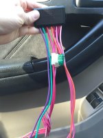
I typed this up as a reply to a PM but realized I'm others would benefit. I'll ad to this later and update it so hopefully it can be searched and used time and time again. I'll be happy to help anyone with a remote start. I'm new here and want to do my part. So I'll just leave this right here and answer any questions others might have. If this is something you think would be helpfully, post here and let me know as well.
You can buy an avital 4103, directed 556uw and a spare key for about $70 all from amazon and have remote start and I'll help.
This applies to all DEI products such as viper, avital, etc
Primary Harness
H1/1 RED/WHITE (-) 200mA AUX TRUNK RELEASE OUTPUT
I didn't hook this up as I didn't find any documentation but I will look into it because I would like the option to go up and down from the remote. I have all the other windows controller so I its likely doable
H1/2 RED (+) CONSTANT POWER INPUT
I always connect this behind the fuses on the relay pack, tie this wire together with the ribbon cable and zip tie to wire tape it to the harness, as this will make it easier later.
H1/3 BROWN (+) SIREN OUTPUT
This connects to the red wire of the siren or can be used to trigger the horn for arm/disarm confirmation. You don't have to connect this to make it work and you don't have to use any of the alarm functions if you don't want to.
H1/5 BLACK (-) CHASSIS GROUND INPUT --- Chassis ground
yep
H1/6 VIOLET (+) DOOR TRIGGER INPUT
not used
H1/7 BLUE (-) INSTANT TRIGGER INPUT
green/yellow - Back Door ECU in rear liftgate, white 25 pin plug, pin 7, you'll have to run the wire back there and through the existing wire loom
H1/8 GREEN (-) DOOR TRIGGER INPUT, ZONE 3
used for door triggers LF red/black, RF red/yel, LR pink/black, RR pink/blue;These all need to be diode isolated, You will need 4 small diodes with the silver banded side of the all the diodes connected together to the brain and the 4 legs left connected to each door trigger. These wires are located at the body ECU on RR of dash fuse box, middle white 24 pin plug, you will have to take the 2 10mm bolts out that hold the fuse box in
H1/9 BLACK/WHITE (-) 200mA DOMELIGHT SUPERVISION OUTPUT --- Pin 8, plug to right of fuse box - White (-)
dash fuse box, white 20 pin plug (A), pin 8
H1/10 WHITE/BLUE (-) REMOTE START ACTIVATION INPUT
this would be some type of external intput to trigger a remote start sequence, rarely used
H1/11 WHITE (+)/(-) SELECTABLE LIGHT FLASH OUTPUT --- 16 Plug, left of fuses - Green (+) - Needs Relay
I think I found this on the bottom left corner of the dash fuse box in a wire harness, you just have to test it with a multimeter to know for sure, best to check them all
H1/12 ORANGE (-) 500mA GROUND WHEN ARMED OUTPUT
you won't need this wire unless you do window modules like I did, otherwise its not commonly used
Auxilary Harness
you shouldn't need any of these wires as the vehicle locks and unlocks with the factory arm and disarm wires
Door lock harness, 3-pin connector
1 LIGHT BLUE (-) UNLOCK (+) LOCK OUTPUT --- Driver's kick, 18 pin plug - Blue (Type B?)
2 EMPTY NOT USED --- None
3 GREEN (-) LOCK (+) UNLOCK OUTPUT --- Driver's kick, 18 pin plug - Green (Type B?)
This looks accurate, I know I connected the blue wire to the green wire and the green wire to the blue wire, it will take two button presses to unlock all doors as it does with the factory remote, can be changed but I need to be 100% sure of what you have to help with that
Ribbon cable
This is from the relay pack and plugs into the brain
Heavy gauge relay satellite wiring diagram
H/1 PURPLE STARTER OUTPUT TO STARTER (STARTER SIDE) --- Ignition switch harness - Green/Black (+) - Starter side
H/2 GREEN STARTER INPUT FROM IGNITION (KEY SIDE) --- Ignition switch harness - Green/Black (+) - Key side
H/3 RED (+) (30A) HIGH CURRENT 12V INPUT --- Can be spliced with H/6 and H/8?
connect this to red or white blue
H/4 ORANGE OUTPUT TO ACCESSORY CIRCUIT --- Ignition switch harness - White/Green (+) - A/C
H/5 PINK OUTPUT TO PRIMARY IGNITION CIRCUIT --- Ignition switch harness - Black/Red (+)
H/6 RED (+) (30A) HIGH CURRENT 12V INPUT --- Can be spliced with H/3 and H/8?
H/7 PINK/WHITE OUTPUT TO SECOND IGNITION CIRCUIT --- Ignition switch harness - Blue/Yellow (+)
H/8 RED/WHITE (+) (30A) HIGH CURRENT 12V INPUT --- Can be spliced with H/3 and H/6?
connect this to red or white/bluej
the white/blue is a higher current wire, I don't remember if the red or red/white connects to the starter relay but whatever one does, connect that to white blue and the other to red, you also don't have to cut the starter wire and do the start kill, you can ignore the green wire and just tap the purple into the starter wire
Relay satellite 4-pin connector Is this needed?
1 BLUE (-) 200mA STATUS OUTPUT ---
you will use this to trigger a bypass module for the anti theft system, I used a dei 556u, This is a key in a box module and there are many varieties that all work basically the same, will discuss more later
Remote start harness, (H3) 5-pin connector
H3/1 BLACK/WHITE (-) NEUTRAL SAFETY SWITCH INPUT --- None
connect this to ground
H3/2 VIOLET/WHITE TACHOMETER INPUT WIRE --- Engine control module, connector E8, Pin 5 - Black/White (AC)
this is located above the gas pedel, kinda hard to get to, I used a scotch lock which I don't like to use but makes it much easier to tap when hard to reach, you don't necessarily have to use this since the 4runner doesn't require you to hold the key till it starts, I did anyways, you will have to learn the tach or program the remote start to tachless mode
H3/3 BROWN (+) BRAKE SHUTDOWN INPUT WIRE --- Switch above brake pedal - Green/Yellow (+)
got this wire next to the parking light wire I believe
H3/4 GRAY (-) HOOD PINSWITCH INPUT, ZONE 6 --- None (Install one maybe?)
not needed
H3/5 BLUE/WHITE (-) 200 mA 2ND STATUS/REAR DEFOGGER - Latched Pulsed ---
I didn't try this yet so I'm not sure, it says its a green red wire, it might need a relay, it should be 12v when defrost off and drop to nothing when turned on
Aux4
not needed
for a bypass I used the dei module but there are others, they generally take power, ignition ground and negative trigger when remote starting (blue wire mentioned earlier), put a programmed key in the box and wrap the copper coil around the ignion switch, voila, keys are cheap and instructions are available to program them, I bought one but haven't tried it, but it sounds like you don't even need to turn the key to program in which case you don't need to get it cut. Buy it, program it and stick it in the box. I have my valet key in mine currently but thats my plan
Thats it, its a lot but I've put 100's of these things on, its doable for the average person, but you need to spend some time bench wiring this. I'll post pictures of what this looks like later. Does this site have a picture upload?
You can buy an avital 4103, directed 556uw and a spare key for about $70 all from amazon and have remote start and I'll help.
This applies to all DEI products such as viper, avital, etc
Primary Harness
H1/1 RED/WHITE (-) 200mA AUX TRUNK RELEASE OUTPUT
I didn't hook this up as I didn't find any documentation but I will look into it because I would like the option to go up and down from the remote. I have all the other windows controller so I its likely doable
H1/2 RED (+) CONSTANT POWER INPUT
I always connect this behind the fuses on the relay pack, tie this wire together with the ribbon cable and zip tie to wire tape it to the harness, as this will make it easier later.
H1/3 BROWN (+) SIREN OUTPUT
This connects to the red wire of the siren or can be used to trigger the horn for arm/disarm confirmation. You don't have to connect this to make it work and you don't have to use any of the alarm functions if you don't want to.
H1/5 BLACK (-) CHASSIS GROUND INPUT --- Chassis ground
yep
H1/6 VIOLET (+) DOOR TRIGGER INPUT
not used
H1/7 BLUE (-) INSTANT TRIGGER INPUT
green/yellow - Back Door ECU in rear liftgate, white 25 pin plug, pin 7, you'll have to run the wire back there and through the existing wire loom
H1/8 GREEN (-) DOOR TRIGGER INPUT, ZONE 3
used for door triggers LF red/black, RF red/yel, LR pink/black, RR pink/blue;These all need to be diode isolated, You will need 4 small diodes with the silver banded side of the all the diodes connected together to the brain and the 4 legs left connected to each door trigger. These wires are located at the body ECU on RR of dash fuse box, middle white 24 pin plug, you will have to take the 2 10mm bolts out that hold the fuse box in
H1/9 BLACK/WHITE (-) 200mA DOMELIGHT SUPERVISION OUTPUT --- Pin 8, plug to right of fuse box - White (-)
dash fuse box, white 20 pin plug (A), pin 8
H1/10 WHITE/BLUE (-) REMOTE START ACTIVATION INPUT
this would be some type of external intput to trigger a remote start sequence, rarely used
H1/11 WHITE (+)/(-) SELECTABLE LIGHT FLASH OUTPUT --- 16 Plug, left of fuses - Green (+) - Needs Relay
I think I found this on the bottom left corner of the dash fuse box in a wire harness, you just have to test it with a multimeter to know for sure, best to check them all
H1/12 ORANGE (-) 500mA GROUND WHEN ARMED OUTPUT
you won't need this wire unless you do window modules like I did, otherwise its not commonly used
Auxilary Harness
you shouldn't need any of these wires as the vehicle locks and unlocks with the factory arm and disarm wires
Door lock harness, 3-pin connector
1 LIGHT BLUE (-) UNLOCK (+) LOCK OUTPUT --- Driver's kick, 18 pin plug - Blue (Type B?)
2 EMPTY NOT USED --- None
3 GREEN (-) LOCK (+) UNLOCK OUTPUT --- Driver's kick, 18 pin plug - Green (Type B?)
This looks accurate, I know I connected the blue wire to the green wire and the green wire to the blue wire, it will take two button presses to unlock all doors as it does with the factory remote, can be changed but I need to be 100% sure of what you have to help with that
Ribbon cable
This is from the relay pack and plugs into the brain
Heavy gauge relay satellite wiring diagram
H/1 PURPLE STARTER OUTPUT TO STARTER (STARTER SIDE) --- Ignition switch harness - Green/Black (+) - Starter side
H/2 GREEN STARTER INPUT FROM IGNITION (KEY SIDE) --- Ignition switch harness - Green/Black (+) - Key side
H/3 RED (+) (30A) HIGH CURRENT 12V INPUT --- Can be spliced with H/6 and H/8?
connect this to red or white blue
H/4 ORANGE OUTPUT TO ACCESSORY CIRCUIT --- Ignition switch harness - White/Green (+) - A/C
H/5 PINK OUTPUT TO PRIMARY IGNITION CIRCUIT --- Ignition switch harness - Black/Red (+)
H/6 RED (+) (30A) HIGH CURRENT 12V INPUT --- Can be spliced with H/3 and H/8?
H/7 PINK/WHITE OUTPUT TO SECOND IGNITION CIRCUIT --- Ignition switch harness - Blue/Yellow (+)
H/8 RED/WHITE (+) (30A) HIGH CURRENT 12V INPUT --- Can be spliced with H/3 and H/6?
connect this to red or white/bluej
the white/blue is a higher current wire, I don't remember if the red or red/white connects to the starter relay but whatever one does, connect that to white blue and the other to red, you also don't have to cut the starter wire and do the start kill, you can ignore the green wire and just tap the purple into the starter wire
Relay satellite 4-pin connector Is this needed?
1 BLUE (-) 200mA STATUS OUTPUT ---
you will use this to trigger a bypass module for the anti theft system, I used a dei 556u, This is a key in a box module and there are many varieties that all work basically the same, will discuss more later
Remote start harness, (H3) 5-pin connector
H3/1 BLACK/WHITE (-) NEUTRAL SAFETY SWITCH INPUT --- None
connect this to ground
H3/2 VIOLET/WHITE TACHOMETER INPUT WIRE --- Engine control module, connector E8, Pin 5 - Black/White (AC)
this is located above the gas pedel, kinda hard to get to, I used a scotch lock which I don't like to use but makes it much easier to tap when hard to reach, you don't necessarily have to use this since the 4runner doesn't require you to hold the key till it starts, I did anyways, you will have to learn the tach or program the remote start to tachless mode
H3/3 BROWN (+) BRAKE SHUTDOWN INPUT WIRE --- Switch above brake pedal - Green/Yellow (+)
got this wire next to the parking light wire I believe
H3/4 GRAY (-) HOOD PINSWITCH INPUT, ZONE 6 --- None (Install one maybe?)
not needed
H3/5 BLUE/WHITE (-) 200 mA 2ND STATUS/REAR DEFOGGER - Latched Pulsed ---
I didn't try this yet so I'm not sure, it says its a green red wire, it might need a relay, it should be 12v when defrost off and drop to nothing when turned on
Aux4
not needed
for a bypass I used the dei module but there are others, they generally take power, ignition ground and negative trigger when remote starting (blue wire mentioned earlier), put a programmed key in the box and wrap the copper coil around the ignion switch, voila, keys are cheap and instructions are available to program them, I bought one but haven't tried it, but it sounds like you don't even need to turn the key to program in which case you don't need to get it cut. Buy it, program it and stick it in the box. I have my valet key in mine currently but thats my plan
Thats it, its a lot but I've put 100's of these things on, its doable for the average person, but you need to spend some time bench wiring this. I'll post pictures of what this looks like later. Does this site have a picture upload?
Last edited: