How-to: Wiring a '99+ Bezel Into a '97 - A Comprehensive Tutorial

4Runner4Leon

Senior Member
What follows is my attempt at the most comprehensive set of wiring instructions for swapping a ‘99+ center dash bezel into a ’97-98. The wiring aspects of this swap include rewiring the ECT switch, the hazard switch, the back window switch, the defogger switch, the backlight illumination, and the newly added power outlets. I just completed this swap, swapping an ’02 bezel into my ’97 Limited.

I’ve read numerous threads about the swap, but with the loss of many Photobucket links in other posts, a lot of the needed info was difficult to recreate. So I’ll try to lay out all the wiring details of this conversion, complete with wiring diagrams, photos, and tips and tricks. That way you won’t just see me say “do this”, you’ll see the supporting data behind having to “do this”. The goal is for this to become a one-stop shop for anyone contemplating this conversion, without the need to research numerous posts with missing links, or confusing information or instructions. I won’t detail the mechanical aspects of this swap, such as what parts to remove, how to get to the switches, etc, because that part is fairly straightforward. We’ll just focus on the wiring.

To give credit where credit is due, here are some sources I looked at that helped me get started:

http://www.toyota-4runner.org/2695579-post275.html
http://www.toyota-4runner.org/3rd-gen-t4rs/230792-tyler-james-incs-oem-97-limited.html
http://www.toyota-4runner.org/3rd-g...nner-digital-clock-revived-tooth-surgery.html
https://www.yotatech.com/forums/f2/those-who-want-put-99-center-dash-bezel-43660/index2.html
http://www.toyota-4runner.org/3rd-gen-t4rs/114346-how-99-center-dash-conversion-wiring.html
http://www.toyota-4runner.org/3rd-gen-t4rs/234735-dash-center-bezel-questions.html
https://www.youtube.com/watch?v=N2JopkvWd0s&feature=youtu.be

Before we start, here are the wiring color codes that I will use, same as Toyota’s and most other wiring conventions.

B - Black
W - White
R - Red
G - Green
L - Blue
O - Orange
LG - Light Green

If there is a tracer (i.e. a wire with one main color with a tracer of another color), I’ll use the letter for the main color first, and the letter for the tracer color second, i.e. R-B means red wire with a black tracer.

So without a further ado, let’s get started.

What parts to get from the ‘99+ donor.

- Dash bezel, including the combination switch which includes the ECT, defogger, and back window switches
- Y-shaped duct behind bezel
- Hazard switch, its connector, and harness (the connector and harness are not a must, but helpful as I’ll discuss below)
- C23 white connector attaching to the back of the donor combination switch, along with as much of the harness as you can get
- Power outlets at the bottom of the bezel and connectors and wiring harnesses attached to them

Below are some photos of what I got from the donor.

Bezel and Y-duct:


You can’t see the Y-duct because it’s behind the bezel, but you definitely want to get it, because the ’97 duct will not line up with the ‘99+ vents.

Combination Switch:


Combination Switch Harnesses:


In the harness photo, the C23 connector is on the lower left, and the hazard connector is smack in the middle. The orange connector is not needed, nor is the clock connector in lower center, since you’ll be reusing your old clock and connector (the clocks are identical).

Power Outlets and Harnesses:


I peeled the wood off the ’99 bezel and painted it. I first tried silver, but didn’t like how it looked in my truck, so I hit it again with some satin trim black paint:


Preparing the donor harnesses.

First I separated the harnesses from each other:


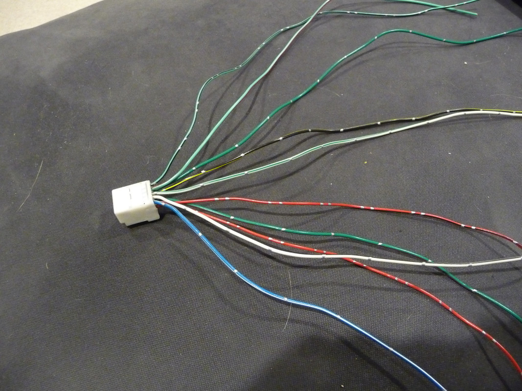
Then removed the jacket from the C23 harness to expose the wires:


Before we leave the topic of donor parts, let’s talk about the C23 connector a little more (you’ll be getting very cozy with the C23 connector, might as well get to know it well). Below is a schematic of the C23 connector, and how its 10 terminals fit into the ’99 wiring system:


It has 2 terminals for illumination, 3 terminals for the back window, 2 terminals for the rear defogger switch, 2 terminals for rear defogger indicator bulb, and one terminal for ECT; 10 terminals total. We’ll keep referring back to this when figuring out how to wire all the switches.


Preparing your ‘97 for the swap.

As I said earlier, I won’t discuss how to remove the bezel and get to the wires; that’s covered fairly well in other threads, and is really straightforward. Just pull up and remove the console rear trim piece, pull up and remove the shifter trim piece, pull off and remove the AC/heater face panel and remove the two screws behind it, and then pull off the bezel. You’ll have some bulbs and connectors to disconnect along the way, so take good notes.

Then reroute the ECT and back window harnesses from the console area up behind the bezel and to the center opening near the AC vents and clock. To do that, you’ll need to open up the harness with those wires, because they are tied together with other wires that need to stay in place (for parking brake indicator and 4WD switch). Looking below, it’s the harness along the left side of the console – you’ll need to cut the zip ties and remove some of the taping holding all the wires together:


Now separate the ECT, back window, and security wires from the other wires that will be staying:
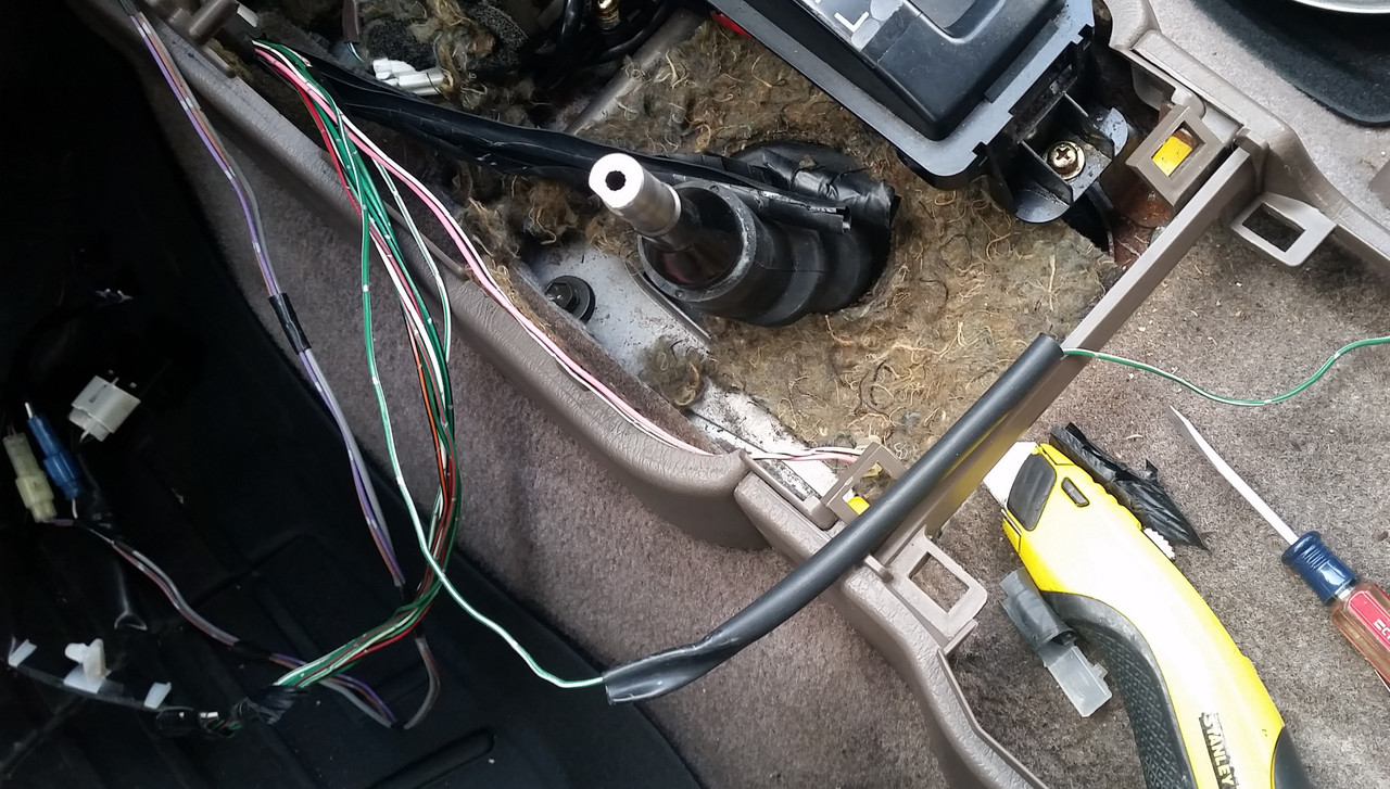


I then retaped the wires to be relocated to protect them behind the bezel:


Then I routed them up to the opening above the heater/vent controls. Here they are smack in the middle and out of focus – white 6 pin connector is the back window, black 4 pin connector on its right is the ECT:


I initially routed the security microphone and light up there as well (the two smaller harnesses right above the words “anti theft” on the radio), but later moved them to the knockout on left side of the dash:


Now you are ready to start rewiring!
 
Last edited:
Register to hide this ad
Tools

Basic wiring tools is all you need – wire stripper/cutter, wire crimper (do yourself a favor and get a good one, I use this one which is a dream - https://smile.amazon.com/Channelloc...8&qid=1514043707&sr=1-7&keywords=wire+crimper), some uninsulated butt connectors, heat shrink, and if you have one, a good heat gun. You could also use a good terminal release tool. I tried this one https://smile.amazon.com/gp/product/B0009OR906/ref=oh_aui_detailpage_o02_s00?ie=UTF8&psc=1, which did not work for me at all).


Clock

The clock connection is the easiest. Since you can reuse the clock from the ’97 (it’s identical to ‘99+), you can obviously reuse the harness and connector. So you don’t need to do anything other than pulling the clock out of the ’97 and popping it into the ‘99+ bezel. If only everything else was this easy.


Hazard Switch/Connector

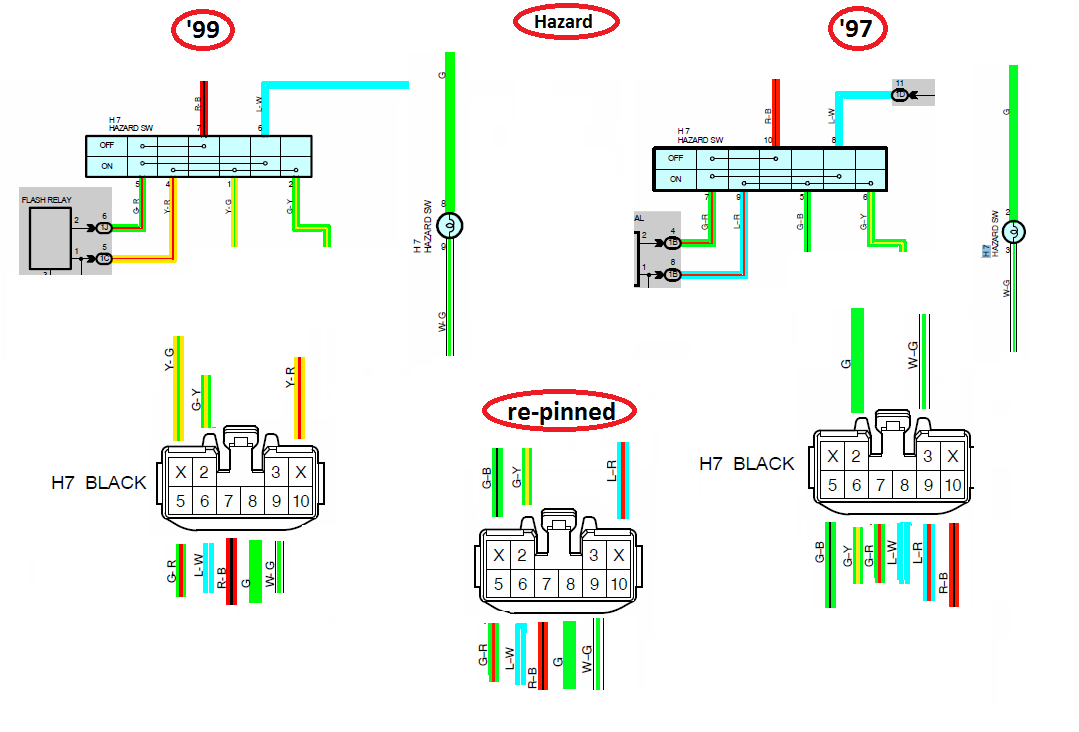
The hazard connector itself is physically identical on the ’97 and the ‘99+, H7 Black. The problem is that for some reason Toyota decided to completely rearrange where each wire goes, so you cannot plug the ’97 connector into the ‘99+ hazard switch. Well, you can, but bad things will happen. So you have to re-pin the connector, i.e. pull out all terminals from the ’97 H7 connector, and put them in different sockets to match the wiring of the ‘99+ hazard switch.

Let’s have a look at the wiring diagrams to understand what needs to be done.


As you can see above, the wiring diagrams for ’97 and ’99 are identical in terms of functions. But you will also note that the socket numbers at the connectors for each function have changed between the years. For instance, ’97 uses socket 2 for G (illumination 12V), but ’99 uses socket 8 for the same function. Similarly, the ’97 uses socket 10 for R-B (12V), but the ’99 uses socket 7 for the same function. And so on and so forth. So if you plug the ’97 harness into the ’99 hazard switch, nothing will work.

What you’ll need to do is to relocate each terminal from the ’97 connector into a socket that corresponds to the same function in the ‘99+ hazard switch. In the example above, you would pull out G from socket 2, and insert it into socket 8 of the connector – that way the illumination 12V G terminal that was in socket 2 in the ’97 will now be in socket 8, which is where the ‘99+ hazard switch expects it to be. Similarly, R-B gets pulled out of socket 10 and gets inserted into 7. In some cases, the wire colors are different from ’97 to ’99, so you have to go by function rather than wire color. For instance, ’97 uses L-R to go from switch to the relay, and the ‘99+ uses Y-R for the same function. So you’ll pull L-R from socket 9 and insert it into socket 4, where Y-R would be in a ’99.

If you continue doing this for all terminals, you’ll end up with the re-pinned configuration shown at the bottom in the picture above, labeled “re-pinned”.

I noticed that other threads have some of the wires backwards from what I show above. I believe that my diagram does a better job preserving all the intended functions, though some other techniques might work too because DC circuits are fairly forgiving (e.g. you can run current in either direction through a bulb and it will still light up).

Regarding re-pinning, I want to make it clear that at least for the novice, it was not nearly as easy as I expected. I spent over an hour re-pinning this connector, and got my hands all scratched up from pulling, pushing, and prying on the non-compliant terminals which refused to get released. Perhaps if I had more experience or the right tools, it would have gone faster, but I didn’t and it didn’t.

Here are some tips to help you along with this re-pinning. First, it would really help to have the official Toyota terminal release tool, as shown below, along with instructions on how to release the terminal:


You first have to release the white terminal lock by prying up on it. The manual says to just lift it up a little, but I ended up pulling it out completely. It was not easy or pretty, but I did get it out:


Then you have to start prying on each terminal release tab to release it. To help you out, here is a cross section of what the release tab looks like.


You need to insert the release tool from the left and push down on that black pointy tab in the red circle, to allow the silver pin to move to the right. As you push down on the tip, you simultaneously pull on the wire to get it and the terminal out. Here is the release tab pushed down, and the terminal sliding above it (in red):


I didn’t have the recommended Toyota terminal release tool, and the tool I bought (Lisle 56500) was useless. So I used a small screwdriver, which was not easy to use. I got some pins out fairly easily, but really struggled with others. Especially when trying to de-pin with the connector still in the vehicle, with limited access. So I ended up cutting apart the ’97 connector in the truck with a utility knife to release the stubborn pins, and then de-pinned the extra connector from the ’99 on a workbench with better lighting and access. That’s why I would recommend getting the donor’s hazard connector – it gives you an extra connector to play with.

Once you pulled out all the wires in this manner and reinserted them into the right sockets, it should look like in the middle of the wiring diagram picture I posted above.

Insert the white terminal lock back in:


And tape the hazard harness back up:


As another visualization aid, here is a photo of both top and bottom rows of the completed connector:


Once you do this, you’ll be done with the hazard switch. Might as well reconnect the battery at this point, plug in the ‘99+ hazard switch, and confirm that both the hazards and the turn signals work. And that you have illumination when the lights are turned on.


ECT

ECT is pretty easy, it’ll require wire splicing, but no re-pinning (yay!).

Open up the harness jacket so you can see the wires. There will be four – 12V supply (B-Y or B-O depending on model year), switched 12V to ECT solenoid and the dash “ECT PWR” bulb (G-R), and 12V for illumination (G) and illumination ground (W-G).


Here are the ’97 and ’99 ECT diagrams for comparison.


They are very similar in functionality; the main difference is that while the ’97 has a dedicated ECT connector (E4 Black), the ’99+ uses the C23 connector, which as we already discussed, is the master connector for ECT, illumination, back window, and rear defogger. So you need to splice the wires from the ECT harness to the corresponding C23 connector wire pigtails. Going by this diagram, you’ll splice E4’s G to C23’s G, B-Y to B-Y (mine was B-O, but same function, 12V), G-R to G-R, and W-G to W-G.

First cut the four wires at the ECT connector (disconnect the battery first).


Then splice each wire to the C23 pigtail (I used solderless butt connectors, others may choose to solder). Shrink wrap each connection (the top wires in photo are from the ’97 harness, the bottom wires are the C23 connector pigtails):


Then rewrap the harness with tape:


Plug the C23 connector into the combination switch, and check your work. ECT on:


ECT off:


What derailed me for a bit was that the illumination did not appear to be coming on in the combination switch when I turned the lights on. I double checked all connections, and measured 12V at the G wire, so that passed. Turned out that both illumination bulbs in the donor combination switch assembly were burned out, sending me on this wild goose chase. You’d think the least you can expect from a junkyard switch is working bulbs, right??

The ECT is now done and you’re halfway there!
 
Last edited:
Back Window

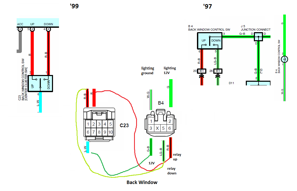
The back window switch is pretty straightforward. Here are the wiring diagrams for both model years:


Looking at what each wire does, you’ll need to splice the wires from the ’97 harness to the ’99 C23 connector pigtails as follows: LG-B to R-B, G-B to L-W, and R-B to R.

You don’t need to do anything with the ‘97’s G and W-G terminals, which are for illumination. This is because the ’97 had individual illumination supplied to each switch (ECT, back window, and defogger), so each one had the G and W-G wires for the illumination circuit. On the ‘99+, this illumination is provided to the combination switch circuit board by a single set of G and W-G wires. Since we already connected the G and W-G wires to the C23 connector when doing the ECT, we don’t need to do this again, so just tape up the back window G and W-G wires.

Here is how it looks when completed:


Test the functions of the back window using the switch.


Rear Defogger

This is by far the most difficult element of the swap – for one thing, it requires soldering on a circuit board of the ’97 defogger switch. In addition, there is a tremendous amount of confusing and contradictory information out there on which wires need to be soldered, and where – I’ve seen anything from 3, to 4, to 6 wires (hint – only 3 wires need to be soldered). Part of the mystery is that it’s not intuitively obvious how the wiring diagram of the ’97 defogger circuit board translates to physical connections and terminals that you see on the circuit board. We’ll address all that in a minute.

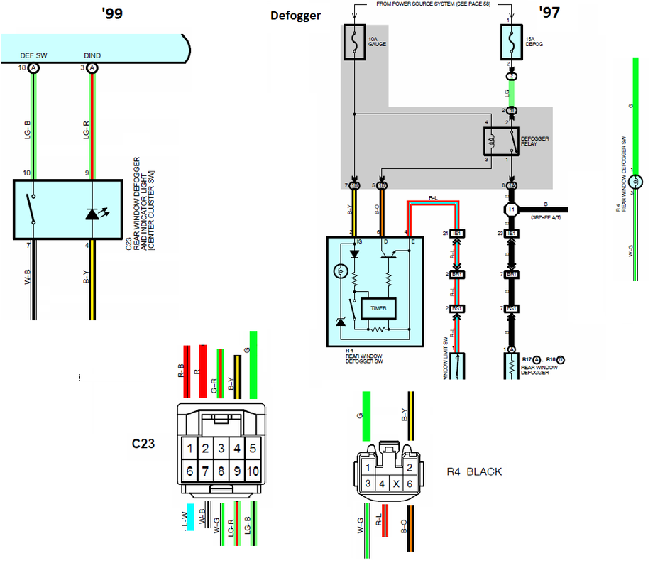
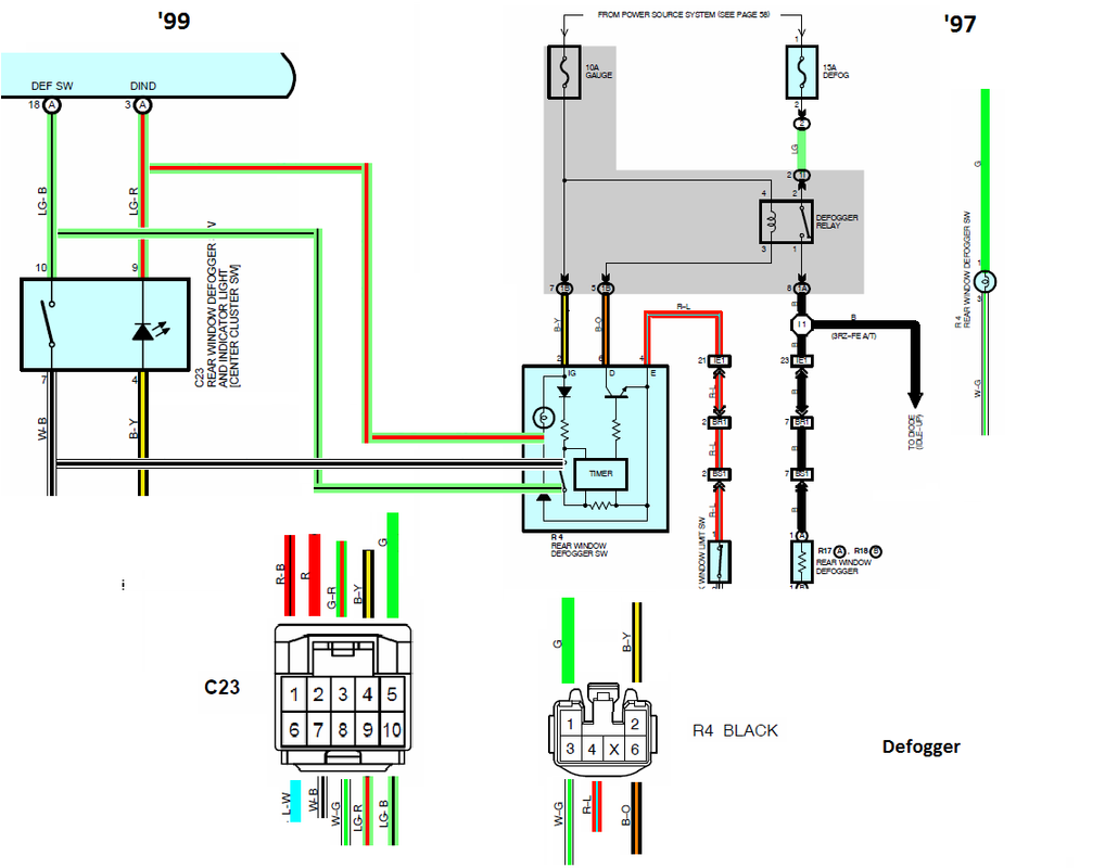
Here are the wiring diagrams for the ’97 and ’99 defogger circuits:


There is one fundamental difference between the two systems. The ’97 has all the functions and logic integrated into a circuit board which is integral to the switch itself. So when you push the switch on the ’97, you momentarily close the contacts on the circuit board, which then starts the timer, and turns on the rear defogger and the defogger indicator bulb. In contrast, when you press the ’99 switch, it simply sends a signal to the ECU (through LG-B and W-B wires), and the ECU then turns on the timer and the defogger, and sends a signal back to the bezel switch to turn on the indicator bulb (through B-Y and LG-R wires). So you need to find a way to transfer the ’99 “dumb switch” functions to the ’97 “smart switch”, since the ’97 doesn’t have an ECU.

Shown below is how to properly jumper the ’99 C23 connector wires to the ’97 circuit board terminals:


LG-B and W-B wires go to the defogger switch terminals, and LG-R wire goes to the defogger indicator bulb terminal. Three wires total. Some folks also jumper the C23 connector’s B-Y to the other side of the indicator bulb, but you don’t have to, because if you look at the wiring diagram, the B-Y wire already comes in from the R4 Black connector terminal 2, and goes right to the indicator bulb supply terminal. So you only need to jumper the return path, which is LG-R. As I said earlier, you do not need the G and W-G wires at all, since illumination to the switch panel comes from the ECT wires that we spliced earlier. I think this is why some folks splice all six wires onto the circuit board, but unless you have nothing better to do than solder, you don’t need to.

Next you need to figure out where physically on the circuit board the three wires need to be soldered. With some inspection and playing around with a DVM, you can find where the indicator bulb terminals and the defogger switch terminals are on the board – here is a photo of where they are and where you will solder the jumper wires:


Before soldering the three wires, I drilled two small holes in the back of the switch cover, and slipped the wires through:


Then I tinned the wire ends:


And off to solder! Because my soldering skills are mediocre, I decided to solder the LG-B jumper on a more accessible part of the circuit board that was still electrically connected to the terminal of interest. It gave me more room for soldering errors. Here is how I soldered the three jumpers:


Here is the look at the assembly at this point:


Slip the cover back over the circuit board:


Plug the ’97 harness back into the ’97 defogger switch, and test the defogger function using the ’99 switch (you should see the indicator bulb come on on the ’99 defogger switch, and hear the defogger relay click):


You can now tuck the ’97 defogger switch somewhere where it won’t get in the way of ducts or heater cables/levers. Here is where I put mine:


Now the hard part is behind you, it’s all downhill from here.


Cigarette lighter and power outlets

I don’t anticipate running high electrical loads through the two new power outlets, so instead of running a new wire to them, I simply spliced them to the existing cigarette lighter wiring. If I ever start running more power through them, I’ll run a larger wire from a different fuse.


Here they are spliced to the cigarette lighter wires:


Wrapping up

Reassemble all the components (duct, clock, combination switch, vents, cigarette lighter, etc). Position all the harnesses in the right place – clock connector, C23 connector, and hazard switch near top center:


Connect all the connections at top and bottom, and gently guide the bezel back in place (I wasn’t gentle enough and broke one of the vents, good thing I had a spare).

And you’re done!!


I know this was long, but I hope it helped solve some of the mystery surrounding the rewiring that is involved. Please feel free to ask any questions, I’ll try to answer while this is all still fresh in my head! Also please point out if I made any errors or typos, some of this was written up late in the evenings and after a glass of wine.
 
Last edited:
Wow! All I can say is THANK YOU for these awesome super detailed instructions...

It's tutorials like these that really add meanigful substance to DIY's and to the forum at large.

Great work!
 
Fantastic. Thank you so much for taking the time for this. As someone who plans on doing this in the future, this helps a lot. :thanks:
 
Great job on the conversion and the DIY! This should be added to the Information Threads Sticky for sure.
 
Leon, it's one thing to do something such as this, have the knowledge and skills (kudos to you), and yet still another to document it with this level of detail so others can benefit.

Thank you so much for making the time to do so!
 
Dude, awesome write up.

After paging through this, I'm so glad I just decided to keep my 97 center console and not swap in my 99 console from my donor vehicle. That just seems like a shit ton of work for some decent cup holders.

Seriously though, good job on the write up for those who want to do this.
 
Leon, it's one thing to do something such as this, have the knowledge and skills (kudos to you), and yet still another to document it with this level of detail so others can benefit.

Thank you so much for making the time to do so!

Thanks Tony! I figured I might as well give something back to the forum, especially after seeing how many links on this swap have broken over the years. One stop shop! :)
 
Dude, awesome write up.

After paging through this, I'm so glad I just decided to keep my 97 center console and not swap in my 99 console from my donor vehicle. That just seems like a shit ton of work for some decent cup holders.

Seriously though, good job on the write up for those who want to do this.

Thanks! It really did take me more time to document all this than to do the actual work, so it's not all that bad.
 
Thanks Tony! I figured I might as well give something back to the forum, especially after seeing how many links on this swap have broken over the years. One stop shop! :)

Sure thing Leon.

One of the factors in me deciding to get a 3rd gen was this community, as odd as that might sound to some. Threads like this for sure. Very helpful and supportive FAQs, DIYs, Tim & Sean's ([MENTION=120071]mtbtim[/MENTION] [MENTION=102606]infamousRNR[/MENTION]) vids...

When I had issues with a thermostat housing bolt/stud being rounded, Tim availed himself over PM, multiple times, over the weekend too. Damn nice of him to help.

Even before I purchased a 4Runner, the help and support here was impressive, including folks proactively reaching-out to me through PMs. [MENTION=95183]octanejunkie[/MENTION] was one of several such members...

There are genuinely good folks here. Leon, thanks for demonstrating that once again...

For 20 year-old rigs, this is one impressive group!
 
Last edited:
Ok, so i followed this, and everything works, besides the defrost. I have some experience soldering on circuit boards, so I am confident I didn't burn anything up doing it.

When I press the defrost button on the 899 dash, nothing happens. No indicator light, and I do not hear the relay click.

I have double checked, all wires are correct, and securely soldered to the board.

Any possible thoughts?
 
Ok, so i followed this, and everything works, besides the defrost. I have some experience soldering on circuit boards, so I am confident I didn't burn anything up doing it.

When I press the defrost button on the 899 dash, nothing happens. No indicator light, and I do not hear the relay click.

I have double checked, all wires are correct, and securely soldered to the board.

Any possible thoughts?

A couple of things to check:

- did you reconnect the R4 connector back into the '97 defogger switch?
- If yes, then check for 12V at the B-Y wire, and continuity to ground at the W-B wire
- If that fails, post a pic of the soldered circuit board.
 
Maybe a couple more to check before the ones above (the very basics):

- did your defogger work before the swap?
- is your back window closed?
- did you fully wire the C23 connector?
 
Hey Leon!
Stuck at the rear window. It don’t go up or down per your instructions. Can you confirm wire colors?

I swapped the dark green and black with the light green and black, but it now goes down but does not go up?

Any ideas?
Thanks!
 
Last edited:
Hey Leon!
Stuck at the rear window. It don’t go up or down per your instructions. Can you confirm wire colors?

I swapped the dark green and black with the light green and black, but it does not go up?

Any ideas?
Thanks!

That's because I wrote one thing but drew something else on the wiring diagram (like I said, it was late when I posted some of these :)).

Here is the corrected drawing and the words to go along (I also updated the original post):


Looking at what each wire does, you’ll need to splice the wires from the ’97 harness to the ’99 C23 connector pigtails as follows: LG-B to R-B, G-B to L-W, and R-B to R.

You don’t need to do anything with the ‘97’s G and W-G terminals, which are for illumination.

So LG-B gets spliced to R-B, and G-B to L-W. Thanks for catching this. Good luck, it should work now!
 
Last edited:
Resolved

97 harness -> 2000
Red with black stripe -> red
Green with black stripe -> blue with white stripe
Light green with black stripe -> red with black stripe
Thanks!
 

Members online

Forum statistics

Threads
278,310
Messages
3,554,080
Members
248,016
Latest member
Advally Service

Trending content

Back
Top