How to: Wiring Aux Reverse Lights

you have me really confused with your spdt thing since it doesnt have numbers.

you know the diagram with 85 86 87 87a and 30 is a double pole double throw relay right?

you do not need two relays to do this job.

LoL, [MENTION=3958]jwyshrek[/MENTION] since i say the first one looks right to me hahaha. i have no idea what is going on in the second diagram
 
gshadow325,

Technically, you are running current through the switch because you are completing a circuit...and electrons in reality flow from - to +...remember electron have negative charge.

It is all about potential (energy) at the load on whether or not sparking occurs. This is why they tell you to remove the negative battery cable when work electrically on the vehicle instead of the positive cable...less likely to arc because, in layman's terms, potential of both the negative side of the battery and the vehicle is almost same (full of electrons). But you can still get some arcing on the ground (negative) side...just not as big as on the positive side (depleted of electrons).

Anyway, sorry to go off a tangent...to the OP, I wouldn't worry about your switch being on the + side...you are just turning on a relay with very small current draw (load).

But the way the way gshadow325 described using the switch to complete the ground to a circuit is how most modern vehicles are wired. The loads have a + wire and a - wire that goes through the PCM/BCM which completes the circuit to ground. So, the computer controls the load by controlling the - side of the circuit.
 
gshadow325,

Technically, you are running current through the switch because you are completing a circuit...and electrons in reality flow from - to +...remember electron have negative charge.

It is all about potential (energy) at the load on whether or not sparking occurs. This is why they tell you to remove the negative battery cable when work electrically on the vehicle instead of the positive cable...less likely to arc because, in layman's terms, potential of both the negative side of the battery and the vehicle is almost same (full of electrons). But you can still get some arcing on the ground (negative) side...just not as big as on the positive side (depleted of electrons).

Anyway, sorry to go off a tangent...to the OP, I wouldn't worry about your switch being on the + side...you are just turning on a relay with very small current draw (load).

But the way the way gshadow325 described using the switch to complete the ground to a circuit is how most modern vehicles are wired. The loads have a + wire and a - wire that goes through the PCM/BCM which completes the circuit to ground. So, the computer controls the load by controlling the - side of the circuit.

thank you for putting down in words what i am thinking but just did not know how to say.
 
you have me really confused with your spdt thing since it doesnt have numbers.

you know the diagram with 85 86 87 87a and 30 is a double pole double throw relay right?

you do not need two relays to do this job.

LoL, [MENTION=3958]jwyshrek[/MENTION] since i say the first one looks right to me hahaha. i have no idea what is going on in the second diagram

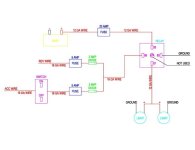
Well, from the diagram, the DPDT switch is a 'OR' gate, in a sense. The switch (if it is the right type) will allow the relay to 'turn on' with either the back up lights or with the ACC power. With this type of switch, there is no worries about power back feeding from one source to the other. The relay sources the battery power (via fuse) to the lights. I'm not sure what the diode in between the relay and switch is for. Since he is running LEDs, he probably doesn't need it, but it is good practice to keep the control source isolated from the power source.
 
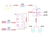
I had a spdt switch initially. Then I was told that I needed a double pole double throw switch instead as the spdt switch was wrong. So I changed it out to the dpdt. The first drawing shows, what I believe, is what you [MENTION=93434]gshadow325[/MENTION] are telling me to do. The second drawing shows what others on here are telling me to do, now minus the diode per [MENTION=3958]jwyshrek[/MENTION].
 
A SPDT takes one power source and allows it to be put to two different poles on the back of the switch at Different times, you need two inputs going to one output. since you will be using the "hot" side of the reverse circuit to switch the relay.
 
A SPDT takes one power source and allows it to be put to two different poles on the back of the switch at Different times, you need two inputs going to one output. since you will be using the "hot" side of the reverse circuit to switch the relay.

it can be also one input with two outputs. that can be triggered with a negative or a positive. relays have a ton of usages. just need to know how to use them and how they work. once the concept is grasped, its endless possibilities!
 
This is something I plan to do so I'll be watching in hopes it ends with a wiring diagram everyone agrees on!
 
By the way, thank you all for your help and being patient with a electrical novice.

Glad to help, I don't want you to mess anything up.


I had a spdt switch initially. Then I was told that I needed a double pole double throw switch instead as the spdt switch was wrong. So I changed it out to the dpdt. The first drawing shows, what I believe, is what you [MENTION=93434]gshadow325[/MENTION] are telling me to do. The second drawing shows what others on here are telling me to do, now minus the diode per [MENTION=3958]jwyshrek[/MENTION].

Thats correct. That's what I am saying to do.


This is something I plan to do so I'll be watching in hopes it ends with a wiring diagram everyone agrees on!
[MENTION=3958]jwyshrek[/MENTION] has some good knowledge, much more technical than me. I just know how to do it from experience. I didn't get to this mod yet, so I don't have a write up yet. I do plan on copying [MENTION=50591]gaterose[/MENTION] idea with putting rigid leds in the useless bumper housings. Going to order my switches first.
 
Ok, here are the two options that everyone has came up with. Sounds like both will work just fine, just a matter of preference. Let me throw another loop into this discussion. If I were to decide to run majority of this to the back, besides the switch, do you feel I would just need to increase the size of my power line from the battery?
 

Attachments

  • LIGHTS FINAL 1.jpg
    LIGHTS FINAL 1.jpg
    22.4 KB · Views: 2,135
  • LIGHTS FINAL 2.jpg
    LIGHTS FINAL 2.jpg
    27.8 KB · Views: 1,499
do this in the front, all the wires are there and then run the power to lights out back.

like i said before, i dont know what the second diagram does.
 
do this in the front, all the wires are there and then run the power to lights out back.

like i said before, i dont know what the second diagram does.

Ok, I didnt know if there would be any gain to install it in the back or having a larger gauge power wire. (ex. future lights or hookups).
 
Not sure if you have started this or not...but either in your diagram should work. I would do what is simplest to wire up.

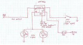
Having said that, I have the following that is the simplest, I believe, electrically based on the criteria set by me and others on this thread...now, wiring it up...maybe another issue...

So, to confuse you even more (or not) :decision:

Sorry for the crude sketch, but was busy at work...
 

Attachments

  • Untitled.jpg
    Untitled.jpg
    84.6 KB · Views: 2,827
Not sure if you have started this or not...

I have not started this as I have been searching out the correcrt parts I need. This seems like an easier way to wire everything than the previous 2 sketches I had. Just to clarify though and pardon my ignorance, the way you have it shown will have the flood lights always come on when in reverse since the NC will be that, then once I flip the SPST switch the coil flips it over to the NO position and the lights will be constant on?
 
Yes...when the relay is 'off'...power to your LED lights will be sourced from the backup lights...whenever backup lights come on...your LED lights will come on.

When you toggle the SPST switch to complete the ground circuit path...it will turn 'on' the relay and allow the LED lights to come on when the ACC is on (power sourced from battery).

So, in summary...switch off...LED lights = backup lights
switch on....LED lights = ACC on...lights will be on as long as ACC is on...if ACC is off, lights will be off (as long as you are not in reverse)...well, if I remember right, back up lights only come on if the ignition switch is on the 'ON' position (above ACC)...So, if ACC is off, lights will be off.

There should be no issue of mistaking leaving the LED light on with the vehicle off.
 
Last edited:
They look ok...however, if you intend to use the indicator light on the switch...you'll have to move the switch from pin 86 side of the relay (ground) to pin 85 side of the relay (ACC on hot)...in order to have power for the switch indicator light.

By the way, if you have an auto part store near by (autozone, orielys, etc.)...you should be able to pickup the necessary items there...sometimes even Walmart has them.
 

Members online

Forum statistics

Threads
278,312
Messages
3,554,089
Members
248,016
Latest member
Advally Service

Trending content

Back
Top