I'm getting a front swaybar disconnect system built, I need a donor bar

wfo9

New member
I've been wanting to do this for a long time, but I just recently got the motivation to actually get it fabricated. I thought about doing it on my own or with a friends help who is a more skilled welder, but then I decided to not mess around and let professionals do it.

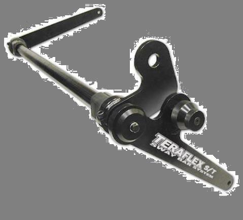
The design is a single sided disconnect system. Two bolts on the bar end and then a pin on the drivers side link and your swaybar is fully disconnected and there is no noise or contact with the CV boots.... You just reverse the process to put it back on (maybe 5 minutes while airing down/up).

If you click here you will see a few versions of the basic design. This will be a little more beefy than these, but follow the same basic design.
https://www.google.com/search?q=fj+...a=X&ei=CYssVZ7yB8LngwSU74GADA&ved=0CAgQ_AUoAw


You can then either run extended links in the rear (which provide plenty of articulation) or just completely remove the rear if you want that last inch or so.

The general design is very proven, but I'm trying a local fabricator plus one I found in Cali to see who's final result is best. I'm taking all the risk here... but once the product is proven and all the kinks are worked out, I'll help anyone else who wants to get the same thing built for themselves. I won't be trying to make any money off this. The price will most likely be between 200-350.

I could use some help though, I need a donor sway-bar. Mine is already in process locally. I know some of you have no plans to ever run your front again. If so, I will pay you to ship it directly to the fabricator in cali or to me if that is closer....

This might save me ~$150...

I'm also looking locally for one. So please PM or post here if you have one. I will post plenty of info on the results once they are done.
 
Register to hide this ad
I know some others have tried. So I will subscribe to watch your effort. Design looks good. Almost would make me run a front sway bar again.......almost.
 
Long overdue and needed. Only comment is to take care on its ease of connecting it because on Jeeps for example it can be a real PIA.

Good luck!
 
I think this will be very easy to disconnect and very strong... but I won't know for sure until I have it in my hands and can test it thoroughly..... I have done quite a bit of research and all indicators so far are 100% positive, but there can always be issues in construction and materials.....

I feel it is a huge win to have a product like this available for the 5th gens. So much so, that I'm willing to spend some money on trying 2 different designs.

Anyone who has removed the front sway-bar knows there is no going back, the improvements off-road are undeniable. Although, the downside on the road is not extreme... it is also not ideal by any stretch of the imagination. Case in point, I won't let my wife drive my t4r without the the front sway on.

If it works out, we could possibly do a group buy on here... But I would prefer to make sure it is 100% functional and rock solid before attempting that.

Again, I have nothing to gain here except making my truck (and possibly yours) more on/off road capable.

I'll eventually find or buy another bar, but it sure would make things go faster if someone had one available.
 
I'm not sure I totally understand this. You cut the sway bar, weld on a set of brackets, then add end links - one side with a disconnect? Is that basically the idea?

What is driving the need to cut off the arm? Can't you simply install a sway bar link disconnect?

Or in the alternative, why not have the cut joint release and articulate freely?
 
Last edited:
Interesting post!

I had swaybar disconnects on my truck many years ago, this is the kit that I had (when front Range Offroad was making them, its now Persson's Offroad I think):

swapdis.jpg


While it was relatively easy to disconnect, I would have to tie the bar up so it wouldn't get banged around on the trails. Also, it was sometimes a royal pain to put the pins back in if I wasn't on perfectly level ground. I eventually ended up just learning to drive without it connected at all, and finally removed the whole sway bar altogether.

I still have the set under my workbench, not sure how the 5th gen bars connect as I haven't really looked under the 4r since I got it (don't plan on lifting another one of my vehicles, already got a perfect offroad truck!), but if this old kit could be used/modified to work with the 5th gen bars, I think it would be much cheaper to do as the above style is only a hundred bucks online right now.

Do you have some photos of the sway bar endlinks by chance? If I see the ends, I can determine if this kit would be "modifiable" to work with the 5th gen bars.
 
Disconnects work on the rear bar but not the front for the T4R. You can tie the rear out of harms way really easily. However, the front is a different story. There's no way to have a simple link disconnect and tie the sway bar to avoid damage.

If you try this, you are guaranteed to at least tear your CV boots if not more depending on how it gets fouled up. Just too much going on with the IFS front end. A guy we wheel with tried it once based on his jeep experience. I don't think he made it 2 hours before both CV boots were mangled.
 
Disconnects work on the rear bar but not the front for the T4R. You can tie the rear out of harms way really easily. However, the front is a different story. There's no way to have a simple link disconnect and tie the sway bar to avoid damage.

If you try this, you are guaranteed to at least tear your CV boots if not more depending on how it gets fouled up. Just too much going on with the IFS front end. A guy we wheel with tried it once based on his jeep experience. I don't think he made it 2 hours before both CV boots were mangled.

My thoughts exactly. I sure hope the OP can pull it off though. I for one, will be pulling the front sway bar off completely and calling it a day. Just need to get around to doing it.
 
The links are not the challenge on the 5th gens. Those are super easy to build...

That is what [MENTION=809]fattire[/MENTION] is saying....

The challenge is being able to keep the actual bar ends from contacting the CV boots. It can be accomplished by creating a single sided disconnect as pictured below. The driver side is disconnected and the passenger side stays in place, but becomes 100% ineffective.

539037197_qSpee-M.jpg


For the rear, it can either be completely removed or you can just install extended links and tune its behavior. The rear does not kill offroad performance like the front IFS does... Plus, running on the road with only the front is pretty darn stable. If you wanted to go balls out.. you could run a rear tire carrier and this https://www.allprooffroad.com/fjrearsuspension/fjc-rear-swaybar.

Another possibility for the front is creating sliding links, but they are a little noisy while running open (and I dislike noisy stuff).

For those planning to remove the swaybar for good... Yes, this works and you get use to it. However, it is also not ideal for everyone. I don't trust others driving my truck like this and I would much perfer to have the swaybar working when on the road. It seems like anyone in their right mind would rather have the stability. It's a trade off not to have it on, so this is an attempt to not have trade offs. (Except for the connect/disconnect time)

As far as connecting on uneven terrain... That still might be a problem. Not sure why you would need to do that. Flat ground would be the place to get connected and aired back up.....
 
Last edited:
The double disconnect in the above picture will be great and the CVs won't be anything to worry about. Only thing I am wondering is with larger tires would you rub the connection?
 
For those planning to remove the swaybar for good... Yes, this works and you get use to it. However, it is also not ideal for everyone. I don't trust others driving my truck like this and I would much perfer to have the swaybar working when on the road. It seems like anyone in their right mind would rather have the stability. It's a trade off not to have it on, so this is an attempt to not have trade offs. (Except for the connect/disconnect time)

Definitely a worthy point. I should have mentioned that my 4Runner is no longer my daily driver. If it was, I'd be keeping the sway bar in. Even for future expeditions that I have planned, I'll have both sway bars in - this is where having a quick disconnect shines.
 
If the sway bar simply pivoted at the point where the two bolt connection is - would that both protect the CV boots and allow everything to stay in place? Basically if you had one through bolt and one pivot pin in place of the two bolts, and removed the remaining bolt so just a pivot pin were allowing everything to move. Of course you'd move the two mounting plates back to the 90* bend rather than part way down the arm.

Basically this modified for the stock sway bar:
sway.JPG
 
[MENTION=106176]wfo9[/MENTION] I would recommend you read this thread:

http://www.toyota-4runner.org/4th-gen-t4rs/138892-4th-gen-disconnecting-sway-bar-set-up.html

The two biggest points you need to impart on your fabricator if they already don't have experience with this (and the biggest mistake I see a LOT of those FJ disconnects make) is that you want to retain as close to or the same metallurgy in the sway bar as you start out with. What I mean by this is that too many guys just slap on mild steel bars from Home-Depot as if it magically takes on the properties of the 4130 (rough guess based on my research) ChroMoly. Mild steel deforms and has different strength and characteristics than the material the sway bar is made from, if you do not match the material closely you've ruined the sway bar. The second issue is that when welding 4130 or 4140 ChroMoly Steel in such thicknesses you need to properly pre-heat and post-heat the metal as well as use the appropriate filler rod, failure to do so will result in cracks and change in the metallurgy of the metal; thus again ruining the sway bar's designed properties.

When designing my unit for the 4th Gen If felt that using lug nut studs like previous designs was too much of a hassle to bolt-on and off without a proper torque wrench (of which you'd have to still calculate the torque values.) My design ended up working in practice, but because of some stacked tolerances I didn't account for due to a lack of a dynamic model of the suspension it bound up with the quickly made heim joint link I made (I actually machined a bolt-on post for the heims to connect onto instead of a two part link like the above picture, it kept the dangling parts to a minimum.) Most likely eventually I will get around to making a second prototype when I finally do get some time and space; but honestly look at the welding requirements and other issues it might end up better to find a shop that extrudes/bends tubing and have them custom make you a sway bar in two parts and machine it down.

One more thing to note is that a lot of those designs place the bolts and connection within the scrub angle of the tire, meaning that the sidewall could rub up against the joint under full lock (part of the reason I pulled my design further back at the bend to avoid that issue as much as possible.)

Post Note-

I do regret not taking pictures of the set-up bolted on the vehicle and a close up of the bolt-on piece I machined. :(
[MENTION=118321]Jetboy[/MENTION]

I had a person mention a similar design in my thread and it was a beautifully machined work of art with a camlock system similar to manual hubs on the ends. The issue is that most of those set-ups are on Jeeps that use an extremely plain sway-bar that is roughly a "U" shape. On the 4Runners, Tacomas, and FJs, the bar is very bent up for clearance of various components; to accomplish a similar goal would require a custom center bar that is machined, then bent at precise angles as well as custom outer bars machined and bent at the proper angles.
 
Last edited:
Yes, the material is complex to weld that is why I'm having pros weld it and stress relieve it properly... Scrub angle should be fine as measured. But I will have to verify once it is all done.... Also, the bar does not see a torsional load where the connection is being made.

I might end up spinning my wheels a bit on this... but I'll take that risk for now. It might take a few tweaks to get it right.

And yes, the bar has to be bent in all types of interesting ways to clear everything. I wish something simple like Jetboy posted would work on a 5th gen.
 
Yes, the material is complex to weld that is why I'm having pros weld it and stress relieve it properly... Scrub angle should be fine as measured. But I will have to verify once it is all done.... Also, the bar does not see a torsional load where the connection is being made.

I might end up spinning my wheels a bit on this... but I'll take that risk for now. It might take a few tweaks to get it right.

And yes, the bar has to be bent in all types of interesting ways to clear everything. I wish something simple like Jetboy posted would work on a 5th gen.

I wouldn't worry so much about torsional load as much as other forces acting on dissimilar metals in that area. You have vertical and longitudinal forces due to the many bends and so on, my concern would be the sway bar weakening, cracking, and/or bending at those weaker metal joints in regards to the before mentioned jobs that are not matching up the metal correctly. The benefit is that mild steel is much easier to work with than using the more than likely ChroMoly that is used in the sway bar, as my project required carbide tool bits to correctly machine (I could have uses HSS, but the machine I was working on did not have a coolant set-up so it would have been painful to attempt with just a brush and oil.)

My 4th Gen's (like much of the newer J150 platform many of the older mounting points are unchanged from the J120 platform) sway bar has no paint left on that bend and about 2-3 inches behind the bend from my 285/70R17's rubbing on it at full lock and under compression at times. That would place it roughly near/over the first stud of your disconnect, even welding wings like many have done on the ends might chew up the tires if you didn't chamber the edges and make sure your installed stud and nut height is below your wings (extending the wings too far out exacerbates the issue) when doing tight obstacles. It's a minor concern and it probably won't destroy tires, but it could be something to be aware of during the design process.
 
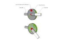
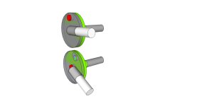
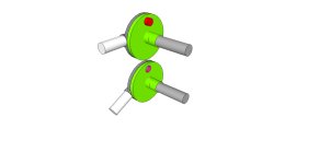
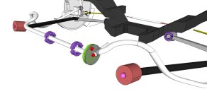
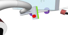
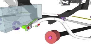
I don't think I was describing what I was proposing to build correctly. Sometimes pictures are worth a thousand words... Also FWIW I would be very careful in design to specifically avoid anything that requires tight tolerances like the pins in some designs. They will wear out and it will complicate manufacturing to have hardened bushings to deal with this issue. KISS.

Drawing 1 would replace the new bolt on joint and rather than remove, just unpin.

Drawnings 2-4 better reflect a more appropriate location for a disconnect. Just outboard of the factory bushing. I've done a quick mockup with an off-the-shelf front suspension to show where it would sit. It should work normally with the cut end of the factory sway bar so all the curves are in all the right places.

Just food for though. I have KDSS - so I have no intention of ever modifying mine unless I end up down the road with a solid axle up front.
 

Attachments

  • Sway Bar Disconnect 1.jpg
    Sway Bar Disconnect 1.jpg
    90.6 KB · Views: 745
  • Sway Bar Disconnect 2.jpg
    Sway Bar Disconnect 2.jpg
    85.2 KB · Views: 734
  • Sway Bar Disconnect 3.jpg
    Sway Bar Disconnect 3.jpg
    78.8 KB · Views: 684
  • Sway Bar Disconnect 4.jpg
    Sway Bar Disconnect 4.jpg
    64.6 KB · Views: 817
That's similar to some of the jeep designs I have seen and works well for those applications. Something you would need to consider is that the bend you're talking about modifying is directly in the scrub angle of the tire, which means if it has corners/sharps/protrusions they will get caught/rub/possibly damage the tire/ect. on turns; where as on the Jeeps their bars are not subject to that scrub typically. It's a sound design though. I would love a cam/lever design like that if it could be done without affecting scrub angle/turning radius to protect the tires & joint. Though again with all the bends in our sway bar, you'd probably need a more dynamic set of measurement for the front suspension because even with such a design it may bind up/flex in undesirable ways and impede travel/flex.

Tight tolerances are subjective in the automotive world, depends on the design and applications. In my design the tolerances were rather loose by most machining standards (I think I went with about .005~.010" between the pin and the bore), but the idea wasn't so much super tight tolerances as it was taking advantage of leverage.
 
Just to clarify.

I thought about many designs...and I would love to come up with something really innovative, but I have a day job and don't wan't to spend a bunch of time on it. The space constraints make it a major challenge.

The idea was simple. Keep it as simple as possible, talk to people who have done it and find out what works, get craftsmen with many years of fabrication experience to build it.

People have been running similar designs for 5+ years with no issues.

It might not work out perfectly. If not, I'm a few hundred bucks in the hole. No big deal.
 
I was thinking fabrication of this would could be a lot easier than the removable link style. My family owns a metal fab shop that manufactures among other things some farm and mining equipment. So I tend to view these things from the fabricator's point of view.

By sleeving a portion of the bar you won't need heat treating or special materials. Pocket weld near the inner part of the sleeve would hold it. The maximum loading is taken at the rim and should remain unchanged by the welding an inch or two away. And the parts are probably scraps that most shops have sitting on a shelf. The disc set could sit at the frame rail, but I don't know if that clears or not. Of course it could go inboard of the frame rail just inside past the bushing as well if you can still access it there. Anyway I was kinda dreaming up something that every backyard mechanic with a band saw and mig welder can build. - something I can fab in a couple hours in my garage.

I can understand going with something well tested. I'm sure it works. Let us know how it turns out. Good luck.

Edit:

Just wanted to add a couple pics to show how you'd clear the tire at steering lock - and a more realistic placement of the disconnect pin.
 

Attachments

  • Sway Bar Disconnect 6.jpg
    Sway Bar Disconnect 6.jpg
    54.4 KB · Views: 619
  • Sway Bar Disconnect 5.jpg
    Sway Bar Disconnect 5.jpg
    96 KB · Views: 662
Last edited:
Something very elegant could definitely be done, but I think it would require a thinner bar to deal with all the space constraints.... These things just tend to be out of reach for most of us. Time is money....
 

Members online

Forum statistics

Threads
278,316
Messages
3,554,120
Members
248,016
Latest member
Advally Service

Trending content

Back
Top