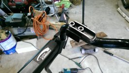
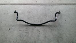
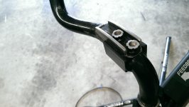
I'm getting a front swaybar disconnect system built, I need a donor bar

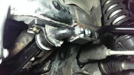
I have not had much time for this lately.. lots of stuff going on with the family.... but got the first rev done and started some test fitting tonight.

I still need to finish making the hardware. Planning on spline drive bolts but need to get my lathe out to get the clearance I want... also need to experiment with some other options.

$150 invested so far and it looks very promising. Tolerances are super tight (which is good and bad) I might need to loosen it up a bit to make removal/install easier (it require a hammer at the moment).

I also still need to come up with the link disconnect.

Anyway, here is a pic. Will be interesting to see how it clears everything. Might have lost 1/4 inch of scrub angle at most. Appears to be extremely solid but road testing will be required...

If anyone has a link quick disconnect lying around... let me know.
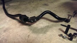
 

Attachments

  • sway.jpg
    sway.jpg
    92.9 KB · Views: 1,655
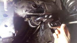
Quick update on this. I installed the swaybar and ran around town with it on today. I also took it on and off a few times...

Results so far are fantastic.
  • Body control is great as expected.. just like having a regular swaybar
  • Disconnected it flexes just like no sway bar on
  • Removal takes minutes (maybe 3) much faster than airing down
  • Installs in minutes (about the time it takes to air up 1 tire)
  • No tire rubbing on scrub angles so far, looks like plenty of clearance

Still a little concerned about long term durability, but really no way to verify that without more use.

It's nice not driving a boat on the road ;-)
 

Attachments

  • disco1.jpg
    disco1.jpg
    84.3 KB · Views: 575
  • disco2.jpg
    disco2.jpg
    74.7 KB · Views: 569
Last edited:
There are plenty of threads (about .40" of contact). It is a canonical seat (so most of the contact is below the surface). I'm torquing to ~80 ft /lbs... The studs are wheel studs.

The bolts are just much bigger than necessary (I may machine them down some more). I had some very small open spline drives on there that I machined, but they felt too flimsy. I want to be able to take them on and off with an impact gun with no worries.
 
Last edited:
There are plenty of threads (about .40" of contact). It is a canonical seat (so most of the contact is below the surface). I'm torquing to ~80 ft /lbs... The studs are wheel studs.

The bolts are just much bigger than necessary (I may machine them down some more). I had some very small open spline drives on there that I machined, but they felt too flimsy. I want to be able to take them on and off with an impact gun with no worries.

Looks like a great setup, i see what your saying about the contact. I guess i am just old school, i have trouble if i can't see the end of the bolt at least flush with the nut. LOL
 
Looks awesome!

The conical seats and lugnuts is great solution to that joint. I think that design will last for a very long time compared to the other versions that rely on precise machined fit.
 
Why didn't you just get KDSS?! Haha - had to say it.

Looks good. It's nice when a project comes to completion. Keep us posted on long term operating and durability results.
 
[MENTION=106176]wfo9[/MENTION]. Any updates on these?
Yea, sort of..

It worked out perfectly for about a month and then I took it offroad without disconnecting it and drove a little too fast LOL. It bent outboard a tad. The fix is to gusset it for that type of load.

However, I had a major shoulder injury/problem so all work on the truck has been on hold.

Might have an updated setup in the next few weeks.
 
I've been working on the second rev... This has taken quite a bit of time.

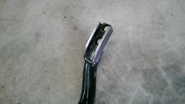
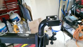
This one includes gussets on the disconnecting arm for lateral outboard loads at the connection point. The challenge was fitting bolts with the gussets, so I machined some spline drives on the lathe.

Still need to verify clearance on the truck, but it should be fine. since I measured all my scrub angles beforehand.

I took pictures before painting, since it is really hard to see when it is all black...
 

Attachments

  • IMAG0074.jpg
    IMAG0074.jpg
    137.2 KB · Views: 475
  • IMAG0076.jpg
    IMAG0076.jpg
    134.2 KB · Views: 480
  • IMAG0078.jpg
    IMAG0078.jpg
    132.2 KB · Views: 501
  • IMAG0081.jpg
    IMAG0081.jpg
    136.5 KB · Views: 467
  • IMAG0080.jpg
    IMAG0080.jpg
    117.9 KB · Views: 502
if you need another bar to play with my front one is laying around my parents house somewhere not being used.

Thanks for the offer, but I'm hopefully done with this project for a while. Also, the 5th front bars are a bit different than the 4th gens (if that is what you have).

I ended up just taking one approach and working with my original bar. I might want to try some more things this fall as I plan to get access to some CNC equipment..... Eventually, I would like to come up with something a bit more elegant, but I think this will get the job done for now.
 
As much as I'd like to run a front sway bar again and would like to get something that could, like this. I still can't lol. I'm thinking of something along the lines of this. Just cutting the sway bar in the middle and adding 4"(for my set up) to the middle of my sway bar.
 
@WFO9

The second revision looks good, the spline drive nuts are an interesting solution. Though aside from what I mentioned before about metallurgy differences earlier in the thread, that thread engagement seems very light.

Good looking bar none the less! Be interesting to see what other design avenues you take later down the road. (Making me want to get around to revisiting my original design.)

As much as I'd like to run a front sway bar again and would like to get something that could, like this. I still can't lol. I'm thinking of something along the lines of this. Just cutting the sway bar in the middle and adding 4"(for my set up) to the middle of my sway bar.

I don't know if you forgot to post a link or what, bu I don't see your example. :(

I had thought about doing something like this:

66732-lg.jpg


As one member pointed out in my thread, the splined central torque shaft would be a great solution; were it not for the fact that the central portion needs two bents to offset the bar for clearance! I'm not entirely sure how effective it would be to induce bends in the bar as it would require precise bending and heating/cooling to retain the strength of the hardened steel. The other challenge would be the side arms and cam lock as the side arms can't just be a simple machined plate and the cam lock is right in the scrub angle of the sway bar.
 
[MENTION=66389]BlackWorksInc[/MENTION] I'm running a long travel set up in the front and it increased my track width 4" so a stock sway bar no longer fits. I've been thinking of the Currie Antirock at times.
 
@WFO9
The second revision looks good, the spline drive nuts are an interesting solution. Though aside from what I mentioned before about metallurgy differences earlier in the thread, that thread engagement seems very light.

Thread engagement is fine, It is just deceiving in the pictures due to the seats being so deep.

I'm pretty confident this will hold up to typical use (on road and light off-road). What I'm not confident of is it holding up to rock crawling conditions while connected. I've bent links into noodles before doing that.

There are things I would like to have done differently, but I've got other higher priorities projects at the moment.

The bends and space constraints with this bar make it a huge challenge to come up with a really elegant design.

Anyway, I'll report back in a few months after more testing.
 
Interesting design. So you completely remove the driver's-side arm and link?

Just curious, but do you know how much it would cost to ship a sway-bar? One option would be to take your donor bars and pre-fab everything. Then sell with a "core" charge which gets refunded if the buyer sends his unmodified OEM bar back to you.
 
Interesting design. So you completely remove the driver's-side arm and link?

Just curious, but do you know how much it would cost to ship a sway-bar? One option would be to take your donor bars and pre-fab everything. Then sell with a "core" charge which gets refunded if the buyer sends his unmodified OEM bar back to you.

Yea, removal is very easy. Park on somewhat even ground then I just turn the wheel to full lock passenger, reach behind the wheel and remove the link bolt on the back of the spindle.

Then I turn the wheel straight, (or lock to driver) and remove the two spline drive bolts on the bar. Then that driver side arm comes right out. The truck then effectively has no sway bar. The connected side simply moves without any torsional resistance whatsoever.

I have no plans to turn this into a business venture.... I have an unlimited supply of much more profitable work at my day job....LOL
I am however willing to help someone replicate the same thing (based on what I have learned). I think it is still too early to call it a complete success... More testing time needed….

It's been a challenging endeavor. There is nothing really easy about this. Lots of curves, bends, and unknown materials and loads.
 

Members online

Forum statistics

Threads
278,316
Messages
3,554,120
Members
248,016
Latest member
Advally Service

Trending content

Back
Top