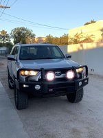
LED LIGHT BAR INSTALL on a 2014 T4R

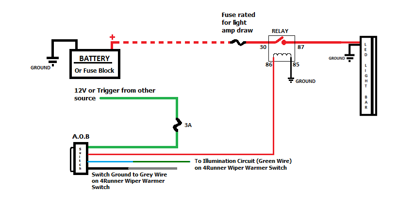
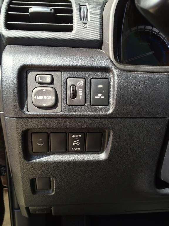
Ok, lighting should only be on when the light switch is turned on, on the stalk. Prolly have the two of the wire not in the correct location on the switch. I seem to remember some of then having been shipped out like that. Check wire color and location on switch referenced in my diagram. ( I just checked my extra switch wires and they are as indicated on the diagram. )


That wiper warmer switch should only illuminate when you turn your lights on, not when the ignition is turned on.
Then the little light bar indication above the wiper etching on that switch should light when the wiper warmer switch is depressed and go off when depressed again or until it times out.

The blue and black wires are in the correct locations on the switch per the sketch, but the green and red are reversed. Here’s my switch with the red wire being the top. Middle pin is the empty one of the 5.

Further info:
Key on, stalk off: upper half of switch is lit, wiper button off
Stalk DRL: upper half switch is lit, wiper button off
Stalk Parking: top and bottom switch lit, wiper button lit
Stalk headlights: tip and bottom switch lit

Operating the lights does not effect portions of the switch lighting or not at any point. Again, dimming works as it should.


http://imgur.com/vEcSLpd
 
Last edited:
The blue and black wires are in the correct locations on the switch per the sketch, but the green and red are reversed. Here’s my switch with the red wire being the top. Middle pin is the empty one of the 5.

Further info:
Key on, stalk off: upper half of switch is lit, wiper button off
Stalk DRL: upper half switch is lit, wiper button off
Stalk Parking: top and bottom switch lit, wiper button lit
Stalk headlights: tip and bottom switch lit

Operating the lights does not effect portions of the switch lighting or not at any point. Again, dimming works as it should.

http://imgur.com/vEcSLpd


suggestion: switch pin locations and wire as per diagram.
 
Sure enough I swapped my green and red wires and the illumination is working properly (and so are the lights).

Takeaway is that the Saker diagram most importantly shows the correct pin position top to bottom of the AOB switch and the wire color is secondary thanks to some suspect qc by AOB. I obviously did not realize the diagram was also showing actual wire positions not just color.

Thanks for taking the time to respond.
 
Sure enough I swapped my green and red wires and the illumination is working properly (and so are the lights).

Takeaway is that the Saker diagram most importantly shows the correct pin position top to bottom of the AOB switch and the wire color is secondary thanks to some suspect qc by AOB. I obviously did not realize the diagram was also showing actual wire positions not just color.

Thanks for taking the time to respond.

I didn't use Saker's diagram, but I can confirm that the latest round of AOB switches coming out have the wire colors reversed (Green and Red) from those that were produced when this write up was written.
 
Sure enough I swapped my green and red wires and the illumination is working properly (and so are the lights).

Takeaway is that the Saker diagram most importantly shows the correct pin position top to bottom of the AOB switch and the wire color is secondary thanks to some suspect qc by AOB. I obviously did not realize the diagram was also showing actual wire positions not just color.

Thanks for taking the time to respond.

I can also confirm AOB switched the colors. My switch came with an updated wiring diagram reflecting the change. Does not seem to be a QAQC issue.
 
Sure enough I swapped my green and red wires and the illumination is working properly (and so are the lights).

Takeaway is that the Saker diagram most importantly shows the correct pin position top to bottom of the AOB switch and the wire color is secondary thanks to some suspect qc by AOB. I obviously did not realize the diagram was also showing actual wire positions not just color.

Thanks for taking the time to respond.
No worries, glad you got it sorted out. :)


I can also confirm AOB switched the colors. My switch came with an updated wiring diagram reflecting the change. Does not seem to be a QAQC issue.

So you have documents showing red & green switched in the pins and red connecting to 12V and the green connecting to the #86 on the relay?
Hope I am understanding that correctly.... :)
 
So you have documents showing red & green switched in the pins and red connecting to 12V and the green connecting to the #86 on the relay?
Hope I am understanding that correctly.... :)

Exactly correct. It seems AOB made an intentional change.
 

Attachments

  • backgrounder (1).jpg
    backgrounder (1).jpg
    137.7 KB · Views: 824
I didn't use Saker's diagram, but I can confirm that the latest round of AOB switches coming out have the wire colors reversed (Green and Red) from those that were produced when this write up was written.

I had the same issue with mine, I wired my second switch up the same as my first and ended up having to reverse those 2 wires to get the switch to work properly
 
LED LIGHT BAR INSTALL

The purpose of this write-up is to help people that are interested in installing a light bar behind the grill of their 2014 Toyota 4Runner. I will list the parts used as well as pictures.

For the cleanest install, I'd recommend a full relay harness. TRS makes a nice one, and it's actually got two relays which might be nice if you want to add another light in the future.
HD Relay: H1/H3 - Wire Harnesses - Components
To make things easy, I'd also get these and I'll explain why later:
9006 Extension Cords - Accessories from The Retrofit Source

If you go with a relay harness like the one above, you'll simply connect the power connector to the battery, connect the ground connector to a ground, run the light plugs towards the light in the grill and connect the switch wire to the signal wire in the relay harness. The first three are very easy, the last one takes a bit more work.
In this case, the relay harness has an H1/H3 and you won't need that, so you can cut that connector off. When you cut that connector off, the wire left (orange insulated wire) is where you'll connect the switch wire to. Of course, you'll need to extend that wire from the switch to wherever you mount the relay harness. The other wire (black insulated wire) is a ground wire that will need a terminal.

Now, you'll need to connect a wire from the high beam or fuse to the trigger wire on the switch to provide it with power. This is the questionable part. By connecting to a fuse, you'll have to hit the switch every time you want to turn the lights on. Honestly, it's a pain in the butt if you plan on using your lights on back roads at night. Connecting to the high beam is much more convenient since you can leave the switch on and every time you turn the high beams on, the eBay bar will light up without having to hit the switch. Very handy. If you choose to connect the eBay bar to a fuse and not the high beams, you have two choices. One, you connect it to a fuse that's always hot. Two, you connect to a fuse that is only on when the ignition is on. The advantage of the first option is that you can turn the light on any time, whether the truck is on or off. That's also the disadvantage because it's easy to accidentally leave on. I'm going to suggest you run the trigger wire on the switch to the driver's side headlight and connect it to the high beam wire. (Don't forget to install a Mini Waterproof 3 or 5 Amp In Line Standard Blade Type Fuse Holder on this circuit!) This should work whether you have the DRL or not.

This should give you an operational switch, an operation harness and the only thing left is to connect the light to the relay harness. This is where those 9006 extension cords come in. Plug those extensions into the end of the relay harness at the light, cutoff the part you don't need and splice your light's wires into that extension cord. Basically, it'll leave you with a nice clean plug so it's easy to remove the light in the future.

I'd do all of this in a few stages. You'll need two provide two wires of your own, so you can simply use a speaker wire or something like that that already has two wires in it. They're both going to the switch on one end, and close to the headlight on the other. Run that wire first, through an existing rubber grommet on the firewall near the master cylinder. Do the switch next. Relay harness after that. Attach the lights. Fire it up and make sure everything works. Finally, clean up the wiring, make it pretty, attach the relay where you want it and enjoy the lighting.

Things you'll need:

The switch. Mine came from AirOnBoard USA
TOYOTA 4RUNNER Replacement Switches -Air On Board
The relay harness I linked to, or something like it.
A length of wire as discussed. I used 18-2 gauge stranded speaker wire.
At least three 18-22 gauge t-taps (one at headlight, one at illumination wire on existing switch in dash) A few extra won't hurt since those things are temperamental at best.
Butt connectors, at least 5 for the new switch ( (1)ground, (2)power and (2)trigger wire (solder and heat shrink tubing is preferred if you're capable)
Mini Waterproof Amp In Line Standard Blade Type Fuse Holder (comes with a 10 or 20 amp fuse change to a 3 or 5 amp) This goes on the trigger circuit!

I hope this help someone wanting to install something similar!


Simple Aux Light Wiring Dia for 4Runner
196154d1458356165-2014-2016-behind-grill-light-bar-mounts-aux-light-wiring.png

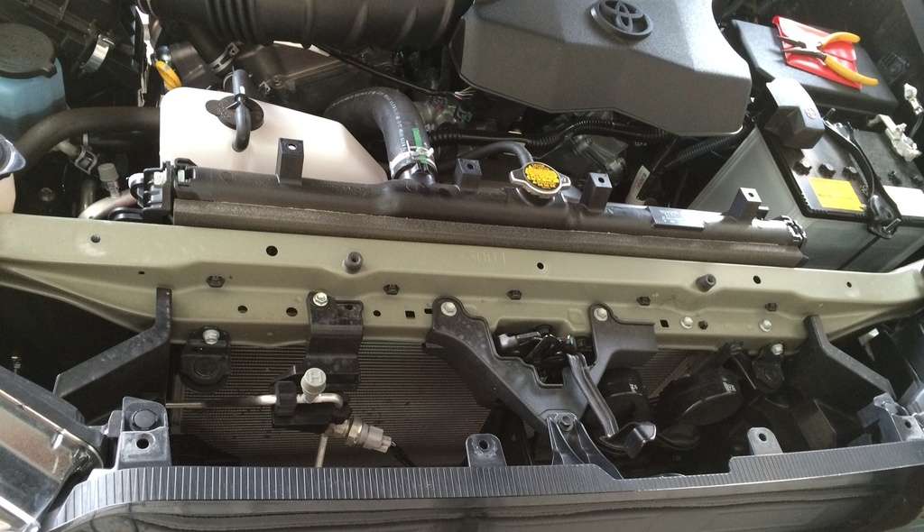
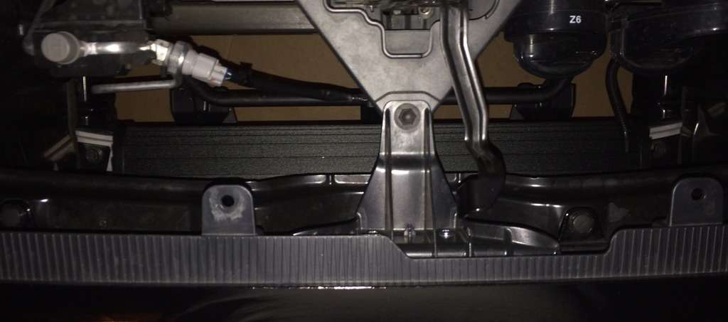
Upper Access Cover - Removed
fjkr.jpg


Lower Access Cover - Removed
13xw.jpg


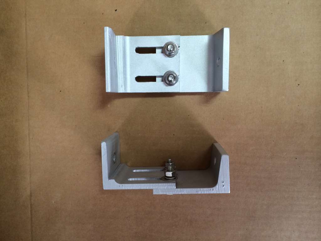
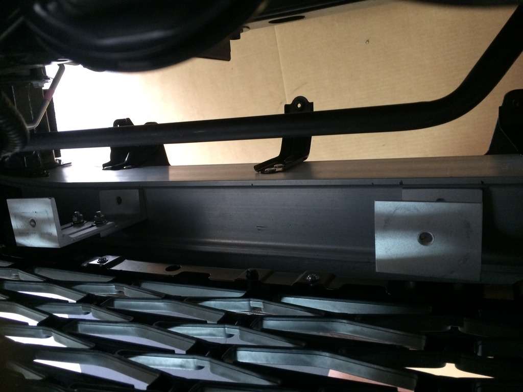
Aluminum Brackets Fabricated
z3su.jpg


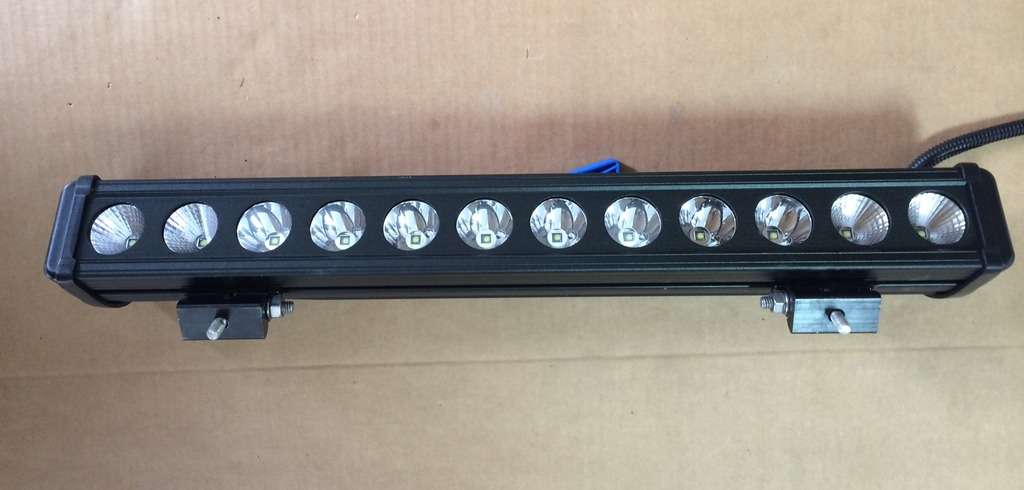
eBay 22inch 120 Watt LED Light Bar
kshw.jpg


Positioning Brackets
ac4e.jpg


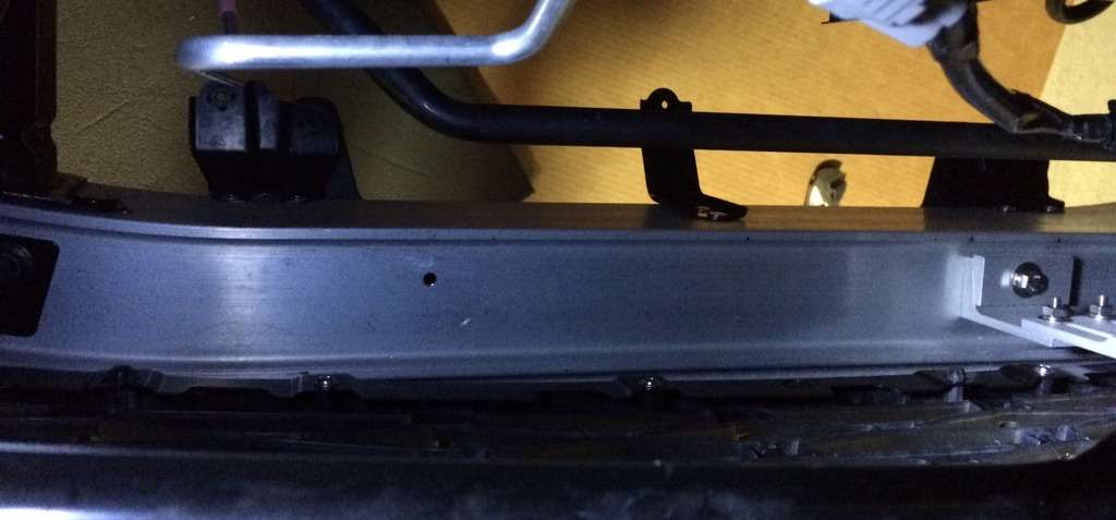
Bumper Drilled and Tapped for Brackets
mpsk.jpg


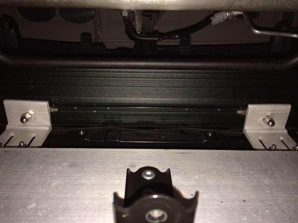
LED Light Bar Mounted
d04d.jpg


LED Light Bar Mounted Underside View
nppt.jpg


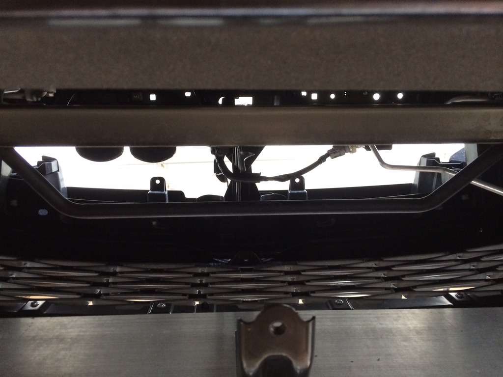
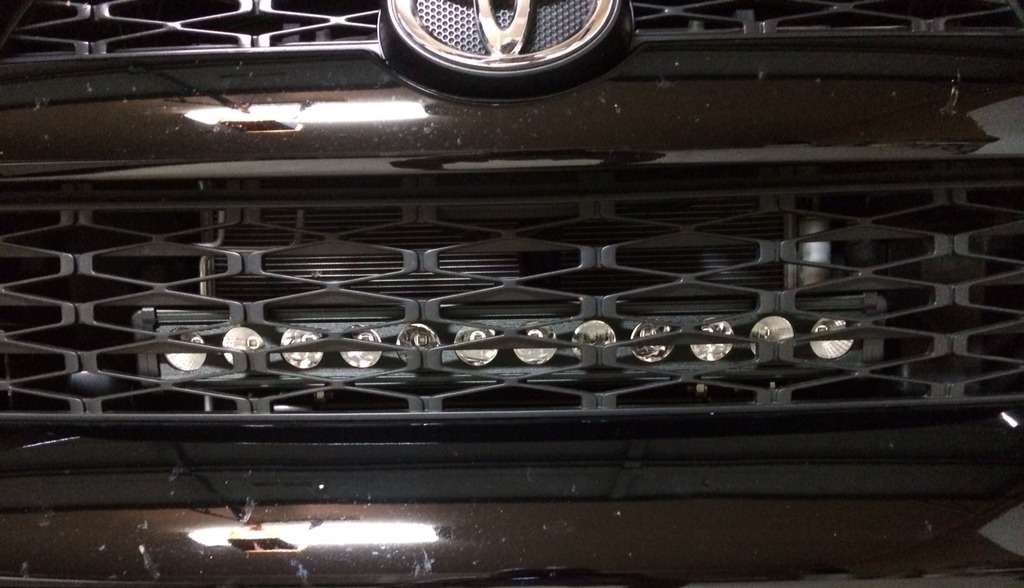
LED Light Bar Mounted Grill View
2ttk.jpg


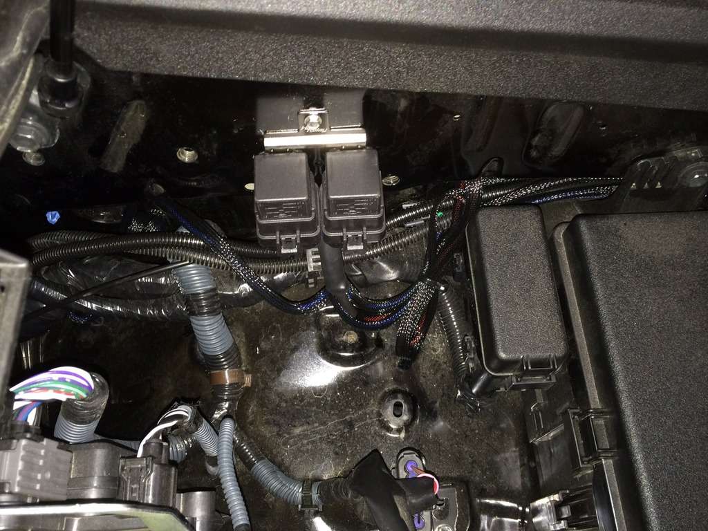
Wiring Harness and Relays Installed
fvcx.jpg


LED Light Bar Trigger Wire Connected to High Beam Wire
gpdu.jpg


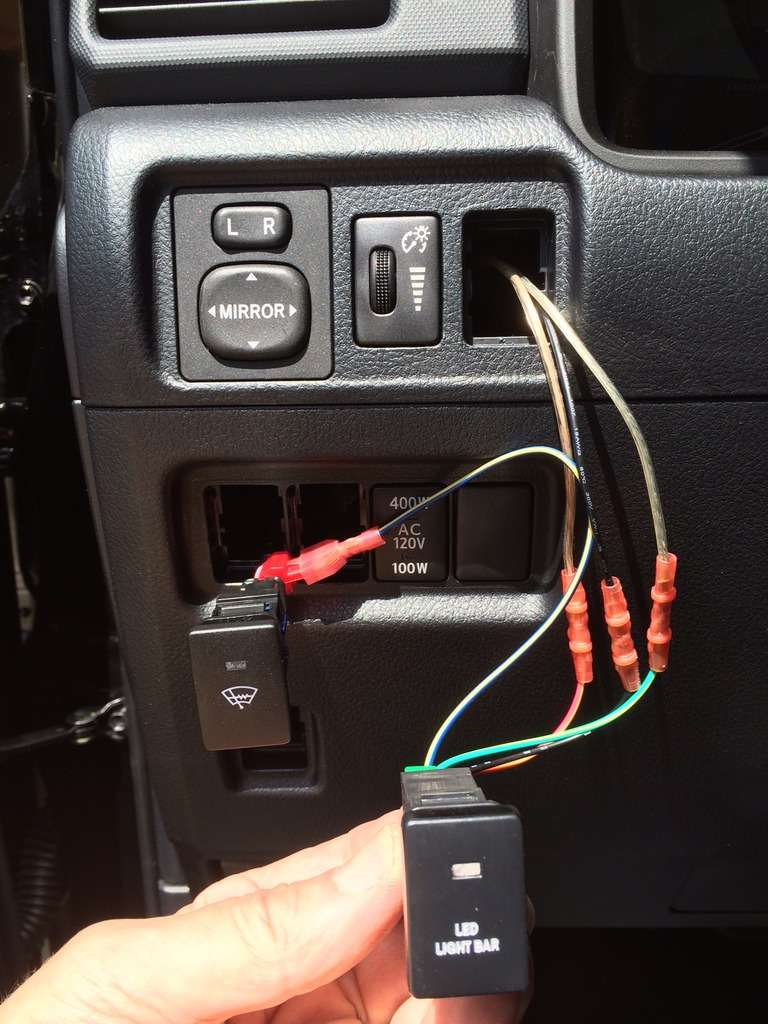
LED Light Bar Switch Wired Up
(Obviously, the blue/white wire will be run thru the switch hole and connected back to the T-tap)
dpja.jpg


LED Light Bar Switch
ixei.jpg


LED Light Bar_1
42ld.jpg


LED Light Bar_2
1l2f.jpg


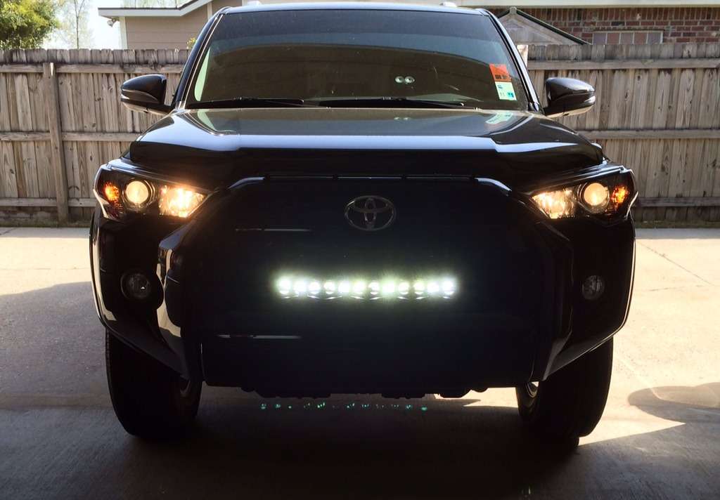
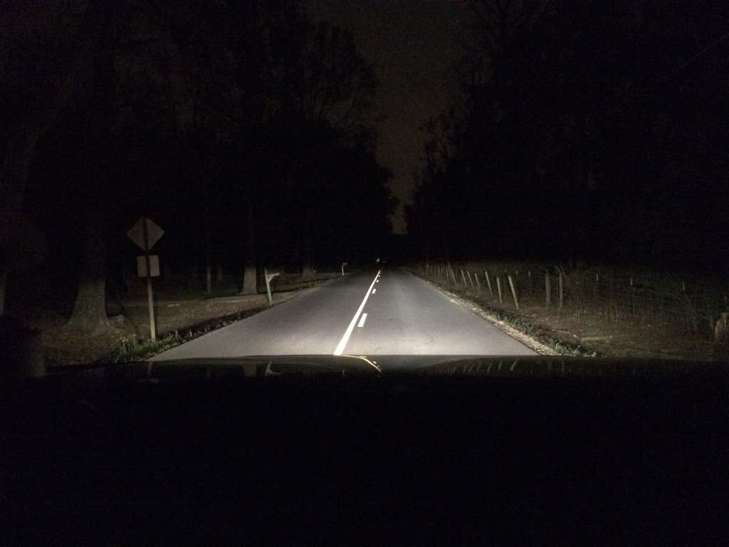
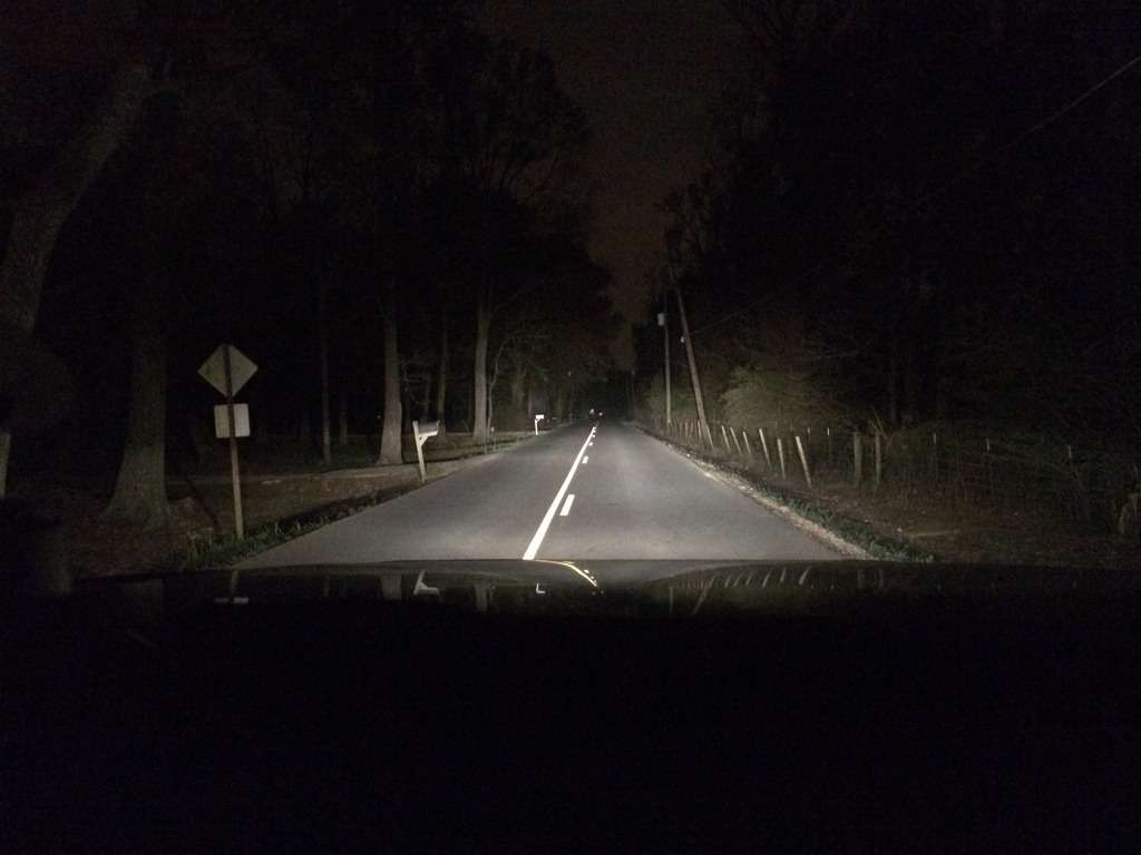
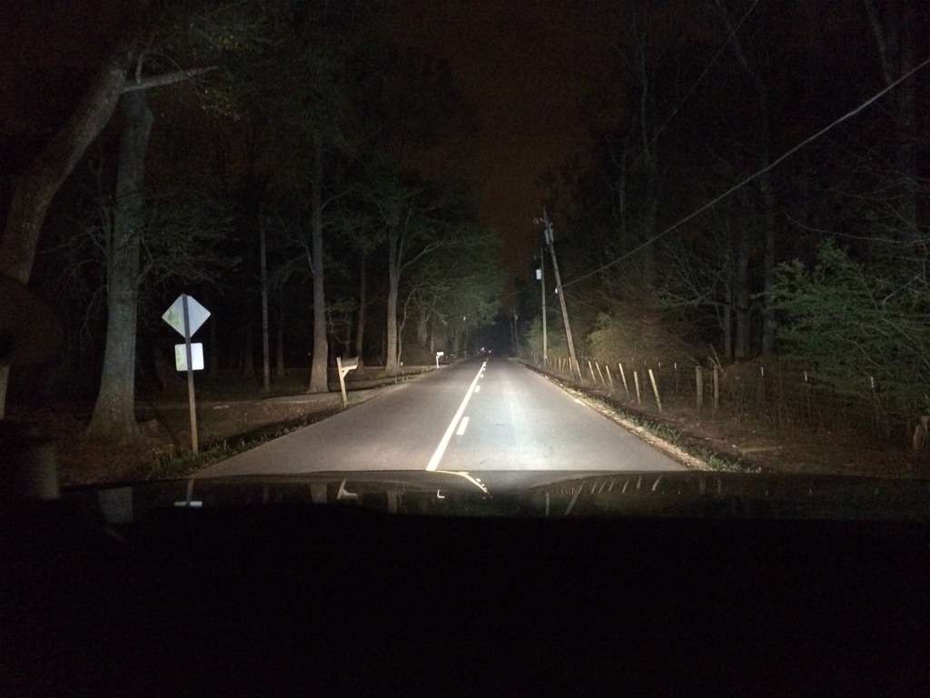
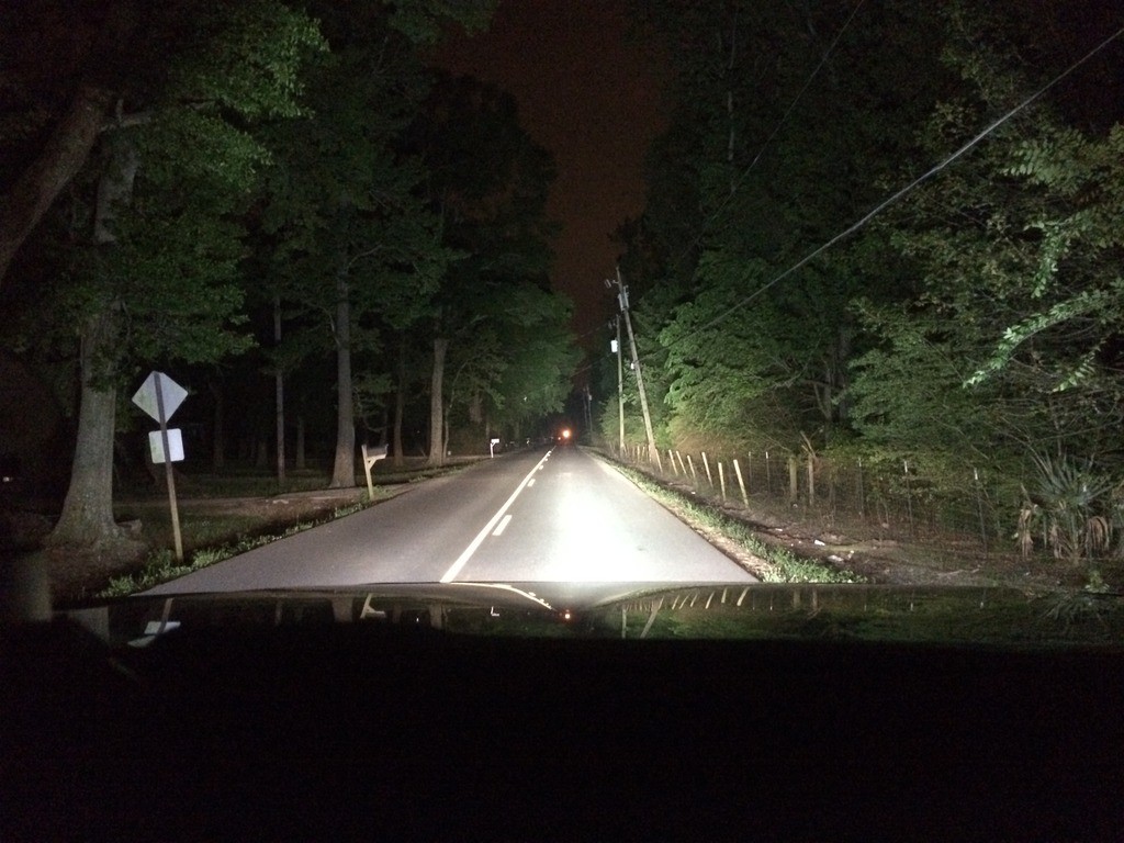
As requested, Light Output Pics Added


Low Beams
m35v.jpg


Low and High Beams
f924.jpg


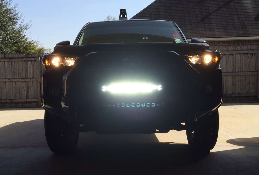
Full Beams with LED Light Bar
(Keep in mind, output is partially blocked by grill, haven't decided whether to cut it or not!)
ym54.jpg


Picture after the grill opened up!
Huge Difference!


maiqp.jpg


Huge thanks to Saker, he answered all my questions and my install was super easy once I had the basic idea of what is going on. I can't recommend using the linking wiring harness, it made things 1000x easier.
 

Attachments

  • IMG_3894.jpg
    IMG_3894.jpg
    126.4 KB · Views: 716
  • thumbnail_IMG_7355.jpg
    thumbnail_IMG_7355.jpg
    131.7 KB · Views: 732
Nice install and you answered my question about drilling into the bumper! We just picked up a 21' ltd and I noticed that the bumper looks like a primo spot for the light bar brackets!!
 
Not sure if this is the right place to post this but I’m struggling to figure out simple wiring for DD SS3 driving lights. I bought a harness with a relay which has three wires going to a switch with 3 positions on it: 1white/2blue/3black. I’m trying to connect these wires to an AOB switch that has red/green/blue/black. I want to use the wiper heater switch wires to provide dash lighting. I also want to wire the lights so they only have power when key is in ACC position. Any tips on what connects to what?
 
Not sure if this is the right place to post this but I’m struggling to figure out simple wiring for DD SS3 driving lights. I bought a harness with a relay which has three wires going to a switch with 3 positions on it: 1white/2blue/3black. I’m trying to connect these wires to an AOB switch that has red/green/blue/black. I want to use the wiper heater switch wires to provide dash lighting. I also want to wire the lights so they only have power when key is in ACC position. Any tips on what connects to what?

I can't help you as I'm not familiar with the harness you have or how its set up.
 

Members online

No members online now.

Forum statistics

Threads
278,316
Messages
3,554,112
Members
248,016
Latest member
Advally Service

Trending content

Back
Top