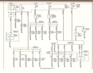
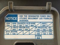
I've got the switch turning the LEDs on/off independent of everything else. It appears as if the wires to the relay are assembled wrong based on the instructions but I got it to work.
Also (and I agree, its more likely me than them), the color coding to function on the switch seems to be off as well. Apparently the switch's black wire controls its internal LED and is not ground (according to the diagram). I identified the parking light circuit but when I plug in switch's black wire something odd happens (I'm sure you guys will know right away what it is). When the parking lights are off, the switch's internal LED is on. When I turn the parking lights on, the switch's internal LED turns off. What gives?
Are you sure you have it connected correctly?
I think you need to understand the 2 pairs of wires in the switch literally have nothing to do with each other... even the instructions tell you that... its actually pretty clear as to how it works.
Based on the instructions:
Two wires on the switch are to switch positive 12v to the control trigger on the relay.
Note: When someone says switch positive, that does not mean that you connect +&-, you connect two +/+. One side of the switch is a supply, the other is the outlet. It really doesn't matter what color goes to what in a single pole switch.
The supply can be connected to literally ANY 12v source in the car. The other end is connected to the relay trigger, which will turn on when it gets + voltage to its terminal.
The other two, Blue&Black, are literally just the +/- connection to make the LED turn on... that's it.
It appears the other problem is you are not using the DMM tool to actually check circuits before connecting thing to car. Perhaps the 4Runner cuts power to that circuit when the parking lights are actually on... thus turning off the LED. Just hook up the meter and check it so you know for sure.
I already mentioned earlier in this thread, if you want the LED to be on, and stay on, connect it to a circuit that supply persistent 12v power when the vehical is keyed on... for example: Cig Lighter & Accessory Power outlet circuits... They even tell you to do this in the switch instructions.
Just so you know, you really dont need to follow the directions these things come with, its only a recommendation, and a generic one based on how they feel people might want to use it. The better your DC electronics fundamentals are, the easier this stuff becomes.
If you did buy a DMM as you mentioned earlier, I think you should use it, because its literally the only thing you need, to make this sort of work foolproof.
You should consider watching this video, and others like it to learn how you can apply a DMM to your projects so you can get it right the first time without 2nd guessing yourself.
Voltage
https://www.youtube.com/watch?v=ZBbgiBU96mM
Switch/Continuity @ Resistance
https://www.youtube.com/watch?v=InJhgwmj2So
All this is meant to be constructive criticism so dont take it any other way... I love the DIY side of this stuff and really just trying to help.