Positivly or negativly charged?

Well, it's a Toyota, so it's going to be metric. Hard to tell from that photo, but probably M5, maybe M6. Either find a bolt that fits and measure it, or thread some taps in there by hand until you find one that fits.

This is the driver side panel btwn the firewall and the engine bay fusebox.
 
This should help.
 

Attachments

  • image.jpg
    image.jpg
    96.4 KB · Views: 172
It's going to be either M8 X 12.5 or M10 X 1.25.

Thx, it turns out to be M8x1.25.

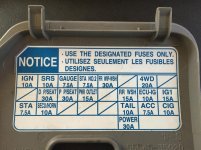
I put it all together last night, but the key for the fuse panel inside the cab is less than helpful. Where is the 12v accessory circuit, as far as I can tell it's not labeled. The open circuits just have lines through that position on the key, what does that mean? I'm guessing it means there isn't a circuit wired to that position. And that takes me back to, where is the 12v accessory circuit? When I hooked it all up, the switch lit up without the keys and no power to the accessories or parking lights. Clicking the switch did not turn the LEDs on, so I don't understand what I'm doing wrong. I connected relay red to switch red, relay black to switch black, relay blue didn't seem to do anything no matter what I hooked it to, and switch blue I plugged into a slot in the fuse panel but that didn't seem to do jack shit either. I contacted Run-D regarding the wiring harness as I cut off the supplied (shitty) switch and got them to confirm what each wire did (I know it's supposed to be standardized but I wanted to check).

Where and how can I tap into the following circuits for the control switch (preferably in the cab fuse box)?

- accessory 12v circuit
- dash light circuit

What I've got to work with now are three wires from the relay: red (positive), black (negative) and blue (control).

On the switch I've got: green (still not sure what to do with it), red (I'm guessing this goes to the red wire from the relay), blue (supposed to connect to the parking lights circuit which I can't identify), black (guessing this mates with the black from the relay although the instructions say to should go to ground).

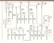
This morning I found this video about the fuse box in an FJ wire switch to an FJ in cab fuse box, are there any maps or videos similar to this one that actualy show the details of the circuits?

Below is the key for my in cab fuse box, what is STA & STA No.2? What's IG1? I can guess most of these, but there's no key I can find to explain all of them.
 

Attachments

  • IMG_8934.jpg
    IMG_8934.jpg
    135.4 KB · Views: 212
Last edited:
I think I just figured out where to plug in the switch blue wire for it's internal LED. Looks like if I plug the fuse tap adapter into the tail circuit it'll light the switch only when I have my parking lights on.

Lets see how this works...
 
Last edited:
I got a DMM and the fuse TAPs will be here today. After searching YouTube I can't find a decent video or explanation on how to run the wires into the cab to connect to the switch. From what I found on T4R it looks like I can:
  1. cut the switch contacts off the wires connecting the switch to the relay
  2. cut off the little nipple on the large firewall grommet and feed the wires through the firewall to the cab
  3. reconnect the switch contacts to the LED wires and connect the LED wires to the switch in the dash
I get the impression this is the cleanest way to wire anything from the engine bay to a switch in the cab, yes? Am I missing anything?

I am likely to add a number of lights in the future: roof light bar, bumper mounted driving lights, side and rear lights. If I knew exactly what I needed to run I'd run all the wires now since I'll be in there but I don't. Is there anything I can do or should do to prepare for this eventuality since I'll be going through from the engine bay to the cab anyway?

To future proof yourself I'd personally wire your accessories straight to the battery and run a dedicated fuse panel (like this 82-2303 - ATO®/ATC® Fuse Panel, (6 Position)) separate from factory wiring. This simplifies your install and makes it easier to add accessories in the future. The more you add the more of a mess you end up making and it ends up looking like a hack job. The cleanest installs and ones with the least problems are done this way.

Just my 2 cents.
 
So...I ****ed up my negative battery cable bolt and I have to replace it. I noticed the standard terminal isn't well suited for connecting anything new. The guy at the auto parts store suggested I replace the terminal, I'd rather not do that. I'm just looking for a longer battery cable bolt that would fit the application allowing me more room to connect ditch lights, light bars, etc...

Thoughts?
 
So...I ****ed up my negative battery cable bolt and I have to replace it. I noticed the standard terminal isn't well suited for connecting anything new. The guy at the auto parts store suggested I replace the terminal, I'd rather not do that. I'm just looking for a longer battery cable bolt that would fit the application allowing me more room to connect ditch lights, light bars, etc...

Thoughts?

Why are you even removing the battery negative terminal post? You could have just used a chassis ground for a low amp application like that... I thought that's what you were going to do with the M8x1.25 bolt?

Regarding the terminal... I really dont know what your terminal looks like... but if its not well suited for accessories, then you should change the terminal. If all it needs is replacement hardware, then the fix should be self explanatory.

In addition to that... having to remove and re-install battery post / terminal connections every time you need to make an electrical change might cause premature wear on those items, possibly leading to poor connectivity and reliability concerns.

You want those connections to be as solid as possible... so choose the best solution to get you there. Even if that is hiring a processional if you feel its not within your capability.

Don't bandage fix or half ass solutions... you will end up paying for them one way more another.

In addition to that, since you seem to be on the path of adding accessories in the future... I would do whatever you have to do to be able to accommodate a fuse block, with a separate bus bar for ground if you dont have one built into the fuse block...

Get someone to install something like this under the hood for you. That way you have a completely separate area to make your electrical connections...

https://www.bluesea.com/products/5025/ST_Blade_Fuse_Block_-_6_Circuits_with_Negative_Bus_and_Cover

5026-cover-nocover-650.jpg
 
Last edited:
Why are you even removing the battery negative terminal post? You could have just used a chassis ground for a low amp application like that... I thought that's what you were going to do with the M8x1.25 bolt?

The LED wiring harness instructions have you connecting to both the positive and negative terminals, I had a bad nut that damaged the end of the bolt. The bolt is still holding the terminal tight on the negative post but if I want to use it to attach anything else the threads are toast. I can replace the terminal bolt easily enough.

I used the M8 bolt to secure/ground the relay, as far as I can tell this is correct.

I'm not sure how soon a roof bar or other accessories are going to be installed, I have other items prioritized (lift, rock sliders, etc). So in the near term all I'm installing are these ditch LEDs and I just wanted to get it done and not overly complicate it at the moment. I do appreciate your advice and didn't know about the fuse block, I think that will be the way I go when the time comes.

Fixing the terminal bolt is not a big deal, thank you for the fuse block info.

Wiring the switch is the issue remaining, I think with what I learned today I can get it sorted.
 
Just a hint... Most of the time there is no electrical ground though that mounting hole in the relay... you could have just zip-tied that entire thing with the rest of the hiring harness loom, it does not need to be mounting using a M8 bolt.

Instead, you should have just screwed one of these things into it... and them made an electrical connection to it using the other M8 screw hole...

https://www.bluesea.com/products/2304/Common_100A_Mini_BusBar_-_5_Gang

Either way... arm yourself with this information so you can improve the install at a later date or if your terminal post needs to be replaced...
 
Back to the switch. I thought I could connect the black switch wire to the black relay wire (negative back to the battery) and call it a day. But, according to their diagram, the switch's black wire has to go to ground. If I do in fact have to do this, where in the cab is a ground point near the fuse box?
 
Back to the switch. I thought I could connect the black switch wire to the black relay wire (negative back to the battery) and call it a day. But, according to their diagram, the switch's black wire has to go to ground. If I do in fact have to do this, where in the cab is a ground point near the fuse box?

You dont have to run it back to the battery, or the relay, but you can...

Just find any chassis ground that is in a convenient location for you. They all go to the same place anyway.

Your DMM tool can help you identify, and verify that you can continuity with the chassis/common/negative.

For non-current handling applications... you can almost use anything you want for a chassis ground point.
 
Last edited:
I've got the switch turning the LEDs on/off independent of everything else. It appears as if the wires to the relay are assembled wrong based on the instructions but I got it to work.

Also (and I agree, its more likely me than them), the color coding to function on the switch seems to be off as well. Apparently the switch's black wire controls its internal LED and is not ground (according to the diagram). I identified the parking light circuit but when I plug in switch's black wire something odd happens (I'm sure you guys will know right away what it is). When the parking lights are off, the switch's internal LED is on. When I turn the parking lights on, the switch's internal LED turns off. What gives?
 
Last edited:
I've got the switch turning the LEDs on/off independent of everything else. It appears as if the wires to the relay are assembled wrong based on the instructions but I got it to work.

Also (and I agree, its more likely me than them), the color coding to function on the switch seems to be off as well. Apparently the switch's black wire controls its internal LED and is not ground (according to the diagram). I identified the parking light circuit but when I plug in switch's black wire something odd happens (I'm sure you guys will know right away what it is). When the parking lights are off, the switch's internal LED is on. When I turn the parking lights on, the switch's internal LED turns off. What gives?

Are you sure you have it connected correctly?

I think you need to understand the 2 pairs of wires in the switch literally have nothing to do with each other... even the instructions tell you that... its actually pretty clear as to how it works.

Based on the instructions:
Two wires on the switch are to switch positive 12v to the control trigger on the relay.

Note: When someone says switch positive, that does not mean that you connect +&-, you connect two +/+. One side of the switch is a supply, the other is the outlet. It really doesn't matter what color goes to what in a single pole switch.

The supply can be connected to literally ANY 12v source in the car. The other end is connected to the relay trigger, which will turn on when it gets + voltage to its terminal.

The other two, Blue&Black, are literally just the +/- connection to make the LED turn on... that's it.

It appears the other problem is you are not using the DMM tool to actually check circuits before connecting thing to car. Perhaps the 4Runner cuts power to that circuit when the parking lights are actually on... thus turning off the LED. Just hook up the meter and check it so you know for sure.

I already mentioned earlier in this thread, if you want the LED to be on, and stay on, connect it to a circuit that supply persistent 12v power when the vehical is keyed on... for example: Cig Lighter & Accessory Power outlet circuits... They even tell you to do this in the switch instructions.

Just so you know, you really dont need to follow the directions these things come with, its only a recommendation, and a generic one based on how they feel people might want to use it. The better your DC electronics fundamentals are, the easier this stuff becomes.

If you did buy a DMM as you mentioned earlier, I think you should use it, because its literally the only thing you need, to make this sort of work foolproof.

You should consider watching this video, and others like it to learn how you can apply a DMM to your projects so you can get it right the first time without 2nd guessing yourself.

Voltage
https://www.youtube.com/watch?v=ZBbgiBU96mM
Switch/Continuity @ Resistance
https://www.youtube.com/watch?v=InJhgwmj2So

All this is meant to be constructive criticism so dont take it any other way... I love the DIY side of this stuff and really just trying to help.

 
Are you sure you have it connected correctly?

Yes, I need to learn how to use the DMM...thx for the video. I'll make time to learn how to use it and test on my next round of getting this thing done.

Last night I tested every fuse position I thought might be powered such that when the parking lights are on, the light in the switch is on. By tested I mean based on how I would expect each fuse slot to function (systems it supports). What I found is that even though there are at least two fuses that (from the description I could find) appear to be associated with the parking lights or dash lights; one cuts off when the parking lights are on...the other is always on. It appears like I'm not going to be able to tie it in to the parking light circuit. If that's the case I'll find a circuit that's tied to the ignition. I tried a bunch of circuits that I expected would be on when the ignition is on and all of them were always on. So, yes the DMM is going to allow me to test (more effectively once I understand how to use it) but I've been trying to test what would work in my own way as well.

Thx.
 
Last edited:
You are too focused on the diagram that stuff came with... aside from identifying what each wire does, that stuff should have found its way into a trash can a long time ago.

Just use CIG or ACC... i've been hint at this since the beginning of this thread.. not sure what you haven't just used that.

I really try and avoid tapping into anything that's "mission critical".

Plus you have plenty of overhead between those two circuits, which are ignition controlled anyways, and really a very safe place to pull from. A fault on those lines dont effect drive-ability in any way shape or form...

In addition to that, if you tap your trigger voltage for the relay from there, you can't accidentally leave your lights on if you forget to turn them off... so that protects you from killing your starter battery if you ever forgot to turn them off. Plus the switch LED is on when the car is on... Simple, elegant, and nothing complicated...
 
Last edited:

Members online

Forum statistics

Threads
278,316
Messages
3,554,110
Members
248,016
Latest member
Advally Service

Trending content

Back
Top