Solved with details: 3rd generation 4Runner digital clock revived (tooth surgery)

Status
Not open for further replies.

mom

Banned
Solved: 3rd generation Toyota 4Runner digital clock repair DIY

SUMMARY: (MY FIRST DIY on this forum! Wish me luck and help me with the naysayers. Gory details to follow in photographs)
1997 Toyota 4-Runner clock has been dead for a decade. Removed center cluster. Removed clock. Opened clock. Removed four tiny silver springs; yanked four contact pins; soldered pins to the circuit board; threw away the old silver springs. Reassembled clock. Reassembled cluster. Voila! The digital ticker is now back in action!

Why another DIY? The main DIY in the first reference was good, but it wasn't exactly the same setup as mine; plus in the reference threads, MANY people had difficulty resoldering the pins, so I took pains to describe those steps better than the main DIY and with more detailed pictures. It's ok if this is too much detail because those who already know how don't need this DIY. But for those, like me, who are scared to move forward before knowing what they're doing, this DIY should help.

REFERENCES: (The intent was to stand on their shoulders and fill in what they left off.)
http://www.toyota-4runner.org/3rd-gen-t4rs/67508-3rd-gen-dash-clock-fix-3.html
http://www.toyota-4runner.org/3rd-gen-t4rs/28758-4runner-clock-problem.html
http://www.toyota-4runner.org/3rd-gen-t4rs/38559-clock.html
http://www.toyota-4runner.org/3rd-gen-t4rs/45709-dashboard-clock-not-working.html
http://www.toyota-4runner.org/accessories/30579-digital-clock.html
http://www.toyota-4runner.org/audio-electronics/6821-1998-4runner-limited-digital-clock.html
http://www.toyota-4runner.org/3rd-gen-t4rs/59184-what-fuse-fixes-clock.html
http://www.toyota-4runner.org/3rd-gen-t4rs/55352-help-clock-problem-my-99-limited.html
etc.

READ THE FACTORY MANUAL:
After reading the references above, open the Toyota 4Runner 1997 factory shop manual to sections BO-45 “Remove Center Cluster Finish Panel”, AC-55 “Air Conditioning Control Assembly”, & BE-157 “Clock Troubleshooting” in the Toyota 4Runner shop manual (Note: The Chilton repair manual was virtually useless for this particular repair.)

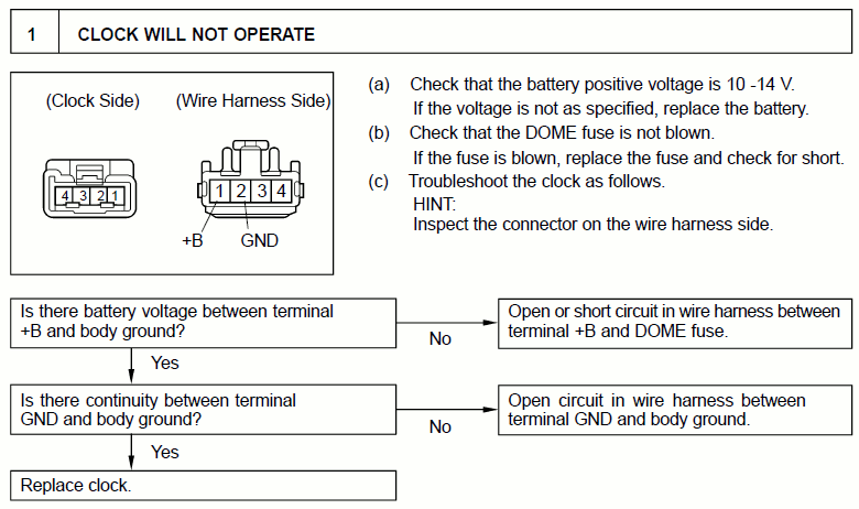
Notice the factory shop manual advises to check the dome-light fuse if the digital clock is not working. This DIY assumes your dome light fuse tested OK.

33175d1284979980-how-do-you-post-text-interspersed-pictures-diy-what-am-i-doing-wrong-4runner_clock_fix_01.jpg


Remove the key from the ignition so as not to short anything.
Notice my Toyota 4Runner has the clock in the top-left corner of the A/C panel.
33174d1284979966-how-do-you-post-text-interspersed-pictures-diy-what-am-i-doing-wrong-4runner_clock_fix_00.jpg


Remove the four knobs on the heating and air conditioning controls in the center cluster by pulling straight out. There is no need to remove the radio volume control knob or the air-conditioning on/off switch (ask me how I know).
33176d1284979989-how-do-you-post-text-interspersed-pictures-diy-what-am-i-doing-wrong-4runner_clock_fix_02.jpg


Once the four knobs are off, your 4Runner center cluster will look like this.
33177d1284979997-how-do-you-post-text-interspersed-pictures-diy-what-am-i-doing-wrong-4runner_clock_fix_03.jpg


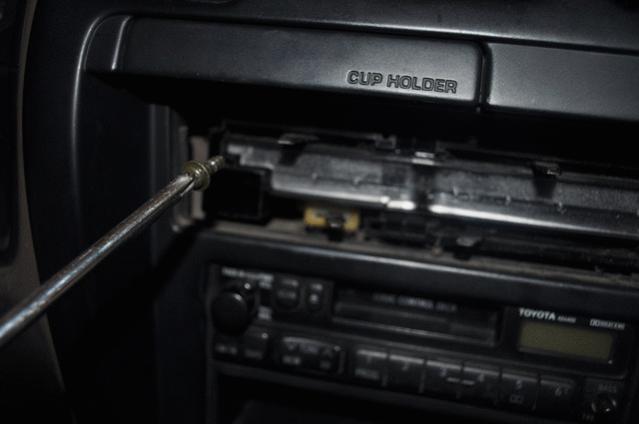
With a thin spatula (the factory manual recommends a flat-blade screwdriver taped on the end to protect the plastic), carefully pry off the heating and air conditioning cover plate.
33178d1284980008-how-do-you-post-text-interspersed-pictures-diy-what-am-i-doing-wrong-4runner_clock_fix_04.jpg


Notice the air-conditioning on/off button will pop out along with the heating and air conditioning cover plate as you work the tool around the edges.
33179d1284980016-how-do-you-post-text-interspersed-pictures-diy-what-am-i-doing-wrong-4runner_clock_fix_05.jpg


Remove the heating and air conditioning cover plate with the air-conditioning on/off switch attached.
33180d1284980026-how-do-you-post-text-interspersed-pictures-diy-what-am-i-doing-wrong-4runner_clock_fix_06.jpg


Page BO-45 of the 1997 Toyota factory shop manual shows the location of the two #2 Phillips head screws which need to be removed.
33181d1284980037-how-do-you-post-text-interspersed-pictures-diy-what-am-i-doing-wrong-4runner_clock_fix_07.jpg


Remove the bottom right #2 Phillips head screw from the center cluster.
33182d1284980149-how-do-you-post-text-interspersed-pictures-diy-what-am-i-doing-wrong-4runner_clock_fix_08.jpg


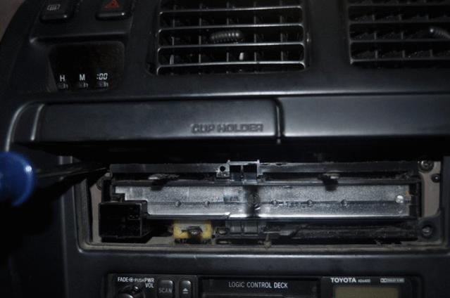
I started to remove the upper left #2 Phillips screw from the center cluster when I realized if it fell, it would be lost forever.
33183d1284980158-how-do-you-post-text-interspersed-pictures-diy-what-am-i-doing-wrong-4runner_clock_fix_09.jpg

< arbitrarily cut here because of overly restrictive forum posting rules >
 
Last edited:
Register to hide this ad
(continued)

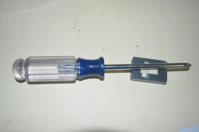
I magnetized the #2 Phillips head screwdriver with an uncoated neodymium magnet.
33184d1284980166-how-do-you-post-text-interspersed-pictures-diy-what-am-i-doing-wrong-4runner_clock_fix_10.jpg


With the newly magnetized screwdriver, I was able to remove the deeper top-left #2 Phillips screw without having it fall down into the bowels of the dashboard.
33185d1284980175-how-do-you-post-text-interspersed-pictures-diy-what-am-i-doing-wrong-4runner_clock_fix_11.jpg


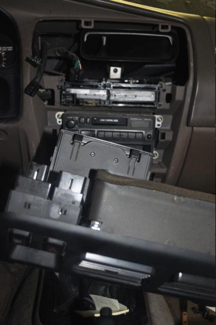
Nothing else is screwed into place holding the center cluster to the dashboard. With your bare hands, work your way around the edges pulling the center cluster outward. It will be stuck at the very bottom with its lip tucked under plastic panels. These can remain (or you can pull the bottom plastic panels outward slightly if it helps remove the center cluster).
33186d1284980183-how-do-you-post-text-interspersed-pictures-diy-what-am-i-doing-wrong-4runner_clock_fix_12.jpg


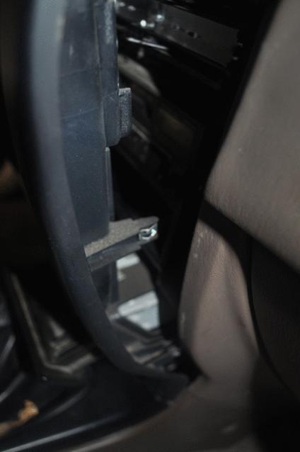
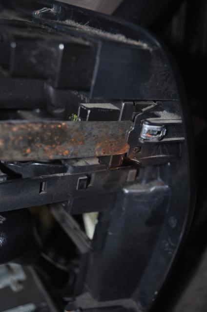
This is what the clips look like at the sides of the center cluster.
33187d1284980194-how-do-you-post-text-interspersed-pictures-diy-what-am-i-doing-wrong-4runner_clock_fix_13.jpg


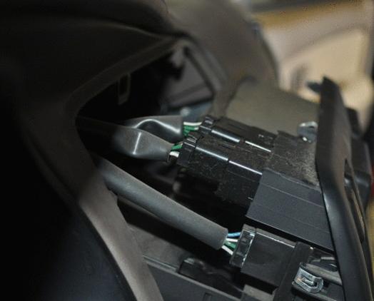
At the top-left of the back of the center cluster, you will see three wiring harness connectors (one for the defroster, another for the hazard lights, and a third for the digital clock).
33188d1284980200-how-do-you-post-text-interspersed-pictures-diy-what-am-i-doing-wrong-4runner_clock_fix_14.jpg


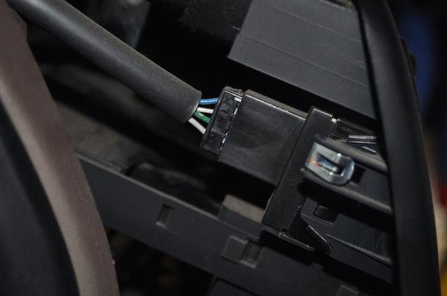
Press on the tabs and pull forward (toward the engine) to remove the hazard-light and defroster switch harness connectors in order to gain greater access to the digital clock harness connector.
33189d1284980209-how-do-you-post-text-interspersed-pictures-diy-what-am-i-doing-wrong-4runner_clock_fix_15.jpg


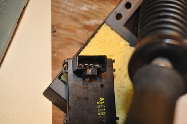
Pull the four-pin digital-clock wiring harness away from the back of the digital clock.
33190d1284980262-how-do-you-post-text-interspersed-pictures-diy-what-am-i-doing-wrong-4runner_clock_fix_16.jpg


With a voltmeter, measure the voltage from pin #1 of the digital clock harness connector and any convenient ground (I used the metal of the ignition switch as my ground).
33191d1284980269-how-do-you-post-text-interspersed-pictures-diy-what-am-i-doing-wrong-4runner_clock_fix_17.gif


In my situation, battery voltage was observed as one would expect from a working digital clock. The Toyota factory shop manual says if the voltage is good, the clock is bad. They say to buy a new $300 clock, but we have a better idea! :)
33192d1284980283-how-do-you-post-text-interspersed-pictures-diy-what-am-i-doing-wrong-4runner_clock_fix_18.gif


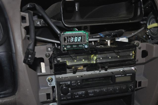
To remove the digital clock, you need to pull the top of the center cluster out as far as you need to get your grubby little hands in there. You do not need to remove any other wiring harness connector (there are a couple still attached at the bottom of the center panel).
33193d1284980295-how-do-you-post-text-interspersed-pictures-diy-what-am-i-doing-wrong-4runner_clock_fix_19.jpg


< arbitrarily cut here due to overly restrictive forum posting rules >
 
(continued) Using your wide-blade spatula, GENTLY pry the four tabs off the back of the digital clock body. Be VERY CAREFUL as these tabs are known to break (I damaged one of mine, others lost a couple).
33194d1284980306-how-do-you-post-text-interspersed-pictures-diy-what-am-i-doing-wrong-4runner_clock_fix_20.jpg


When the grip of these four tabs has been loosened, the digital clock will pop out of the center cluster into your hands. It's now time to head over to your shop bench.
33195d1284980315-how-do-you-post-text-interspersed-pictures-diy-what-am-i-doing-wrong-4runner_clock_fix_21.jpg


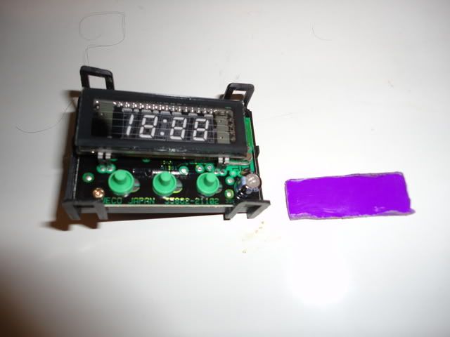
Pulling four more tabs outward, you can separate the smoky clock face from the digital clock body.
33196d1284980328-how-do-you-post-text-interspersed-pictures-diy-what-am-i-doing-wrong-4runner_clock_fix_22.jpg


The DIYs say that the three adjusting buttons will stay with the clock face, but, in my case, the buttons stayed on the clock itself.
33197d1284980338-how-do-you-post-text-interspersed-pictures-diy-what-am-i-doing-wrong-4runner_clock_fix_23.jpg


Then they fell off, one by one as there is NOTHING holding them on once the smoky front of the clock is removed. I thought I was hosed but it turned out to be a non event.
33198d1284980537-how-do-you-post-text-interspersed-pictures-diy-what-am-i-doing-wrong-4runner_clock_fix_24.jpg


Soon all three contact buttons were off. This turns out to be "no big deal" TM
33199d1284980550-how-do-you-post-text-interspersed-pictures-diy-what-am-i-doing-wrong-4runner_clock_fix_25.jpg


Magnetize a #0 Phillips screwdriver and remove the two screws holding the circuit board to the digital clock elements.
33200d1284980561-how-do-you-post-text-interspersed-pictures-diy-what-am-i-doing-wrong-4runner_clock_fix_26.jpg


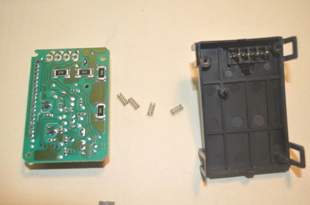
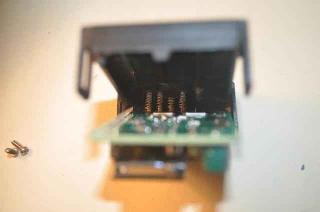
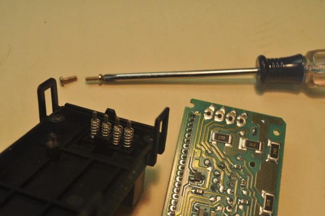
WAKE UP! This step is important! It's the big Kahuna. Slowly separate the clock elements from the circuit board. NOTICE these four tabs and the four silver springs on those tabs. THIS IS THE CULPRIT!
33201d1284980578-how-do-you-post-text-interspersed-pictures-diy-what-am-i-doing-wrong-4runner_clock_fix_27.jpg


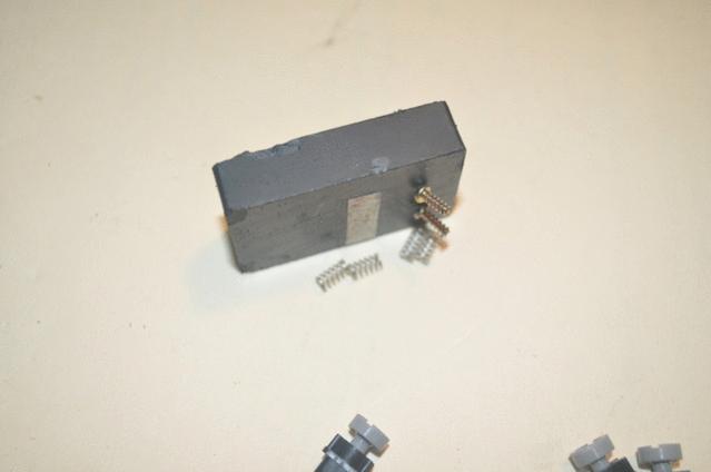
Remove the four silver springs. They are the problem! They are supposed to make good electrical contact (that's why they are silver). Over time, they don't make good contact (that's why banging the clock sometimes works ... just like with the old tube-type TVs).
33203d1284980622-how-do-you-post-text-interspersed-pictures-diy-what-am-i-doing-wrong-4runner_clock_fix_29.jpg


BTW, some wondered if the strong springs were silver plated steel but they are NOT magnetic. Mine were in excellent shape, with plenty of spring tension and no visible corrosion.
33204d1284980630-how-do-you-post-text-interspersed-pictures-diy-what-am-i-doing-wrong-4runner_clock_fix_30.jpg


< arbitrarily cut here due to overly restrictive forum posting rules >
 
(continued)


Here is the key alignment task. Temporarily reattach the circuit board to the digital clock elements. Notice how the four pins align with the circuit board. This is your goal.
33205d1284980643-how-do-you-post-text-interspersed-pictures-diy-what-am-i-doing-wrong-4runner_clock_fix_31.jpg


Some people have reported that simply de-assembling and re-assembling the digital clock (with the four springs) has worked for them, so I tried that (without soldering anything).
33206d1284980887-how-do-you-post-text-interspersed-pictures-diy-what-am-i-doing-wrong-4runner_clock_fix_32.jpg


When reassembled, and plugged into the digital clock wiring harness, the digital clock worked! But, it was intermittent. And often dim. The connection with the springs and the tabs in situ was just flaky. Bad design.
33207d1284980973-how-do-you-post-text-interspersed-pictures-diy-what-am-i-doing-wrong-4runner_clock_fix_33.jpg


Notice you don't need to reassemble the entire digital clock body to test it out; you just need enough to plug it back into the wiring harness.
33208d1284981040-how-do-you-post-text-interspersed-pictures-diy-what-am-i-doing-wrong-4runner_clock_fix_34.jpg


At first I thought I had fixed the digital clock, simply by de-assembling and re-assembling it, as shown by this picture where it was working for a full minute! :)
33209d1284981060-how-do-you-post-text-interspersed-pictures-diy-what-am-i-doing-wrong-4runner_clock_fix_35.jpg


But, a minute later, the lights grew dim and the clock went out like a candle in a slight breeze.
33210d1284981078-how-do-you-post-text-interspersed-pictures-diy-what-am-i-doing-wrong-4runner_clock_fix_36.jpg


So it was back to the shop bench to remove the four tiny problematic silver springs and do the full four-pin solder salute as described in the canonical DIY in reference #1 above.
33211d1284981089-how-do-you-post-text-interspersed-pictures-diy-what-am-i-doing-wrong-4runner_clock_fix_37.jpg


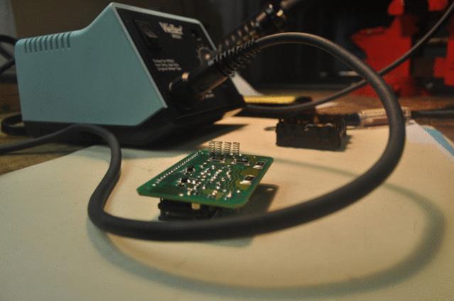
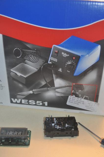
Since I never soldered before, I didn't have any soldering tools. At Fryes, in the Silicon Valley, I found a $100 soldering station that worked perfectly. Many people reported solder problems in the references. I didn't have any problems with this brand new tool. The pins were soldered in just a few seconds at a mid-heat setting.
33212d1284981101-how-do-you-post-text-interspersed-pictures-diy-what-am-i-doing-wrong-4runner_clock_fix_38.jpg


BTW, I didn't really want to pull the pins (like pulling teeth) from the harness connector, so, I briefly contemplated soldering just the silver springs to the circuit board ... but after lining them up time and time again as they fell off the circuit board, I soon tired of that exercise in futility.
33213d1284981940-how-do-you-post-text-interspersed-pictures-diy-what-am-i-doing-wrong-4runner_clock_fix_39.jpg


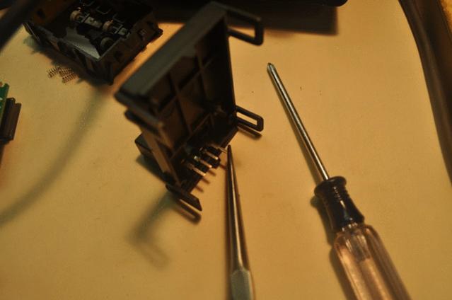
Pensively, with needle-nose pliers, I removed the first "tooth"; it pulled out of the harness connector much easier than I had expected sans damage.
33214d1284989312-how-do-you-post-text-interspersed-pictures-diy-what-am-i-doing-wrong-4runner_clock_fix_40.jpg


< arbitrarily cut and laboriously pasted due to overly restrictive forum posting rules >
 
(continued)

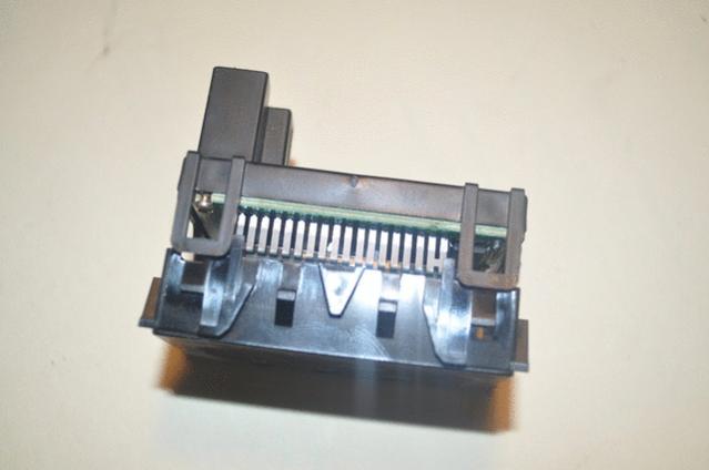
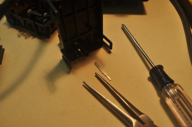
Here's what the pin looks like once it's removed from the harness connector.
33215d1284989324-how-do-you-post-text-interspersed-pictures-diy-what-am-i-doing-wrong-4runner_clock_fix_41.jpg


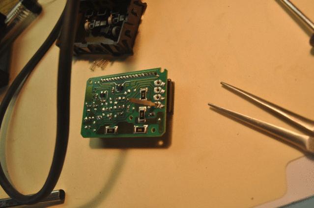
Proudly, I stuck the pin into the hole in the circuit board like a feather in a kid's cap.
33216d1284989334-how-do-you-post-text-interspersed-pictures-diy-what-am-i-doing-wrong-4runner_clock_fix_42.jpg


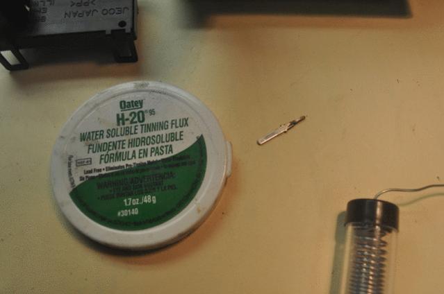
Dipping the pin in flux (that's what the guy at Fryes said to use) might have helped as the solder flowed onto the pin and circuit board in just a handful of seconds as I heated the pin (not the solder).
33217d1284989345-how-do-you-post-text-interspersed-pictures-diy-what-am-i-doing-wrong-4runner_clock_fix_43.jpg


Make sure you align the pins in the SAME ORIENTATION as they were originally! Here you see the second pin standing at attention next to the first.
33218d1284989356-how-do-you-post-text-interspersed-pictures-diy-what-am-i-doing-wrong-4runner_clock_fix_44.jpg


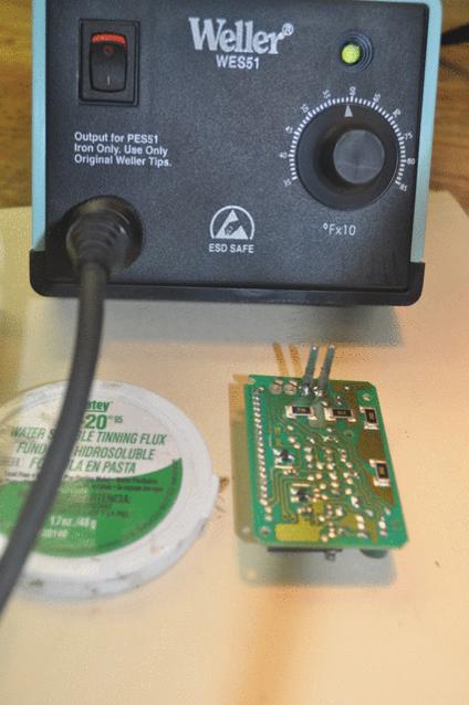
Repeat the tooth-pulling process and the pin-fluxing and alignment and then quick soldering procedure for each pin in turn. Here you see the third pin at attention in a three-fingered salute.
33219d1284989371-how-do-you-post-text-interspersed-pictures-diy-what-am-i-doing-wrong-4runner_clock_fix_45.jpg


Bear in mind that MANY PEOPLE had problems aligning these pins; so I took it to heart the suggestion to LIGHTLY solder the pins first, and then adjust them later.

Interestingly, I got vastly better at this with each successive pin, so, I show only the last (best) pin in detail for you by way of example.

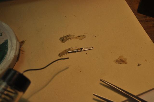
Here you see the last "tooth" ready to be pulled out of the back of the digital clock body.
33220d1284989382-how-do-you-post-text-interspersed-pictures-diy-what-am-i-doing-wrong-4runner_clock_fix_46.jpg


Here you see the pin, after being dipped in the flux, with a bit of solder flowed onto each side (takes only a second or three with the soldering iron set at medium heat).
33221d1284989391-how-do-you-post-text-interspersed-pictures-diy-what-am-i-doing-wrong-4runner_clock_fix_47.jpg


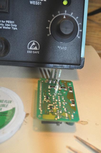
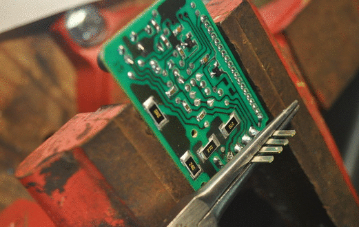
Listen up. Here's another important step! People failed who did not perform this next step adequately! When all four teeth were lightly attached, I heated them up all at the same time, and "aligned" them with a pair of pliers as "teeth braces". I think this was a critical step in the success of the operation overall.
33222d1284989512-how-do-you-post-text-interspersed-pictures-diy-what-am-i-doing-wrong-4runner_clock_fix_48.gif


Here you see the four teeth after the solder has cooled down. Notice the setting on the Weller soldering station. YMMV.
33223d1284989521-how-do-you-post-text-interspersed-pictures-diy-what-am-i-doing-wrong-4runner_clock_fix_49.jpg


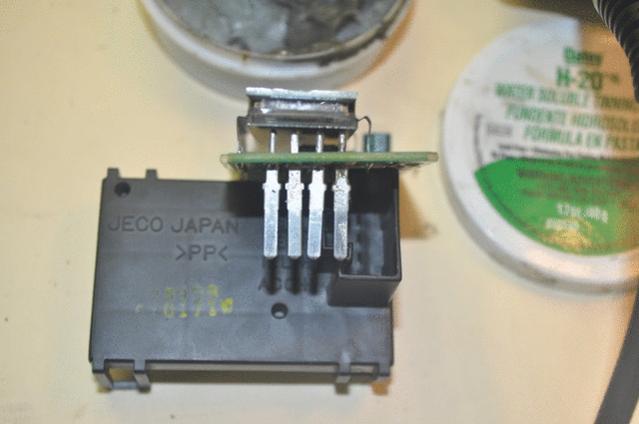
Since it's important that the four teeth are lined up, inspect the four teeth for straightness from every angle. Here you view the biting angle from the top of the incisors. Not perfect. But, as it turns out, plenty good enough to get a date a the prom.

BTW, now is as good a time as ever to inspect ALL solder points on the circuit board. It has been reported that cracks appear next to the tiny flat resistors soldered to the board. I didn't see any cracks and so I left everything else alone. The ONLY thing I touched were the springs (removed) and the pins (soldered).
33224d1284989532-how-do-you-post-text-interspersed-pictures-diy-what-am-i-doing-wrong-4runner_clock_fix_50.jpg


< arbitrarily cut in order to post this DIY successfully after the umpteenth try over a span of two days! >
 
(continued) ...

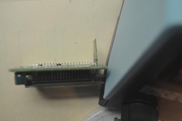
Here you see the pins checked for alignment from the side.
33225d1284989541-how-do-you-post-text-interspersed-pictures-diy-what-am-i-doing-wrong-4runner_clock_fix_51.jpg


Here you see the head-on view of the pretty little soldiers. They are not even close to perfect; but, as it turns out, plenty good enough.
Note:
Don't use plumbing flux or solder for electrical soldering; use rosin core flux!
33226d1284989553-how-do-you-post-text-interspersed-pictures-diy-what-am-i-doing-wrong-4runner_clock_fix_52.jpg


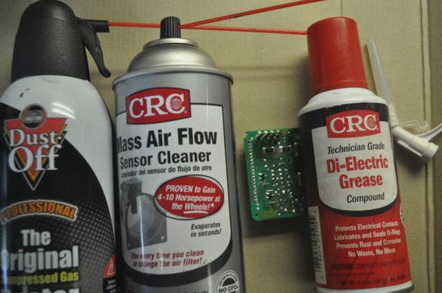
At this point, I suddenly realized if "corrosion" was the initial problem, then leaving (acid?) flux on the metal contacts was probably not a good idea. So I dug around the garage and pulled out a tube of electrical cleaner (CRC non-chlorinated California-safe MAF cleaner was all I had), a tube of compressed air, and a tube of di-electric grease about a decade old.
33227d1284989562-how-do-you-post-text-interspersed-pictures-diy-what-am-i-doing-wrong-4runner_clock_fix_53.jpg


First the contact cleaner, then the compressed air, and lastly the di-electric grease went on. At this point, I realized the goop was all over and it was then that I realized I had no idea of this di-electric grease was a conductor or an insulator! (duh. I didn't think of that until now.)

So, I cleaned it up a bit with the MAF cleaner and compressed air, leaving only a thin (non-shorting?) film on the metal but not glommed up and oozing between the posts like a bad case of gingivitis of the gums.
33228d1284989574-how-do-you-post-text-interspersed-pictures-diy-what-am-i-doing-wrong-4runner_clock_fix_54.gif


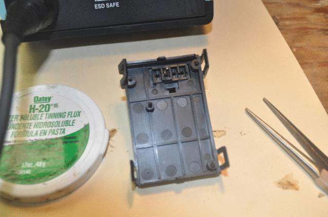
At this point, you're almost home free. Remember, this step NOW is the one most people had problems with as their pins did not fit BACK into the back of the clock body. For me, it was anti-climactic, as the pins slid in like they were buttered (dunno if the di-electric grease helped there).
33229d1284989588-how-do-you-post-text-interspersed-pictures-diy-what-am-i-doing-wrong-4runner_clock_fix_55.jpg


Repeat the steps of screwing the two tiny #0 Phillips head screws in, lining up the three adjusting knobs, and snapping the clock faceplate and back body into place.

Here's where I noticed I damaged one of the "ears" in the clock body, at some point, from all the assembly and disassembly.

Be careful with those ears. They are VERY fragile. Many people reported breaking one or more. Luckily, they are not electrically responsible; so, the clock will still work even if you have to tape the body back on now that the connections are securely clamped in solder!

Here you see the new repair has lasted a full minute!
33230d1284989757-how-do-you-post-text-interspersed-pictures-diy-what-am-i-doing-wrong-4runner_clock_fix_56.jpg


The moment of truth ... the smoke test has lasted a full two minutes! (exactly twice as long as the previous 're-assemble fix'). :)
33231d1284989800-how-do-you-post-text-interspersed-pictures-diy-what-am-i-doing-wrong-4runner_clock_fix_57.jpg


Putting the center console back together was sans drama and was, as they say, the reverse of disassembly, so I think I'll close with the fact that the time was easily adjusted, and, well, two days later, it's still working!

33232d1284989853-how-do-you-post-text-interspersed-pictures-diy-what-am-i-doing-wrong-4runner_clock_fix_58.jpg


Thank you everyone, and especially to
CO_FlyFisher for explaining the critical fact that the PROBLEM is the silver springs make lousy contacts. The SOLUTION is to simply solder the four pins in place on the circuit board (probably only two of which are the problematic power and ground pins ... I wonder what the other two pins are for?).

Note to readers:
Please improve this digital-clock repair DIY by pointing out any errors or omissions so that others can follow easily in our footsteps. Also note that there exist folks on the web who will repair this for about $30. Considering the digital clock repair took me about three hours elapsed time, start to finish (but the picture taking cost me some time), sending your clock out for repair might be a better avenue than fixing it yourself - you won't experience first hand the "voila!" euphoria - but web-repair is yet another way to have a working Toyota 4Runner 3rd-generation digital clock in your center cluster! Thank you for reading this DIY, my first on this forum. :)
 
Last edited:
Very nice writeup. Good job on the soldering for the first time. You made a good choice in getting a real soldering station, not some junky cheap one. I used junky ones for years, and they don't last long, and don't do a good job. We use the Weller's at work and they are great. You would be surprised how nice a solder joint can look but not actually be well connected. Having the proper heat and tip is huge.

BTW, you can get rosin core solder that doesn't require flux. The solder is hollow and the center is filled with rosin flux. The stuff is really easy to use and is cleaner than using plumbing flux. That being said, it is good to have some flux on hand in case the rosin core doesn't do it. I wish we had fry's where I live.
 
outstanding details-we love the way you think! pics and more pics!

You wouldn't happen to be RitzyRunner's MOM wouldya? He is well known on YOTA TECH for write ups this good.:naughty:

:nicethread:
 
Holy Moly!!! :wow: WOW!!! :bravo:

I bet now you realize why most write-ups don't have so many pictures though, huh? ;):

Great job! I'm glad to hear you learned something along the way, and that your clock is now working again. That's what this community is all about! Mine has been flawless since I worked on it back in late May.

One thing though - You should have sent me a PM when you started this project; I could have helped you!!! As of last week, I had spent all but 2 weeks since the beginning of June working out at NASA Ames... :bash: Oh well. (I actually did the write-up from my hotel in Sunnyvale).

Again, great job!!!

PS - Hey Ron, Down Boy! :D
 
Last edited:
What is REALLY interesting is that toyota used BLUE LED lights...
Time to rig up some clear plexyglass and bring that color back out :D
 
I bet now you realize why most write-ups don't have so many pictures though, huh?

Yeah. :( It's really hard to post more than just a few pictures. It took LONGER to post the DIY than it took to do the DIY! I even got banned 'till the end of the month for posting that it was hard to post a long detailed DIY. They called it "whining" in that small-print paragraph in the last section of the last post of the DIY ; I called it "being upfront". Oh well. :)

Anyway, they kindly listened to me when I argued that I was telling the truth - and they lifted the ban immediately. Otherwise I wouldn't be posting right now.

working out at NASA Ames ...I actually did the write-up from my hotel in Sunnyvale).

Wow. You were practically right next door. (I love watching those slow lumbering big planes fly by on their way to Moffett Field. They're LOUD, slow, and HUGE so you can't miss them flying overhead.)

I certainly could have used your help because I still don't know if I did a bad thing by putting the wrong flux on the circuit board (I used pipe flux). And I still don't know if the di-electric grease is a conductor or an insulator ... so if anyone reads this - don't do what I did unless someone confirms those two steps are OK.

Speaking of following a DIY, if it wasn't for YOUR canonical DIY, I would never have known that the springs were the culprit - nor would I have thought to REMOVE the springs - nor that I could easily pull the pins - nor that the solution was to solder those pins directly to the Toyota 4Runner digital clock circuit board.

Thank YOU for your wonderful and canonical 4Runner digital clock fix DIY!!!!!!
 
Di-electric grease is an insulator. Otherwise it would tend to cause shorts between neighboring connections. It's purpose is to keep air and moisture away from the metal that is not in direct contact with the other connector. It thereby inhibits corrosion without impeding current flow or allowing shorts to adjacent circuits.

If you want a conducting grease, Vaseline (petroleum jelly) works fine. Many use it on battery terminals where there is no risk of shorting. But di-electric grease does not interfere with the metal-to-metal connections if used this way. The labels on di-electric grease usually say 'for use on battery terminals'.
 
For those not handy/comfortable with solding

My solding iron isn't narrow tipped and I thought I might do more harm than good. I simply took clock out and apart as described above, then took a pencil eraser to the places where the silver springs contact on the circuit board. Then I took each pin out of the plastic housing and cleaned them all over with the eraser. Next I cleaned off the ends of the springs and stretched the springs just slightly. Reassembled and voila! Clock working as the factory intended.

Took about 20 minutes start to finish and no need for the nice solding iron you have. My repair won't last as long as yours probably will, BUT...it will work and is easy to fix again when it recurres in 3-5 years. I have tried solding my Benz cruise control boards in the past and without the right solding iron at times I cured them, at times I made them worse. Soldering is not my strong suit.
 
Last edited:
Thanks...

I had to register to thank you :bravo:
I do not have any skill in soldering but I had nothing to lose.
With your post I tried to repair the clock which never worked on my 98 LTD and had the surprise to complete it within an hour and its back to life!

Thanks and respects :)

Gil
 
You are awesome!

I just fixed my clock on my 99 and it made my freakin day! It only took 30 minutes thanks to your impeccable instructions! This community is amazing. Keep spreading the knowledge.

Mike:trophy:
 
Status
Not open for further replies.

Members online

Forum statistics

Threads
278,309
Messages
3,554,075
Members
248,016
Latest member
Advally Service

Trending content

Back
Top