Trans Cooler Mount: Need Kansas 5th Gens for New Product Fitment

It's about 3.5" between the condenser and the front edge of the upper rail.

I ordered a bracket and can give you a better idea once it arrives

Thank you.

I'm guessing you didn't see all of the pictures I posted? Scroll back to message #41 and up and they may answer a number of questions.

The FJ's engine radiator mounting is different as are the openings available for hose routing. The best routing on the 4R is on the passenger side as the steel lines from the trans run along the passenger side.

In my install I ran both of the cooler's hoses together but in hindsight I could have run them differently and shortened them a bit. As I recall, one could have home-runned to the steel trans line and the other could have attached to the short steel line coming up from the radiator that you mentioned. The second short steel line can be capped off and abandoned in place. When I get the energy I'll go back and do all that.

The problem with the ideal routing is that it was near impossible to get my hand and a tool in there to remove the factory line clamp. I think a lot of other things will have to be unbolted to create access.

I don't think there is enough room to mount the cooler on the other side of the bracket but I suppose you can try and let us know. I think it might require an entirely new bracket to gain probably very little in terms of air flow coupling if there is such a term. Probably need a engine-mechanical engineer to weigh in.

As an aside, buy some replacement plastic fasteners for the top radiator cover. Some of the Amazon offerings are so brittle they break easily. I bought these and although they look different from OEM they seem to hold well and don't easily break.

https://www.amazon.com/dp/B0B6HGJ2TY?psc=1&ref=ppx_yo2ov_dt_b_product_details

I saw your pictures, but I wasn't able to tell exactly how you tied into the system. I could tell that you ran your hoses to the passenger side of the radiator, but I was unsure how you tied into the system. Your post #43 made it look like you might have tied into the system the same way as the FJ Cruise.

Not sure if the following is clear, but my thought was to remove the current transmission cooler hose from the steel transmission cooler line near the top of the radiator. Then run a new hose from the steel transmission cooler line to the external transmission cooler, using top hole. Next, take the transmission cooler hose that runs to the transmission (that is no longer attached) and reroute it through the bottom hole with the A/C steel line. Finally, use a barbed hose union to add a length of hose so that I can connect to the cold side of the transmission cooler (if needed) and route the fluid to the transmission.
 
Looking forward to the pictures!

If the cooler is moved behind the bracket the lower inlet tube and attached hose will have to contend with the radiator mount being squarely in the way. I think the bracket would be mounted first then try to get the cooler in there to rotate into different positions for fitment check. The bracket that you now have is the result of three different designs iterations.

410223d1708015305-trans-cooler-mount-need-kansas-5th-gens-new-product-fitment-img_8310-1-jpg

Your picture of this is what caused me to ask if the transmission cooler could be mounted to the other side. That bottom barb looks like it would have to contend with the radiator mounting bolt, but I couldn't tell for sure.
 
Thank you.

I saw your pictures, but I wasn't able to tell exactly how you tied into the system. I could tell that you ran your hoses to the passenger side of the radiator, but I was unsure how you tied into the system. Your post #43 made it look like you might have tied into the system the same way as the FJ Cruise.

Not sure if the following is clear, but my thought was to remove the current transmission cooler hose from the steel transmission cooler line near the top of the radiator.


For now I did tie in pretty much the same as I diagrammed in post #43. I guess that's something like the FJ but I've never worked on one. I can say that in my previous 2005 V6 4Runner I installed a trans cooler from the V8 model and the hoses followed the OEM routing on the driver's side. That was an easy install but the 5th Gen 4Runner is different from the 4th Gen so routing the hoses on the passenger side is the way to go.

As I said in my last post, removing the hose from that line on the passenger side of the radiator is a PITA.

The problem with the ideal routing is that it was near impossible to get my hand and a tool in there to remove the factory line clamp. I think a lot of other things will have to be unbolted to create access.

Maybe a skinny long jawed set of needle nosed pliers might wiggle in there?
 

Attachments

  • IMG_E8506-1.jpg
    IMG_E8506-1.jpg
    72.1 KB · Views: 822
  • IMG_8536-1.jpg
    IMG_8536-1.jpg
    83.4 KB · Views: 905
For now I did tie in pretty much the same as I diagrammed in post #43. I guess that's something like the FJ but I've never worked on one. I can say that in my previous 2005 V6 4Runner I installed a trans cooler from the V8 model and the hoses followed the OEM routing on the driver's side. That was an easy install but the 5th Gen 4Runner is different from the 4th Gen so routing the hoses on the passenger side is the way to go.

As I said in my last post, removing the hose from that line on the passenger side of the radiator is a PITA.


Maybe a skinny long jawed set of needle nosed pliers might wiggle in there?


That Toyota spring type hose clamp locks open. I think I could get a set of needle nose vice grips in there to open it. I should be able to slide the clamp out of the way then. The slightly tricky part could be getting the hose off the tube.
 
Last edited:
Your picture of this is what caused me to ask if the transmission cooler could be mounted to the other side. That bottom barb looks like it would have to contend with the radiator mounting bolt, but I couldn't tell for sure.

That picture you copied is of the first or second version of the bracket where I used a bolt and stack of washers to push the cooler forward to improve fitment and hose routing. After that the bracket was redesigned to achieve the new spacing.

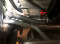
I originally shared the picture to illustrate how the hose was to be routed in front of the radiator mount and also the need to bend the power steering line bracket about 1/2" forward.

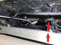
The problem I anticipate with your suggestion is the barb running straight into the radiator mount (red arrow) if the cooler is moved back. Can you estimate what sort of increase in cooling might be gained from moving the trans cooler back? Based on the numbers I recently posted in #45 the trans fluid is already significantly cooler.
 

Attachments

  • IMG_8310-2.jpg
    IMG_8310-2.jpg
    84.9 KB · Views: 887
That picture you copied is of the first or second version of the bracket where I used a bolt and stack of washers to push the cooler forward to improve fitment and hose routing. After that the bracket was redesigned to achieve the new spacing.

I originally shared the picture to illustrate how the hose was to be routed in front of the radiator mount and also the need to bend the power steering line bracket about 1/2" forward.

The problem I anticipate with your suggestion is the barb running straight into the radiator mount (red arrow) if the cooler is moved back. Can you estimate what sort of increase in cooling might be gained from moving the trans cooler back? Based on the numbers I recently posted in #45 the trans fluid is already significantly cooler.

I agree, the results listed on post 45 are good. With the placement of the transmission cooler, it gets more than enough air to cool while driving, and distance between the radiator and transmission cooler isn't. Limiting the distance between the transmission cooler and radiator is of primary benefit when in stop and go traffic, or when idling.

The radiator fan and cowling are designed to draw air through the radiator and air conditioning condenser. The closer the transmission cooler is to the radiator, the better it will be at drawing air through the cooler when idling or in stop and go traffic. My concern is that I might not get enough cooling in my 4Runner in stop and go traffic with 4 people in the car, 500 lbs of gear, and a 3,500 lb trailer.
 
I agree, the results listed on post 45 are good. With the placement of the transmission cooler, it gets more than enough air to cool while driving, and distance between the radiator and transmission cooler isn't. Limiting the distance between the transmission cooler and radiator is of primary benefit when in stop and go traffic, or when idling.

The radiator fan and cowling are designed to draw air through the radiator and air conditioning condenser. The closer the transmission cooler is to the radiator, the better it will be at drawing air through the cooler when idling or in stop and go traffic. My concern is that I might not get enough cooling in my 4Runner in stop and go traffic with 4 people in the car, 500 lbs of gear, and a 3,500 lb trailer.

My off road trailer is nowhere near as heavy but along with it I did haul an extra 400 pounds of water and 120 pounds of fuel uphill at speed and also offroad in sandy washes.

I'm looking forward to seeing how you get at that hose clamp!
 
My off road trailer is nowhere near as heavy but along with it I did haul an extra 400 pounds of water and 120 pounds of fuel uphill at speed and also offroad in sandy washes.

I'm looking forward to seeing how you get at that hose clamp!

I have an order in for the mount and Hayden 698 cooler. When it arrives, I will install and post pictures.

I should be able to put it together without removing the bumper/grill, but I am considering for more room.
 
I went through my phone and downloaded all of the final install pictures. Some have been previously shared so there may be some repeats.

These include:

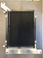
The cooler mounted on the bare bracket to illustrate the bolt locations as compared to the inlet and outlet tubes. The Hayden has lots of mounting holes so new ones could be drilled in the bracket.

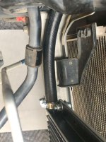
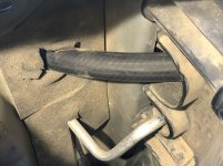
The routing of the lower hose between the engine radiator bracket and the power steering line and bracket.

One with two opposing red arrows indicating how the new bracket fits under the vertical hood latch support bracket.

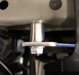
Illustration of how the supplied bolt spacer is installed
 

Attachments

  • IMG_E8491-1.jpg
    IMG_E8491-1.jpg
    132 KB · Views: 765
  • IMG_8529-1.jpg
    IMG_8529-1.jpg
    109.5 KB · Views: 767
  • IMG_8508-1.jpg
    IMG_8508-1.jpg
    73.2 KB · Views: 786
  • RZAM7520.jpg
    RZAM7520.jpg
    44.5 KB · Views: 897
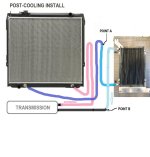
I am going to attempt to share how the hoses should be routed with a diagram that tries to capture the stock routing and the ideal way to insert the cooler. I'm sure I'll trigger as many questions as I am trying to answer!

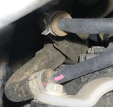
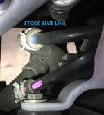
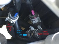
The stock setup includes two steel "jumper" tubes that route from the upper corner of the engine radiator on the passenger side, then down to the lowest area of the engine radiator facing the engine. Toyota marks these with pink and blue paint at the higher point. The "pink" colored line remains unchanged. On the diagram the purplish colored line is the stock steel line that routes up to "Point A" where we insert the trans cooler.

I've read in a few sites (including Hayden's) where they recommend the trans fluid flows into the lowest point of the cooler and exits the higher point. Probably to create a "pool" of fluid in the radiator that rises upward and "overflows" downhill towards the transmission. That approach might force any air bubbles up and out such that the cooler is always void free.

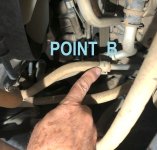
The OEM "blue" line is where the cooler is inserted. I found a picture that I marked up where the OP used a union to connect one of the cooler's hoses to a line at I point I show as "Pint A". The easier option might be to just home run the cooler's rubber hose down to a point I show as "Point B" which is the steel tube running back to the transmission. This approach would leave the steel jumper tube capped off (abandoned) rather than use a couple and route trans fluid the extra distance.

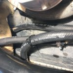
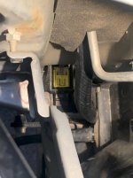
I also have a couple of pictures showing how the hoses route from the cooler and make a right angle turn through the foam covers on the mounting of the engine radiator. The lower cooler line is the one that routes beneath the steel power steering cooling line and passes above the yellow labeled sensor..
 

Attachments

  • FLOW THROUGH COOLER.jpg
    FLOW THROUGH COOLER.jpg
    99.6 KB · Views: 838
  • Blue hardline.JPG
    Blue hardline.JPG
    100 KB · Views: 865
  • New_blue.jpg
    New_blue.jpg
    75.8 KB · Views: 903
  • IMG_8519-1.jpg
    IMG_8519-1.jpg
    133.1 KB · Views: 859
  • IMG_8531-1.jpg
    IMG_8531-1.jpg
    66 KB · Views: 904
  • IMG_8532-1.jpg
    IMG_8532-1.jpg
    95.4 KB · Views: 865
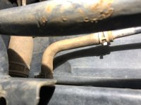
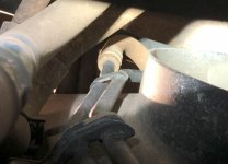
Here are what the stock steel "jumper" tubes look like
 

Attachments

  • IMG_8511-1.jpg
    IMG_8511-1.jpg
    81.7 KB · Views: 1,376
  • IMG_8517-1.jpg
    IMG_8517-1.jpg
    49.9 KB · Views: 772
  • IMG_E8524-1.jpg
    IMG_E8524-1.jpg
    72.4 KB · Views: 876
teotwaki,

I think you might have plumbed the cabling the way I was considering.
Are these the transmission hose/lines near the top of the radiator on the passenger side once the transmission cooler has been added?

410936d1712322309-trans-cooler-mount-need-kansas-5th-gens-new-product-fitment-new_blue-jpg
 
Last edited:
teotwaki,

From your below picture of the elbow hose exiting the radiator. This is the point on the FJ Cruise where people tie the transmission cooler into the system. I thought you tied into the system at this point.

410943d1712324091-trans-cooler-mount-need-kansas-5th-gens-new-product-fitment-img_8511-1-jpg
 
The kit arrived yesterday. I ordered the Iconic mount with the Hayden 698 cooler. I am prepping the kit for an install this weekend. I added a push nut bolt retainer to hold the spacer, though it isn't needed (just makes things a little easier). I also added a washer to use between the nut and mounting point, also not really needed.

I have a couple questions though.
Where does the edge trim guard that came with the kit go?

How did others add the extra transmission fluid to the system? Did you fill the external transmission cooler when connecting the hoses, or did you top the system off with a quart of oil while it was running?
 
Last edited:
I'm planning to install mine this weekend (if I feel well enough). I ordered some spring action hose clamps from Toyota to link to the OEM transmission return line (those arrive on Monday this week). The Toyota camps are Not required, but I wanted to match the style in the engine compartment to make it easier in case I need to stop using the external cooler for any reason. I also picked up some Toyota WS ATF last Friday. I ordered an inexpense hose pump to make it easier to top the transmission off.

Amazon.com
 
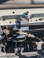
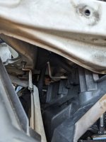
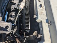
Installed my cooler yesterday. It was definitely a pain getting your hands in tight spaces and routing hoses in the engine bay but totally doable. Definitely ran into issues with spacing and mounting etc since I have a winch in the way. I had to modify the mount a little bit. I'm going to monitor it to see if there's any issues with rubbing etc. I think later on I will totally reverse the whole cooler on the mount and give it more room, but that's down the road.PXL_20240424_203525573.jpgPXL_20240426_153722775.jpgPXL_20240424_203529014.jpg

Sent from my Pixel 6a using Tapatalk
 

Attachments

  • PXL_20240424_203525573.jpg
    PXL_20240424_203525573.jpg
    124.1 KB · Views: 996
  • PXL_20240426_153722775.jpg
    PXL_20240426_153722775.jpg
    72.3 KB · Views: 977
  • PXL_20240424_203529014.jpg
    PXL_20240424_203529014.jpg
    105.6 KB · Views: 988

Members online

Forum statistics

Threads
278,315
Messages
3,554,125
Members
248,016
Latest member
Advally Service

Trending content

Back
Top