This was great. After waffling for months on spending the extra money for factory switches, I finally decided to do this. For the record I have a 2005 4WD V8.
A slight variation:
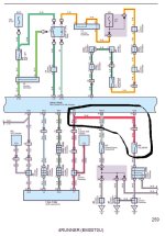
After having the dash apart & running the wire to the 4wd control ECU as shown, I noticed an unused connector (blue) on the left side of the dash where the switches go. I tracked it down in the wiring diagrams & discovered it is the connector for the "Trac Off" switch [which I believe is for 2wd only variants]. Being curious I looked at the diagram further & realized that the red with white wire for Trac Off runs to the skid control ECU. The red with blue wire that we tap at the 4wd ECU for this modification ALSO connects to the skid control ECU. Same wire. Hmmmm...
So, I purchased a used "Trac Off" switch and for ha ha's, I connected it to the empty blue connector & (breath hold...) tried it. Nothing. I confirmed that on my 4wd, the "Trac Off" switch has no effect on the condition of VSC (or any thing else that I could tell). Now on the 2005, the skid control ECU is in the engine bay at the brake fluid reservoir (I think its under the dash on earlier models???). I confirmed that the red & white wire in the connector (at position #43) at the skid control ECU is in fact the same wire at the blue connector behind the dash. The wire I needed to tap (red/blue) was at position #27 of the same connector. I simply cut the red/white wire close to the connector & tapped it into the red/blue wire a couple inches from the connector (I had to remove some of the loom & tape to tap it there). I sealed the connection (heatshrink tubing) and re-taped the harness & replaced the loom.
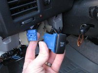
So now I have a factory looking switch all connected to work the VSC off mod. The ground needed & illumination wires are already in the blue connector so the total installation was VERY easy!
But wait, the "Trac Off" switch is only a momentary switch you say. Well fortunately some one else had shown (I think on this forum - will research it) how to convert a momentary switch into an on/off one. Not that hard. Briefly if you can take apart any on/off switch, you will see that it has a very thin wire across it and a slightly thicker "Z" shaped (kinda "Z" shaped anyway - maybe describing it as two offset bends is better?) that rests on the first wire. Simply duplicate these pieces (I used two thin pins of the same diameter). It is important to DUPLICATE the "Z" shaped pin as closely as possible - a little trial & error. Remove the white plastic piece inside the momentary switch (you will see the on/off switch does not have that piece) & put the switch back together. Voila! An on/off "Trac Off" switch.
Now the purists will say that it's only turning the VSC off & not the traction control off. I know; I would have preferred to use a "VSC off" switch but I know what my switch does if I use it. For the "plug & play" ease of installation this slight discrepancy was worth it to me.
A word of caution if anyone proceeds with this. I originally used copies of the 2003 wiring diagram. For that year, the red/blue wire at the skid control ECU is listed at position #3 & the red/white wire is at #26. The 2006 wiring diagram mirrors what I found on my 2005 (YMMV!). Please confirm what wires you cut / tap beforehand! For mine, on the skid control ECU connector #41 is light green, #42 is RED/WHITE, #43 is also RED/WHITE, and #44 is white/green. With the connector disconnected from the skid control ECU check for continuity between the red/white at #43 & the red/white at the blue connector for the trac off switch (WITHOUT the switch connected to it).
Thanks go out to CJ3Flyr & Andries (at T120) for giving me the courage for this!
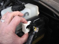
In the 1st picture below is the connector for the skid control ECU. To disconnect it, pull the white locking piece forward (about 1/2 way in photo) & pull the connector itself easily toward the fender at the same time.
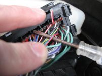
In the 2nd picture my fingers point to the red/white wire I cut (connect the other end - not seen here - to the red/blue wire) & the red/blue wire to connect/splice/solder it into, the one that runs over the screwdriver in the picture NOT THE BLUE WITH RED AT THE TIP OF THE SCREWDRIVER. The black cover that snaps on (you can see it in the 1st photo) has been removed.
The 3rd shows the switch I used that plugs into the factory harness without modification to the plug or wiring.