Wild_Turkey 2015 T4R SR5 Premium Build

wild_turkey

New member
Wild_Turkey 2015 T4R SR5 Premium Build

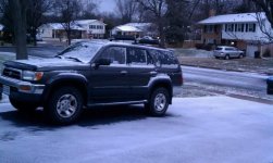
Welcome to my build thread! While I am new to the T4R forum, I am not new to 4Runners. I loved my 1998 3rd Gen Limited 4x4. We sold it to purchase my wife an SUV (Lexus RX 450H) with more modern safety features, and I regretted it.

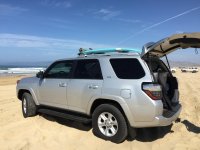
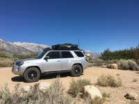
After bouncing around between sport sedans and coupes, I decided to go back to a 4Runner and purchased a 2015 SR5 Premium 4x4 with a 3rd row. I love it!

The purpose of this build thread is to document my build lessons learned. I am super thankful to the guys who take the time to photo and document their installs, so hopefully mine will be even half as helpful.

Mods to-date:

EXTERIOR

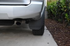
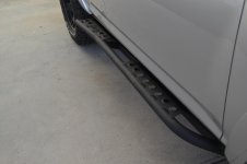
· C4 Fabrication Sliders with Step Plates
· C4 Fabrication Fuel Tank Skid
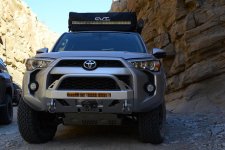
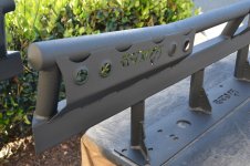
· C4 Fabrication Lo Pro Winch Bumper
· TRD Front Skid
· 3M Ceramic Window Tint 22%
· Baja Flat Utility Rack (SOLD)

LIGHTING

· KC HiLites 20” C-Series
· KC HiLites 40” C-Series (SOLD)
· KC HiLites 3” C-Series Flood (Mounted as ditch lights)
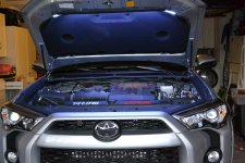
· Anti-Dark Hood Light

INTERIOR

· Toyota All-Weather Floor Mats
- Canvasback Cargo Liner
- 3rd Row Half Conversion Cargo Fridge Slide - 6 Seater T4R

COMMS AND ELECTRONICS

· Cooper Bussmann Offroad powering all accessories
- Air On Board (AOB) Switches (x5)
· Midland 75-822 CB Radio

SUSPENSION, WHEELS AND TIRES

- Bilstein 6112/5160
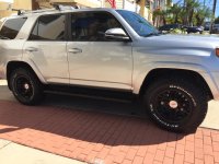
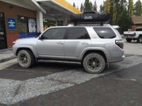
· FN F(x) Pros matte black
-17x8 6 on 139.7

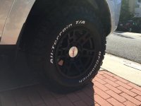
· BF Goodrich All Terrain KO2
-275/70-17 Load E

MISC

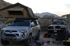
· CVT Mt Shasta Roof Top Tent (SOLD)
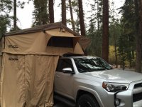
· James Baroud Grand Raid Roof Top Tent
· ARB CKMA12 Compressor for on board air
- Rear Diff Breather Mod - Tail Light
- $6 DIY Rear Window Screens
 

Attachments
  • 3rd Gen T4R.jpg
    3rd Gen T4R.jpg
    50.6 KB · Views: 5,755
  • 4Runner Pismo.jpg
    4Runner Pismo.jpg
    124.8 KB · Views: 6,138
  • DSC_0886.jpg
    DSC_0886.jpg
    134 KB · Views: 6,348
  • Alabama Hills.jpg
    Alabama Hills.jpg
    136.4 KB · Views: 3,355
  • IMG_2202.jpg
    IMG_2202.jpg
    137.6 KB · Views: 3,218
  • DSC_0415.jpg
    DSC_0415.jpg
    132.7 KB · Views: 2,629
  • DSC_0445.jpg
    DSC_0445.jpg
    136.4 KB · Views: 2,337
Last edited:
Register to hide this ad
Fn fx pro wheels and bfg at ko2

Really happy with the way this setup looks. I have been thinking (obsessing) about these wheels for a few months now and I couldn't be happier.

I talked to Dustin [MENTION=85422]FNWheels[/MENTION] to check availability and he confirmed he had the black f(x) pros in stock. I am local, so I met him at his shop to pick them up and save on shipping.

People have said it before but I will reiterate it here...Dustin is a great guy and a true professional! He really does go the extra mile for his customers.

He hand inspected each wheel with me to make sure everything was perfect. I mentioned that I read a post about the TRD center caps falling out due to the plastic tabs breaking. He explained that the retaining/tension ring should be removed prior to installing so the plastic tabs can flex, then install the ring from the back once the center cap is in. It makes perfect sense and it was the first time my tire installer had ever heard that. They are making that their standard process going forward.

In all of the vehicles I have owned, this is the first set of after-market wheels I have purchased. Dustin recommended that I go over the wheels with the installer to show them that the wheels were new and flawless, which helps keep me covered (as much as possible) in the event something happened during the installation. Again, it makes total sense, but something I would not have done had he not recommended it.

I also got a smoking deal on the BFG's...4Wheelparts.com has a special going for $165.99 per tire (LT265/70R17, Load C BFG AT KO2) and I had the tire shop I have been going to for years do the best they could to price match. (Note that the 4wheelparts installation cost is a bit pricey, so even though the per tire price was more, the out the door cost was slightly less).
 

Attachments

  • IMG_1564.jpg
    IMG_1564.jpg
    131.9 KB · Views: 6,929
  • IMG_1553.jpg
    IMG_1553.jpg
    129.3 KB · Views: 5,411
  • DSC_0897.jpg
    DSC_0897.jpg
    126.1 KB · Views: 5,106
Last edited:
Cooper bussmann offroad & aob switches

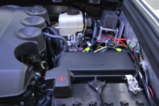
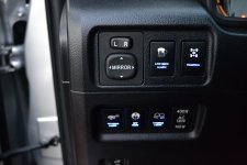
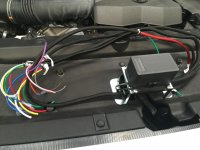
I just wired up the Cooper Bussmann Offroad and AOB switches over the holiday weekend. Still have some cleanup to do, but all of the relays are working, including the dimmer function.

Cooper Bussmann Offroad

I purchased the Cooper Bussmann Offroad from Ebay as it fully wired the Cooper Bussman. I was very impressed with the quality of the work as it came well labeled, quality and proper gauge wiring, and fully loomed. Cooper Bussmann Offroad

I was looking at the sPod, Cooper Bussmann, and the Blue Sea Fuse Block. I went with the Bussmann for the following reasons:

sPod: sPod is definitely a cleaner install, but spendy. I couldn't justify the extra cost since I planned to buy the AOB switches for an OEM look. The 6 switches included with the sPod would have basically been wasted. I also only had 5 open switch knockouts, so sPod was overkill for me.

Blue Sea: Blue Sea seemed like a reasonable approach, but it lacked the relays. So I would have had to cludge something together and the install would have been messy for my application.

Cooper Bussmann Offroad: This was the best balance of cost, functionality, and clean install for my application. There were 5 fused switch relays (I have 5 open switch knockouts!), 5 additional fused unswitched leads, and was available all wired up for less than half the cost of the sPod. This allowed me to use the cost difference on OEM style switches.

My plan was to complete the wiring for all 5 switches. I only have an ARB compressor hooked up at the moment, but figured this would make future accessories easy to wire in without having to open the console every time.

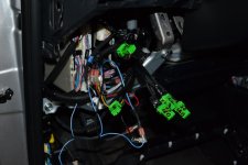
I had to move 1 switch to the right of the steering column (formerly reserved for the "party mode" switch) since I wanted all 5 AOB switches on the left column switch panel. The problem is, the factory harness isn't long enough to reach to the right column. So I decided to relocate the wiper heater switch since it had a dimmer function. Since I had to extend 1 switch harness AND find a way to tap into the dimmer circuit, it may as well be the wiper heater switch. In for a penny, in for a pound!

1 of the AOB switches was sticking, so I had to go back in anyway. In my haste, I had also forgotten to hook up one of the OEM switches back up! After seeing [MENTION=109515]YodaPride[/MENTION] wiring harness, I was ashamed of my rat’s nest and built a wiring harness. It cleaned up the wiring significantly since 3 of the 4 wires on each AOB switch has a common destination.

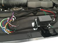
Mounting the Cooper Bussmann was fairly easy. I used a piece of 4” aluminum angle as the bracket and mounted it to the driver’s side fender using 2 existing M8 tapped holes. I also tapped the Bussmann mounting locations on the bracket to make it easier to install.

Pulling the wiring through the firewall was fairly straightforward.
- Cut the nipple off the plug on the driver’s side firewall
- Insert coat hanger
- Attach wiring loom to coat hanger using a healthy amount of tape
- Tip: Apply a generous amount of grease to the hanger and wiring loom (I used white lithium grease). This helped pull the wiring through with ease
- Tip: Attach wiring connectors AFTER the wiring loom is through the firewall. Just less to pull through

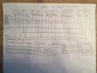
I've included a few pictures from my install. I sketched out a quick wiring diagram to keep my head straight. Hope it helps.


AOB switch wires:

Red – Relay
Green – Constant 12v source (Used un-switched output from Cooper Bussmann)
Blue – OEM Green Dimmer wire
Black – OEM Gray Dimmer wire
 

Attachments

  • IMG_1646.jpg
    IMG_1646.jpg
    125.9 KB · Views: 5,759
  • DSC_0835.jpg
    DSC_0835.jpg
    118.8 KB · Views: 5,529
  • IMG_1639.jpg
    IMG_1639.jpg
    135.2 KB · Views: 5,477
  • DSC_0896.jpg
    DSC_0896.jpg
    132.7 KB · Views: 5,512
  • DSC_0895.jpg
    DSC_0895.jpg
    129.8 KB · Views: 9,450
Last edited:
On board air: Arb ckma12 compressor

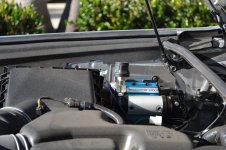
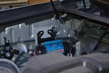
I decided to clean up my install on the compressor. I originally rough cut the adapter plate for a dry fit, but it was installed at that point and we were going on a trip. I've been using it for the past 6 months, but decided to update some pictures since I trimmed the adapter plate and cleaned everything up. I added some rubber washers to the backside to dampen the vibration a bit more.

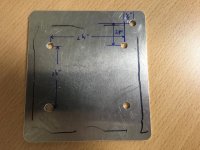
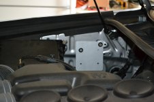
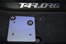
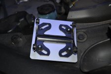
This install was fairly straightforward. I decided to mount the compressor on the passenger fender wall using the existing M6 tapped holes. In order to use the existing holes, I made a butch plate out of 0.125” Aluminum. We tend to have scraps laying around the machine shop of my company.
For piece of mind, I mounted 1 of the bolts through the compressor foot, butch plate, and into the fender wall. This provides a very secure and rigid mounting method. The other 3 feet were mounted to the butch plate using M6 bolts and nylock nuts. Finally, there is 1 more M6 bolt going through the butch plate into the fender wall.

Here was the sequence for mounting the compressor:

1) Measure and drill holes in the butch plate (see dims written on plate in pic)
2) Remove the 2 top-oriented Allen screws holding the compressor to the mounting feet
3) Loosen the other 2 Allen screws enough to allow the compressor to be flipped 180 onto it’s back (think like opening a clamshell)
4) Install M6 bolts and nuts to secure 3 of the mounting feet to the butch plate, leaving 1 foot free to be bolted to the fender wall
5) Remove air filter box to provide working space
6) Secure butch plate to fender wall using qty 2 M6 bolts (1 will go through the remaining mounting foot)
7) Rotate compressor back up and re-install 2 Allen screws to secure compressor to mounting feet
8) Tighten lower 2 Allen screws

Wiring:

Follow the directions on the wiring and you should be fine. I ran into a little trouble because I hooked the black wires to chassis ground. They actually need to go to the battery negative terminal. I believe this is because the ARB compressor is a DC motor.

I routed the wire harness along the firewall and secured it to an existing wiring harness using zip ties. Once it was routed, I cut the excess wiring. Since I used the Bussmann relay and AOB switch, I did not need the harness connector with the red, black, green, and yellow wires. I ended up using that as my wiring harness extension to move the OEM wiper heater switch to the right of the steering column

Hook all red wires together and connect to Bussmann relay output.
Hook all black wires together and connect to negative battery terminal.
I left the pressure switch relay intact and in the wiring harness.

It works like a charm! It takes me 10 minutes to inflate my 4 LT265/70R17 BFG AT KO2’s from 15psi to 39 psi.
 

Attachments

  • DSC_1099.jpg
    DSC_1099.jpg
    135.4 KB · Views: 3,745
  • FullSizeRender.jpg
    FullSizeRender.jpg
    134.7 KB · Views: 2,941
  • DSC_0170.jpg
    DSC_0170.jpg
    123.5 KB · Views: 3,011
  • DSC_0173.jpg
    DSC_0173.jpg
    132.1 KB · Views: 2,999
  • DSC_0174.jpg
    DSC_0174.jpg
    130.5 KB · Views: 3,044
  • DSC_0175.jpg
    DSC_0175.jpg
    128.5 KB · Views: 2,991
  • DSC_0176.jpg
    DSC_0176.jpg
    130.6 KB · Views: 3,032
Last edited:
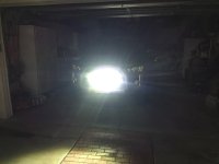
20" led light bar behind grill: No drilling!

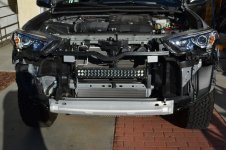
For my build, I have been trying to keep my mods as bolt on as possible and minimize irreversible changes, such as drilling. There seem to be plenty of factory-tapped holes to tie into.

So how to install the LED light bar behind the grill without drilling holes? Most of what I read in the forums involved drilling holes in the front bumper/crash bar. I decided I was going to tie into the upper front bumper support. It just so happens that 2 of the push pins line up perfectly with my 20” KC HiLites feet.

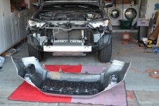
First things first, how to remove the front bumper on the 5th Gen? There were some threads out there that talk about this, and they get you most of the way there. Hopefully this helps a little. Remember, the nipple is the most important piece…

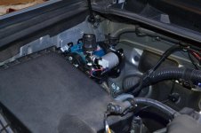
1) Remove the engine cover by removing all of the push pins securing the plastic cover. Simply push the center down, then pull the pin out.
2) There is a second style push pin holding in the front bumper. These require a small screwdriver to pull the center of the pin up, then pull the pin out.
3) Remove the 10mm bolts (3 in each fender, 6 on the bottom of the bumper, and 1 on the hood latch cross member)
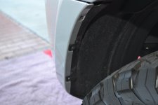
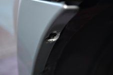
4) The tricky part is around the 3 bolts removed from each fender. The top bolt location has a plastic nipple holding the fender in place (see picture). You need to pry the plastic fender over this black plastic nipple. In my case, the silver portion needs to go over the black nipple.
5) The remaining 2 bolt locations in each fender have a plastic clip. Pull the fender free of these clips
6) Repeat steps 4 and 5 for the other fender
7) Tip: Remove the wiring harness from each foglight. Believe me, it is easier to do this now before you are holding the bumper in your hands.
8) Tip: Lay out a moving blanket or something to lay the bumper on once removed
9) Start on one fender wall and begin removing the bumper by pulling out and up. At this point, plastic clips are the only things holding the bumper in place. Keep going all the way around until the bumper is free.

Fabricating the Brackets

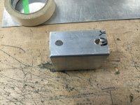
I decided to make support brackets using 1.5x3” box tubing, 3” in length. This allowed me to tie each bracket into 2 locations on the support frame (there is an unused slot 2” from the push pin location). I wish I knew how to caption the photos…this one could get messy.

I bought a 12” piece of 1.5x3” aluminum box tubing for $10. I cut this down into 3” sections. If I had it to do over again, I would cut 4” sections. I am fortunate in that I have a really nice machine shop in my building. I don’t know how to use any of it, but people like me. Too bad I didn’t get a video of the machine we used to cut the tube, but I snapped a picture.

The guys were a little light before the holidays, so I also had them drill and slot the brackets on the bridgeport. Too bad the video won't upload.

One side of the bracket has a 0.320” hole and .0320x0.420” slot, 2” on center. These will be used to secure the bracket to the frame with M8 bolts. The other side has 2 0.250” holes drilled, 2” on center. Only 1 will be used, but it makes the brackets interchangeable on either side. This is used to secure the KC LED bar mounting foot with a M6 bolt. The KC bracket drops the light 1.5”. Add this to the 3” box extrusion and it’s the perfect height below the plastic cross member to reveal the light in the lower grill section.

LED Installation

I test fit everything and my biggest concern turned out to be true…the support bar flexed front to back with the weight of the light bar. Doh! I needed something to stiffen this up. My neighbor helped my bend some sheet metal and we fashioned up a support arm that tied into the side of the light bar and below into an existing bolt below the radiator. You can kind of see it on the driver side of the light bar. I would have rather done one on each side to be symmetric, but the passenger side would have been really close to the A/C line, so I opted for just 1 support arm. It’s super solid and I’m stoked with the “no drilling” install. I wired this up to my previously installed Bussmann and I was in business.

A couple of last tips on the mechanical attachment: Use a 30mm length M8 bolt in the 2 locations that interface the plastic clip on the upper front bumper. 25mm does not give enough thread engagement and 35mm is too long to get the plastic clip over. I also have a nut as a spacer between the top of the fabricated bracket and the support frame. This is because the support frame notches up for the bumper attachment. Run the bolt up from the bottom and the spacer nut helps hold it in place while you position the bumper and clips back in place. Once the plastic clip is over the bolt, secure with a nylock nut and fender washer.
 

Attachments

  • DSC_0877.jpg
    DSC_0877.jpg
    114.8 KB · Views: 5,007
  • DSC_0878.jpg
    DSC_0878.jpg
    124.9 KB · Views: 5,038
  • DSC_0879.jpg
    DSC_0879.jpg
    140.1 KB · Views: 4,991
  • IMG_1681.jpg
    IMG_1681.jpg
    132.3 KB · Views: 4,971
  • IMG_1694.jpg
    IMG_1694.jpg
    136.8 KB · Views: 4,991
  • DSC_0885.jpg
    DSC_0885.jpg
    132.9 KB · Views: 5,002
  • IMG_1701.jpg
    IMG_1701.jpg
    150.2 KB · Views: 4,990
  • DSC_0886.jpg
    DSC_0886.jpg
    134 KB · Views: 5,073
Last edited:
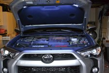
Anti-dark hood light

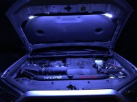
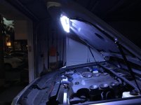
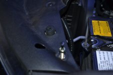
This Anti-Dark Hood light is awesome! It throws off so much light and is super easy to install. Follow the included directions and you are set. You do have to open up one of the holes in the plastic engine cover as well as the sheet metal hole below. The Anti-Dark push switch needs to have good contact with the metal in order to ground and complete the circuit. The last photo shows where I located the push switch.
 

Attachments

  • IMG_1705.jpg
    IMG_1705.jpg
    124.8 KB · Views: 5,174
  • IMG_1704.jpg
    IMG_1704.jpg
    131.2 KB · Views: 5,236
  • DSC_0888.jpg
    DSC_0888.jpg
    126.3 KB · Views: 4,791
Last edited:
C4 fabrication sliders & fuel tank skid

C4 FABRICATION SLIDERS & FUEL TANK SKID

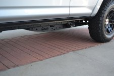
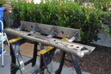
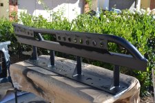
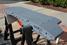
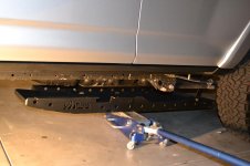
I finally was able to install my C4 Fabrication Rock Sliders and Fuel Tank Skid! These are super stout and a really well thought out design. The quality of the welds and attention to detail really shows in Caleb’s work.

I had been researching rock sliders for some time. There is a wealth of information in [MENTION=115953]HerT4R[/MENTION] thread (Consolidated Slider Thread). I reviewed the options and decided the C4 Fab sliders were for me. The details can be found on their website (C4 Fabrication), but here are the main reasons I chose the C4 Fab sliders.

Why C4 Fab?
1) 100% bolt-on design to existing tapped holes
2) The rear part of the slider kicks out to give a more functional step
3) Main slider support legs are welded in at a 45 degree angle. This helps prevent the sliders from getting hung up on sharp rocks and provides more clearance
4) Front portion of the tube is mitered at an angle, allowing you to slide up and over an obstacle. Other designs have a squared off tube attachment, which could more easily get hung up on a stump or other obstacle.
5) Price. The sliders are really well priced for all of the features designed in ($625 with step plates)

I decided to also purchase the Fuel Tank Skid to protect this vulnerable piece. Since this is also my daily driver, I did not want to go full armor and add the extra weight. While this skid is heavier than the Aluminum skids available out there, the design attributes were worth the extra weight. The other designs I reviewed left the front portion of the fuel tank still exposed. The C4 Fab design provides a full enclosure with a ramp feature in the forward approach. I am really happy with it! I also have the TRD Front Skid and that's about it for me as far as armor goes. I may consider something like RCI's TRD integration skid, but that would be it.

The sliders and fuel tank skid ship with a raw steel finish, which needs to be addressed so as not to develop rust.

Prep, Prime, Paint
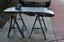
1) Clean machine oil residue off using mineral spirits. Get as much off as possible to make sanding easier.
2) Abrade the surface using 80-120 grit sandpaper. I used 100 grit with my Makita vibrating sander. This worked great on the fuel tank skid since it is mostly flat surfaces. The sliders were a bit more challenging as there are more pieces to address and some tight nooks. I did my best to get down to the raw metal.
3) Blow loose dust particles off using compressor or air gun
4) Wipe down surface again. I used alcohol.
5) Scotch brite surface until metal becomes brighter color. This ensures you get the residual oxidation off.
6) Blow loose dust particles off using compressor or air gun
7) Wipe down surface again. I used alcohol at first, but then found the Duplicolor prep spray worked better.
8) Applied 3 coats of Rustoleom primer (RTA9205). Let cure 24 hrs.
9) Applied 6 coats of Duplicolor flat black paint (DA1605). Let cure 7 days
10) Applied 5 coats of Duplicolor Bed Armor. This was done on the sliders only to give some extra traction when using the step plates in mud or snow. This stuff took forever to dry. I let it cure for 5 days.

I’m sure I made some mistakes when painting as this was the first time I’ve ever painted something like this. I have painted my house, but never raw steel. I think I was supposed to sand the cured paint before applying the bed armor, but we will see how it holds up. It was pretty windy a couple of days when I was priming/painting. I am sure I wasted at least 3 cans of paint due to the wind.

This was A LOT of work! I wore a respirator the whole time due to the metal debris. Sure I saved a couple of bucks and got some experience and satisfaction from DIY. But if I had it to do over again, I would have sent the sliders out to be Linex’d.

Installation
The installation was pretty straightforward.

Fuel Tank Skid – Attach the 3 hanger arms to the skid first. Use a floor jack to move it into place. Once you have all the factory bolts holding the skid in place where it fits good, then tighten up the mounting legs where they attach to the skid. I ran into a little issue where I had everything shifted to one side of the slot, which provided very little clearance from one of the bolts to the fuel tank. I loosened it back and up and shifted things to the other side and I have enough clearance now. I could also flip the bolt around since the bolt head is lower profile than the nut/lock washer.

Sliders - As for the sliders, they are pretty easy. You just have to remove the forward most e-brake cable bracket bolt so that the bracket hangs loose. Twist the bracket up so it doesn’t snag on the sliders as you lift them into place. All of the 8mm bolts that came with the sliders thread into the holes in the side of the frame rail. Once the slider is in place, the e brake bracket gets bolted back into the same hole on top of the slider plate.

That’s it! I am really happy with the quality of these C4 Fabrication products and with the install. I highly recommend taking a look at these.
 

Attachments

  • DSC_0823.jpg
    DSC_0823.jpg
    135.7 KB · Views: 4,923
  • DSC_0827.jpg
    DSC_0827.jpg
    130.3 KB · Views: 4,931
  • DSC_0868.jpg
    DSC_0868.jpg
    125.8 KB · Views: 4,893
  • DSC_0870.jpg
    DSC_0870.jpg
    130.9 KB · Views: 4,938
  • DSC_0838.jpg
    DSC_0838.jpg
    145.2 KB · Views: 4,918
  • DSC_0853.jpg
    DSC_0853.jpg
    145.5 KB · Views: 4,887
  • DSC_0883.jpg
    DSC_0883.jpg
    134.5 KB · Views: 4,936
  • DSC_0901.jpg
    DSC_0901.jpg
    133.7 KB · Views: 4,833
Last edited:
Cvt rtt mt shasta & storage

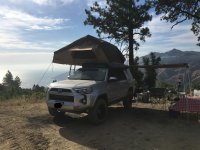
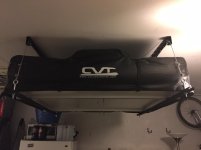
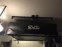
My wife was talking about getting a new tent because she did not like the fact that she couldn't stand in my backpacking tent. She wanted one of the family tents, but I convinced her we should get a RTT with an annex.

So we got the CVT Mt. Shasta! It's great. The annex is a bit of a pain to setup, but if it keeps the peace, I'm happy to do it.

Nothing too special about our install. I currently have it loaded on some Yakima bars using the Yakima Snaparounds (x4). This holds it pretty well and makes it easier to load.

I also purchased a Racor PHL-1R Pro HeavyLift 4-by-4-Foot Cable-Lifted Storage Rack. This keeps the tent out of the way when not in use and also allows me to load and unload fairly easily by myself.

Racor PHL-1R Pro HeavyLift 4-by-4-Foot Cable-Lifted Storage Rack - Ceiling Mounted General Purpose Storage Racks - Amazon.com
 

Attachments

  • IMG_1582.jpg
    IMG_1582.jpg
    138.4 KB · Views: 5,142
  • IMG_1587.jpg
    IMG_1587.jpg
    137.4 KB · Views: 6,614
  • IMG_1574.jpg
    IMG_1574.jpg
    111.9 KB · Views: 5,694
  • IMG_1575.jpg
    IMG_1575.jpg
    125.5 KB · Views: 5,180
Last edited:
Great looking set-up. I love the wheels, but I'm curious as to why you went with F(x) not the stock TRD. I'm assuming it was for a wider width? What is the backspacing on the wheel so (unfortunately, the FN site leaves much to be desired).
 
FN Wheels

Thanks! I went with the FN's over the TRD wheels for a few reasons.

1) 8" width, as you said vs 7" on TRD
2) Weight is ~ 2lbs lighter than TRD
3) Silver TRD center caps look better, IMO and are less likely to get hung up on anything since they are recessed
4) I like to support local businesses

Not sure of the wheel backspacing. The offset is 0mm, which makes the tire more flush to the fender and gives a wider stance. Give Dustin [MENTION=85422]FNWheels[/MENTION] a buzz on your question. He's super helpful.

Great looking set-up. I love the wheels, but I'm curious as to why you went with F(x) not the stock TRD. I'm assuming it was for a wider width? What is the backspacing on the wheel so (unfortunately, the FN site leaves much to be desired).
 
RTT and compressor

My wife was talking about getting a new tent because she did not like the fact that she couldn't stand in my backpacking tent. She wanted one of the family tents, but I convinced her we should get a RTT with an annex.

So we got the CVT Mt. Shasta! It's great. The annex is a bit of a pain to setup, but if it keeps the peace, I'm happy to do it. ...

Nice build thread Allan,

My wife says the same thing about my North Face, 3 pole, 3 season, 3 person tent. It's really a tent for 2 with an air mattress or 2 big comfy Thermorest pads. I tell her a smaller tent is warmer and more wind resistant than a tall tent. Last year my tent stayed put in a So Cal desert windstorm when all of my friends with their tall tents got blown away with them inside it. Heck, I can't even sit all the way up in my one man backpacking tent. :nono:

I like your hanging enclosure. That looks really handy. Nice work with the platform and garage lift.

The FnWheels look good. I might be tempted away from my 7.5" TE rims by those. Are they lighter than the stock rims?

And I like your colored spaghetti harness on the cargo floor. That electrical is all Greek to me. The ARB compressor really fits in the engine bay well. That may be the ticket for me. When I get it, I may be doing a free standing compressor stored in the back cargo space.

Again, nice build thread. I recognize Pismo Beach. Where else in California can you drive on the beach, right? Surf's up. :bounce:
 
Thanks!

The FN Wheels are lighter than the stock TE wheels and the TRD Pro wheels. Below is per Dustin [MENTION=85422]FNWheels[/MENTION]

The 17x8" / 0mm offset / 6x139.7 FN Wheels FX Pro is 23.9 lbs per wheel.

The latest 17x7" / +4mm offset / 6x139.7 TRD Pro wheel that I have weighed is 25.9lbs per wheel.*

Factory 17x7.5" wheels are approximately 27+ lbs per wheel.

I haven't driven anywhere else on the beach other than Pismo. I saw a picture of a guy driving in San Onofre, but I think it must have been by the Marine base.

Nice build thread Allan,

My wife says the same thing about my North Face, 3 pole, 3 season, 3 person tent. It's really a tent for 2 with an air mattress or 2 big comfy Thermorest pads. I tell her a smaller tent is warmer and more wind resistant than a tall tent. Last year my tent stayed put in a So Cal desert windstorm when all of my friends with their tall tents got blown away with them inside it. Heck, I can't even sit all the way up in my one man backpacking tent. :nono:

I like your hanging enclosure. That looks really handy. Nice work with the platform and garage lift.

The FnWheels look good. I might be tempted away from my 7.5" TE rims by those. Are they lighter than the stock rims?

And I like your colored spaghetti harness on the cargo floor. That electrical is all Greek to me. The ARB compressor really fits in the engine bay well. That may be the ticket for me. When I get it, I may be doing a free standing compressor stored in the back cargo space.

Again, nice build thread. I recognize Pismo Beach. Where else in California can you drive on the beach, right? Surf's up. :bounce:
 
FnWheels & driving on the beach

Thanks!

The FN Wheels are lighter than the stock TE wheels and the TRD Pro wheels. Below is per Dustin [MENTION=85422]FNWheels[/MENTION]

The 17x8" / 0mm offset / 6x139.7 FN Wheels FX Pro is 23.9 lbs per wheel.

The latest 17x7" / +4mm offset / 6x139.7 TRD Pro wheel that I have weighed is 25.9lbs per wheel.*

Factory 17x7.5" wheels are approximately 27+ lbs per wheel.

I haven't driven anywhere else on the beach other than Pismo. I saw a picture of a guy driving in San Onofre, but I think it must have been by the Marine base.

Tanks for the weight info. That helps. The Fn Wheels are 3 pounds lighter than mine.

If someone was driving around San Onofre nuclear power plant I have to guess they either work there or they broke in. Not sure if the marines even have access to the site. And driving anywhere south of there on Camp Pendleton Marine Base will get you arrested by a federal marshal. Ask me about walking up the beach at Vandenburg AFB sometime. :police:
 
Nice build so far. I'm actually doing my install on the bussman, air compressor and switches in the same locations in this weekend. Do you have any more pictures you can share on your Bussman wiring setup? I'm a beginner with this stuff so it would help me out a ton.
 
Last edited:
Bussmann wiring

Nice build so far. I'm actually doing my install on the bussman, air compressor and switches in the same locations in this weekend. Do you have any more pictures you can share on your Bussman wiring setup? I'm a beginner with this stuff so it would help me out a ton.

I bought my Cooper Bussman Offroad pre-wired. Do you have to wire up the entire Bussmann or do you already have wiring looms coming off?

I purchased mine on Ebay from Cooper Bussmann Offroad

The guy does a great job wiring everything up, and it was worth the extra $50 over the price of a blank Bussmann.

So mine came looking pretty much like the picture below. All I did was:

- Hook up the fused line to the battery, ground wire to the body chassis.
- The 12 gauge accessory wires are for your lights, compressor, etc...they stay in the engine bay
- There are 2 sets of 16 gauge wires, one for your switches and 1 for unswithed, full time 12v.
- I pulled the entire set of switch wires in through the firewall, and 3 of the unswitched.
- The unswitched leads inside the firewall are used to power your switches and future accessories that already have a switch, such as a CB radio.
 

Attachments

  • IMG_1639.jpg
    IMG_1639.jpg
    135.2 KB · Views: 1,388
Last edited:
Very clean install!!! I will be Eyeing this thread.

1 of the AOB switches was sticking, so I had to go back in anyway.

I also have a sticking switch. I have not messed with it yet, though it is really annoying. What happened with yours? Did you replace it? Fix it? get a Refund from AOB?
 
Sticky Switch

Very clean install!!! I will be Eyeing this thread.


I also have a sticking switch. I have not messed with it yet, though it is really annoying. What happened with yours? Did you replace it? Fix it? get a Refund from AOB?

Thanks, and thanks for all of your posts! A wealth of information. I uploaded a pic of the rewired harness, which I tried to model after your install.

Regarding the sticking switch, I emailed AOB and they sent replacements. I actually had 2 sticking switches, but 1 turned out to just be grabbing on the frame of the panel. I tweaked it a little with a small flat head screwdriver until it was dead center of the opening. Worked like a charm and didn't require taking it apart again. Hope that works for you, but you may want to reach out to AOB to see if they will send a replacement.
 

Members online

Forum statistics

Threads
278,316
Messages
3,554,109
Members
248,016
Latest member
Advally Service

Trending content

Back
Top