
Wiring Diagram for Light Bar, Rear Lights, and D2s

RedStripeRanger

New member
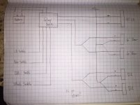
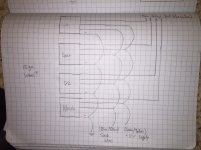
Would like some input about how I am going to wire up my lights. I dont have any experience doing any type of electrical work, so hoping someone could tell me if Im totally off. Ive looked over threads and think I have it right but Im not sure.

I am going to use:
- Rigid SR 40"
- 2 Rigid SR 6"
- 2 Rigid D2s
- Cooper Bussmann Off Road Relay Fuse Box
- AOB switches

Need to make sure this is correct:
- 16ga wires for connecting accessories
- 12ga wires for AOB switches
- Is it ok to wire the negative wires in both diagrams like that?
- Is it ok to wire the ignition and dash wires like that (second pic)?
- Suggestions on connectors?
- What weatherproof plug does Rigid use?

If there is anything else that is screaming dont do that, please let me know. Last thing I want is to cause something to overheat or catch fire.
 

Attachments

  • image1.jpg
    image1.jpg
    107.4 KB · Views: 1,716
  • image3.jpg
    image3.jpg
    126.2 KB · Views: 1,495
Register to hide this ad
Would like some input about how I am going to wire up my lights. I dont have any experience doing any type of electrical work, so hoping someone could tell me if Im totally off. Ive looked over threads and think I have it right but Im not sure.

I am going to use:
- Rigid SR 40"
- 2 Rigid SR 6"
- 2 Rigid D2s
- Cooper Bussmann Off Road Relay Fuse Box
- AOB switches

Need to make sure this is correct:
- 16ga wires for connecting accessories
- 12ga wires for AOB switches
- Is it ok to wire the negative wires in both diagrams like that?
- Is it ok to wire the ignition and dash wires like that (second pic)?
- Suggestions on connectors?
- What weatherproof plug does Rigid use?

If there is anything else that is screaming dont do that, please let me know. Last thing I want is to cause something to overheat or catch fire.

Hi RedStripe,

Maybe I missed something but... Are you using 16ga wire to the Loads/Lights but 12ga wire to your switches? That seems backwards. The 16ga wire is much smaller than the 12ga and much more current will flow through those wires to the lights/accessories than to the AOB switches (which are only used to trigger the relays using low current). Also, you'll need to run a heavier line from the battery POS and NEG (roughly 100A (MAX)/4ga "short distance") to the Rly box; the Winch will draw quite a few amps alone, and then add the lighting... Just a thought...Rgds!
 
Last edited:
Hi RedStripe,

Maybe I missed something but... Are you using 16ga wire to the Loads/Lights but 12ga wire to your switches? That seems backwards. The 16ga wire is much smaller than the 12ga and much more current will flow through those wires to the lights/accessories than to the AOB switches (which are only used to trigger the relays using low current). Also, you'll need to run a heaver line from the battery POS and NEG (roughly 100A (MAX)/4ga "short distance") to the Rly box; the Winch will draw quite a few amps alone, and then add the lighting... Just a thought...Rgds!

Thanks for the help, I had the wires mixed up. This is the fuse box I am going to use:Universal Relay Fuse Auxiliary Distribution Box Jeep Cooper Bussmann Off Road | eBay. And I am not going to be adding the Winch for some time, but want wire up the switches now.
 
"Thanks for the help, I had the wires mixed up... ...And I am not going to be adding the Winch for some time, but want wire up the switches now."

This will be great project, and since you're just becoming familiar with auto electrical systems, a great opportunity to develop your skills!
PS: I hope you'll share this project (including pictures) with the rest of us; many will benefit!

Cheers
 
(Havent started this project, life happened but getting to it this weekend)

Another question came up, noticed the wires from the rigid lights are 14ga and the relay wires are 12ga.

Is it ok to connect these together? Planning on connecting via butt connectors and waterproofing them with marine heat shrink, probably 2 layers.
 
Another question came up, noticed the wires from the rigid lights are 14ga and the relay wires are 12ga. Is it ok to connect these together? Planning on connecting via butt connectors and waterproofing them with marine heat shrink, probably 2 layers.

Hi RedStripeRanger,

Yes! Both 'Ridge and cooper-Bussman' will have sized their product's wiring based on it's 'Full load' current capability; just be sure to use a properly sized in-line fuse in your accessory's harnesses no more than six to eight inches from the battery! Best
 
Last edited:
Hi RedStripeRanger,

Yes! Both 'Ridge and cooper-Bussman' will have sized their product's wiring based on it's 'Full load' current capability; just be sure to use a properly sized in-line fuse in your accessory's harnesses no more than six to eight inches from the battery! Best

Thanks for the help! Do I need to do that even with the relay box? I have put the right fuses from the original harnesses (ie some are 10s and 15s) in the relay box.
 
Thanks for the help! Do I need to do that even with the relay box? I have put the right fuses from the original harnesses (ie some are 10s and 15s) in the relay box.

Need vs Should

Go pick up an 80A in line from a car audio shop. You can probably even find one at Walmart. They're pretty inexpensive at ~$10 with fuse and housing.
 
Thanks for the help! Do I need to do that even with the relay box? I have put the right fuses from the original harnesses (ie some are 10s and 15s) in the relay box.

Yes every fuse box, even in your home, has a 'Main Fuse' to protect the line that feeds it! So do be sure to include an in-line fuse holder/fuse no more than 8 inches from the battery! If the main supply line is 8ga then the fuse needs to be 60A max. If the line is 4ga then the fuse needs to be 100A max...etc.

Rgds
 
Yes every fuse box, even in your home, has a 'Main Fuse' to protect the line that feeds it! So do be sure to include an in-line fuse holder/fuse no more than 8 inches from the battery! If the main supply line is 8ga then the fuse needs to be 60A max. If the line is 4ga then the fuse needs to be 100A max...etc.

Rgds

Sounds good and actually added a 80amp Bussman circuit break between the battery and relay box.

Thanks again for all your help, really appreciate it
 
Rigid uses Deutsch msd 8181 connectors

I found rigid extension plugs on amazon for about $5 each, thank you for letting me know. Couldnt find the exact kind when I was originally looking.
[MENTION=83083]rigtec[/MENTION] Anticipated main load with all the lights will be 20.2 amps with all 5 lights on at once. Will be adding a 2m radio to the mix down the road. Each set of lights has its own relay. This is the relay box I got if that helps: http://www.ebay.com/itm/321764858213?_trksid=p2060353.m2749.l2649&ssPageName=STRK%3AMEBIDX%3AIT
 
I found rigid extension plugs on amazon for about $5 each, thank you for letting me know. Couldnt find the exact kind when I was originally looking.

No problem, they are a common plug apperently, I had never used them before I had installed my rigid lights. They are nice connectors.

I bought two single E2 four inch driving lights that each came with a single harness. I picked up a relayed light bar harness, a single too, oddly enough (they didn't make a double ended at the time) and sacrificed one of the original singles and spliced it in. What I am getting at :) I just bought new pins and was able to reuse everything else. Other connectors I have used in the past haven't ever been reusable, well without carefully dissecting them anyway.
 
So ran into a problem wiring everything up... Cant decide on how to get all the wires to the engine bay. I am running the lightbar and rear light wiring down each side of the windshield.

Is there a different route I should go (rear hatch) or should I drill/cut a hole in the plastic where the hood meets the body?
 
Op: how are you connecting all of your grounding wire together for the front lights? Where did you ground them?

How far from the lights?

I'm close to doing something like this in the near future but I've never done electrical work--
Thanks
 
Most people use the satellite ratio shark fin for roof top wire entry into the cab.

Found a small gap between the ditch light bracket and plastic piece where it will all fit through. Thought of doing the shark fin, didnt want to route everything from the back. I know its a cleaner look but hard to get to the wires once they are in place. My goal is to be able troubleshoot the lights if they are not working without having to tear the car apart later on.

Op: how are you connecting all of your grounding wire together for the front lights? Where did you ground them?

How far from the lights?

I'm close to doing something like this in the near future but I've never done electrical work--
Thanks

For ground going to tie all of the lights into a single wire and connect it direct to either the battery or the ground next to the battery.

Also, added busbars for all the AOB switches. Using 2 vampire fuses in the cab to run power to them. I did not want to splice any wires or do anything to mess with the original electrical incase something goes wrong with this setup while Im in the middle of nowhere. I know the car will turn on and drive (unless its the battery then Im screwed).
 

Members online

Forum statistics

Threads
278,316
Messages
3,554,120
Members
248,016
Latest member
Advally Service

Trending content

Back
Top