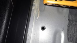
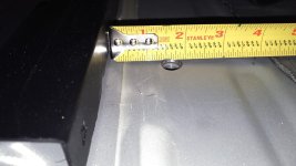
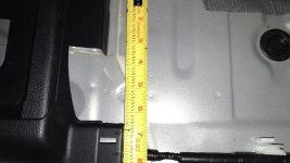
Location of hidden threaded bolt hole for sliding cargo tray

4RExplorer

New member
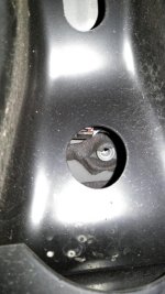
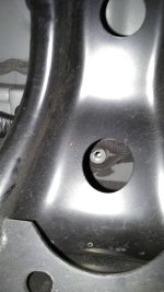
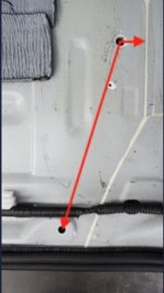
In the cargo area, I am replacing the carpet with a rectangular piece of plywood that fits between the wheel wells. To bolt its rear corners down, I drilled out the sheet metal floor to reveal two threaded holes that I believe are normally used to bolt down Toyota's slidng cargo tray (which I don't have). It took a little trial and error to find their location.

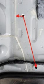
The photos show the threaded holes after I drilled them out, on the driver's side and the passenger side. In each photo, the short red arrow from the center of the threaded hole is 1 3/16" long, and the long red arrow is about 9 13/16" long. Each long arrow ends at the center of a hole near the black weatherstripping of the rear hatch (visible at the bottom of the photos).

I started with a narrow drill bit and gradually widened the hole with larger bits, and cleaned up the edges with a tiny triangular file before applying rustproofing primer with a toothpick.
 

Attachments

  • Hidden threaded hole, driver's side.jpg
    Hidden threaded hole, driver's side.jpg
    9.8 KB · Views: 1,081
  • Hidden threaded hole, passenger side.jpg
    Hidden threaded hole, passenger side.jpg
    10.7 KB · Views: 1,054
Register to hide this ad
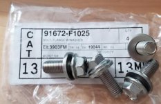
The matching bolt is an M9 x 1.25, 25mm. I had a hard time finding M9 bolts so I ordered them from Toyota for about $2 each. The Part # is 91672-F1025 and they come in a set of 4 bolts with washers.
 

Attachments

  • M9 x 1.25 bolts for sliding cargo tray.jpg
    M9 x 1.25 bolts for sliding cargo tray.jpg
    20.9 KB · Views: 1,052
Last edited:
In the cargo area, I am replacing the carpet with a rectangular piece of plywood that fits between the wheel wells. To bolt its rear corners down, I drilled out the sheet metal floor to reveal two threaded holes that I believe are normally used to bolt down Toyota's slidng cargo tray (which I don't have). It took a little trial and error to find their location.

The photos show the threaded holes after I drilled them out, on the driver's side and the passenger side. In each photo, the short red arrow from the center of the threaded hole is 1 3/16" long, and the long red arrow is about 9 13/16" long. Each long arrow ends at the center of a hole near the black weatherstripping of the rear hatch (visible at the bottom of the photos).

I started with a narrow drill bit and gradually widened the hole with larger bits, and cleaned up the edges with a tiny triangular file before applying rustproofing primer with a toothpick.

Did you happen to take any photos of the bare trunk floor? If so, I'd love to see them. I want to install an amplifier under the sliding cargo deck and will need to trim some carpet to mount it to the floor so as to allow clearance for the deck to slide over the amp. The layout of the trunk floor would be very helpful. Thanks!
 
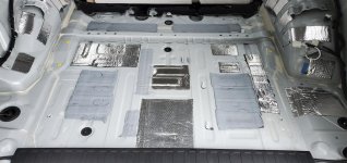
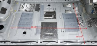
Here are a couple pictures of the cargo area floor with the carpeting and Styrofoam pad removed, taken while standing behind the rear bumper.

The side-to-side dimension of 38 5/8" is between the white lines where one piece of sheet metal overlays another (the short red arrows in Post #1 above).

The front-to-back dimension of 28 5/16" is approximate, within about 1/16". On my vehicle, the flange at the base of the crossbar near the center of the wheel wells and the row of 5 holes near the rear hatch are almost parallel, but not quite.

I took out the OEM inverter mounted on the passenger side wheel well. I also started putting in a few patches of (aluminized) soundproofing material; I won't be blanketing the whole floor with soundproofing.
 

Attachments

  • 4R cargo floor pic 1.jpg
    4R cargo floor pic 1.jpg
    107.8 KB · Views: 911
  • 4R cargo floor pic 2.jpg
    4R cargo floor pic 2.jpg
    113.6 KB · Views: 923
Yes, I think that would have worked. I initially tried accessing the nut from below, but I didn't put enough force on the punch to make a dent in the floor that was visible from above.
 
I found them by using the base of the sliding cargo tray as an indicator of where they should be.

Started with a small drill bit and then used a Dremel tool to finish the opening. I didn't want to bugger up the threads.

Finished the new bare metal with touch-up paint.
 
Here are a couple pictures of the cargo area floor with the carpeting and Styrofoam pad removed, taken while standing behind the rear bumper.

The side-to-side dimension of 38 5/8" is between the white lines where one piece of sheet metal overlays another (the short red arrows in Post #1 above).

The front-to-back dimension of 28 5/16" is approximate, within about 1/16". On my vehicle, the flange at the base of the crossbar near the center of the wheel wells and the row of 5 holes near the rear hatch are almost parallel, but not quite.

I took out the OEM inverter mounted on the passenger side wheel well. I also started putting in a few patches of (aluminized) soundproofing material; I won't be blanketing the whole floor with soundproofing.

Thank you! That helps massively! I think with a cutout in the carpet, I can get the amp low enough so the cargo tray will clear in when sliding.
 
Was gonna start a thread but since this one is the same, here's some extra info that might help since they can get rendered unusable if not lined up correctly...

Here is what you'll see from the bottom. Look at the far L and R side of the beam, through the hole in the pic of the next post, drop the spare to get access. There will be a cover of sorts like this. Just sort of stuck on there, easy enough to pull off with a pair of needle nose so not in the way.
 

Attachments

  • KIMG0270.jpg
    KIMG0270.jpg
    50.7 KB · Views: 777
Last edited:
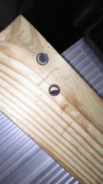
Bolt hole bottoms from underneath.... Only easy access is through the hole in the pic. I used a 9" punch from the bottom through the hole to put an indention in the floor to get an idea where to drill. As has been mentioned in other threads, start with small bit. You'll be at an angle and can somewhat center it but don't bet on it being centered when drilling from the top.
 

Attachments

  • KIMG0275.jpg
    KIMG0275.jpg
    52.5 KB · Views: 811
  • KIMG0273.JPG
    KIMG0273.JPG
    114.3 KB · Views: 775
Last edited:
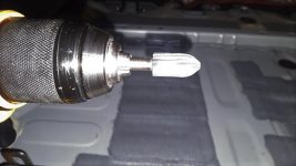
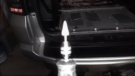
I did try larger bits to make the hole bigger but was still off from center. What worked good was having a rotary file bit for my drill. It is a pointy rounded end of sorts that lets you make the hole larger but can manage it around the edges so as not to damage the threads. The is maybe a 1/8" or so from the top of the threads to the floor so have a little room. Finished the edges with a pointed grinding attachement on the dremel.
 

Attachments

  • KIMG0279.JPG
    KIMG0279.JPG
    104.1 KB · Views: 809
  • KIMG0285.JPG
    KIMG0285.JPG
    85.9 KB · Views: 769
Able get it done clean and a few more measurements to give an idea where they are trying to locate from the top before drilling. Didn't notice til posting the pics, the top of the indention is right about the same height as the hole so may be a good reference.
 

Attachments

  • KIMG0280.jpg
    KIMG0280.jpg
    51.1 KB · Views: 773
  • KIMG0282.JPG
    KIMG0282.JPG
    120.9 KB · Views: 795
Last edited:
The center of the hole is 6.5" ish from the front of the plastic you'd see after removing the rear trim piece. Bolt thread pitch is 1.25. Can pull one of the rear seat mount bolts for reference to get new ones for the holes. Same size. Another thread I saw mentioned guys just putting 1/4 x 20 rivnuts in the holes you see exposed once the carpet/trim is removed. If you have the hardware for that, is easier but if not or prefer to use these, hope this helps.
 

Attachments

  • KIMG0283.jpg
    KIMG0283.jpg
    49.4 KB · Views: 799
Last edited:

Members online

Forum statistics

Threads
278,316
Messages
3,554,112
Members
248,016
Latest member
Advally Service

Trending content

Back
Top