4th gen ARB onboard compressor mounting bracket-CHEAP how to

4RunnerAquasport

Senior Member
Hello I have never been very good at these instructional threads but I'm giving it another shot. I searched and didn't see any cheap alternatives for a DIY compressor bracket. I would imagine someone has done something similar to this in the past, but I haven't seen these galvanized nail plates used. I did not remove the CAI for this install. All of this hardware I picked up at Home Depot for less than $25.
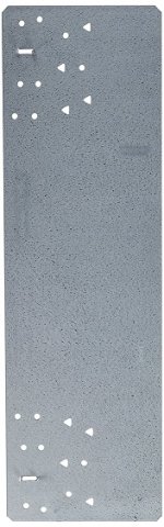
Simpson Strong Tie galvanized nail plate 16-5/16" x 5"and 1-1/4" x 9" strap
IMG_4072.JPGNail Plate.jpg


Note: All Hardware is Stainless except Nail Plate, Strap and PVC.

x2 3/8" x 2-1/2" Philips pan head bolt
x2 3/8" - 16 Nylock nuts
x2 3/8" Fender Washers
x2 3/8" Standard Washers
x2 M6 x 1.0 screws around a 1/2" long
x2 10-32 Screws
x2 10-32 Nuts
x2 #10 Standard Washer
x2 #10 Lock Washer
x2 1/2" PVC Couplings
Black Spray Paint

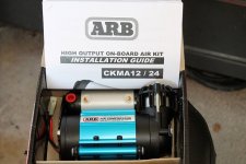
This set up could probably be modified for an ARB Twin or other brand compressor. I personally don't need a tank so this is just a basic mount for a stand alone ARB Single CKMA compressor.

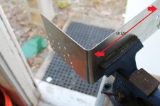
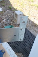
First I bent the Nail Plate so 10 1/2" will be the platform and the rest will be an upright support fastened to the fender.
IMG_4115.JPG
Next I drilled holes in the strap and nail plate and fastened the strap to the nail plate with the 10-32 hardware. I then cut about an 1 1/2" off the strap to clear the CAI.
IMG_4117.jpg
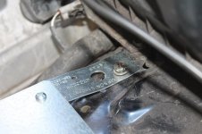
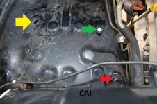
Then I drilled a hole in the strap for the M6 mounting bolt and set the nail plate and strap on the fender well behind the CAI and scouted out the best mounting options. Here is what I came up with. The upright pass. fender hole was preexisting in the plate.
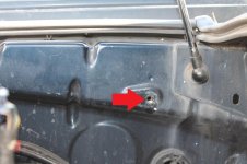
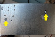
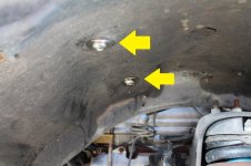
The yellow arrow was a preexisting hole I decided to use, the green arrow is a 3/8" hole I drilled, and the red arrows in this pic and the next are M6 x 1.0 preexisting holes that are bossed into the fender and fender well. I had a couple of these screws laying around from my 5th gen. These are the four mounting points I decided to use and yours may have to vary a little bit depending on what components you use and where you want it located.
IMG_4116.jpg
IMG_4119.jpg
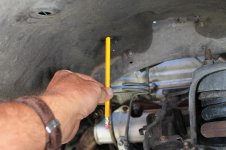
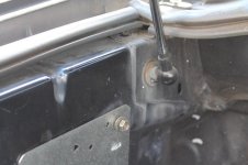
Next I set the Plate in it's position and loosely fastened the M6 bolts to get an accurate mark on the bottom through the fender well
IMG_4120.jpg
IMG_4121.jpg
 

Attachments

  • Nail Plate.jpg
    Nail Plate.jpg
    52.1 KB · Views: 3,018
  • IMG_4115.JPG
    IMG_4115.JPG
    134.6 KB · Views: 3,069
  • IMG_4117.jpg
    IMG_4117.jpg
    64.2 KB · Views: 3,094
  • IMG_4116.jpg
    IMG_4116.jpg
    79.4 KB · Views: 3,078
  • IMG_4119.jpg
    IMG_4119.jpg
    58.6 KB · Views: 3,054
  • IMG_4120.jpg
    IMG_4120.jpg
    48.2 KB · Views: 3,070
  • IMG_4121.jpg
    IMG_4121.jpg
    57.5 KB · Views: 3,059
  • IMG_4072.JPG
    IMG_4072.JPG
    92.2 KB · Views: 3,219
Last edited:
Register to hide this ad
4th Gen ARB onboard compressor bracket-CHEAP how to

Marking the bottom of the plate through the fender well
IMG_4123.jpg
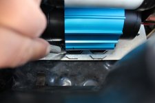
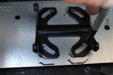
I then set the compressor in place to decide how I wanted to position the unit on the galvanized plate and marked the ARB mounting plate.
IMG_4126.JPG
Then I pulled the plate and drilled these 3/8" holes.
IMG_4124.jpg
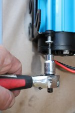
I then used a #4 allen and removed the 4 ARB mounting screws for the bracket to the compressor.
IMG_4128.JPG
Then I removed the bracket to mark the mounting holes for the plate.IMG_4129.jpg
IMG_4127.jpg
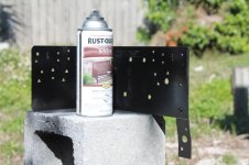
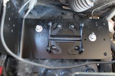
I drilled all the holes and painted the plate.
IMG_4131.jpg
 

Attachments

  • IMG_4123.jpg
    IMG_4123.jpg
    58.6 KB · Views: 3,024
  • IMG_4124.jpg
    IMG_4124.jpg
    92.5 KB · Views: 2,971
  • IMG_4126.JPG
    IMG_4126.JPG
    64.6 KB · Views: 3,013
  • IMG_4128.JPG
    IMG_4128.JPG
    121.2 KB · Views: 3,073
  • IMG_4129.jpg
    IMG_4129.jpg
    52.7 KB · Views: 3,071
  • IMG_4127.jpg
    IMG_4127.jpg
    52.7 KB · Views: 3,037
  • IMG_4131.jpg
    IMG_4131.jpg
    61.1 KB · Views: 3,012
Last edited:
4th Gen ARB onboard compressor bracket-CHEAP how to

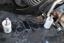
This is how the bolts thru the fender will be placed with pvc spacers and the plate will fasten down on top of these.
IMG_4125.jpg
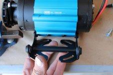
After the paint dried I fastened the ARB bracket to the plate using the supplied hardware.
IMG_4132.jpg
I then loosely fastened the plate with 3 of the 4 fasteners and then installed the spacers one at a time.
IMG_4136.jpg
These are the thru bolts on the wheel side under the fender well.
IMG_4114.jpg
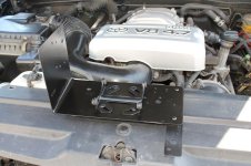
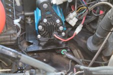
Here is everything snugged down and ready for the compressor. You will need to replace the 4 #4 allen screws that fasten the unit to the ARB bracket.
IMG_4137.jpg
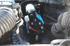
Here is the compressor installed and ready for the wiring.
IMG_4138.jpg
I have also installed one of these on my 5th gen but it was a little more involved because the fenderwell has a few differences, so I didn't take any pictures of the install. It has worked fine for more than a year.
Here is the 5th gen installed.
IMG_4139.jpg
 

Attachments

  • IMG_4125.jpg
    IMG_4125.jpg
    63.8 KB · Views: 2,988
  • IMG_4132.jpg
    IMG_4132.jpg
    69.4 KB · Views: 3,555
  • IMG_4136.jpg
    IMG_4136.jpg
    54.8 KB · Views: 2,951
  • IMG_4137.jpg
    IMG_4137.jpg
    73.4 KB · Views: 3,110
  • IMG_4138.jpg
    IMG_4138.jpg
    79.8 KB · Views: 3,579
  • IMG_4139.jpg
    IMG_4139.jpg
    79.4 KB · Views: 3,028
  • IMG_4114.jpg
    IMG_4114.jpg
    61.7 KB · Views: 3,090
Last edited:
This is a great write-up, well done. I've been looking for a plate to mount a compressor under my hood, this appears even better. :thumb:
 
This is a great write-up, well done. I've been looking for a plate to mount a compressor under my hood, this appears even better. :thumb:
Thanks Scott! The guys who have all the quality instructional threads on this forum have the real talent. I do enjoy the puzzle of fitting all this crap on my rig tho lol. Doing cheap alternatives where I can get away with them is also a good motivator.
But, documenting it so that people can get some use out of your ideas is another challenge all together. A lot of these guys on here are pretty bad ass. Glad you got some new ideas out of it!!
 
I installed my compressor this weekend using your writeup and it went great. I had a little trouble finding the Simpson plate, but finally located it at a builder's supply place. For future reference, it is a Simpson Strong Tie Nail Protection Plate, part no. PSPB516Z. LINK to Home Depot. (They did not have it at mine.)

I have a V-6 so my hole locations differed slightly. The hole you used for the strap has a bracket on mine (circled in blue), so I used the hole circled in red which is pre-tapped for an M8 bolt. I drilled my outside hole in the same spot you did.

fddV41.jpg


My plate and the finished product. I just need to wire it up and I'll be done.

s6zvRu.jpg


kVVLhy.jpg


Oh, one other thing I did: You can see how close the plate is to the rubber flex hose back towards the firewall. I was worried the plate might rub though it on rough roads, so I cut a length of vacuum hose lengthwise and put it over the edge of the plate to prevent it from rubbing through.

jKSMNL.jpg


Thanks again for the great write-up!
 
I installed my compressor this weekend using your writeup and it went great. I had a little trouble finding the Simpson plate, but finally located it at a builder's supply place. For future reference, it is a Simpson Strong Tie Nail Protection Plate, part no. PSPB516Z. LINK to Home Depot. (They did not have it at mine.)

I have a V-6 so my hole locations differed slightly. The hole you used for the strap has a bracket on mine (circled in blue), so I used the hole circled in red which is pre-tapped for an M8 bolt. I drilled my outside hole in the same spot you did.

fddV41.jpg


My plate and the finished product. I just need to wire it up and I'll be done.

s6zvRu.jpg


kVVLhy.jpg


Oh, one other thing I did: You can see how close the plate is to the rubber flex hose back towards the firewall. I was worried the plate might rub though it on rough roads, so I cut a length of vacuum hose lengthwise and put it over the edge of the plate to prevent it from rubbing through.

jKSMNL.jpg


Thanks again for the great write-up!
Sweet! Thanks YetiX!. Now that's what it's all about! I've learned a ton on this forum and it's pretty cool when you can pay it forward.
 
Can you share how you wired the compressor in? I am going to use your plans and was wondering if you had any tips for this.

The ARB comes with everything you need to wire it up. Inline fuse, relay, connectors, they make it almost plug and play. You just have to route the wires. You may have to put an extension on the +pos and -neg to have enough to reach your battery. I barely had enough, routing it through the front along the core support.
 
The ARB comes with everything you need to wire it up. Inline fuse, relay, connectors, they make it almost plug and play. You just have to route the wires. You may have to put an extension on the +pos and -neg to have enough to reach your battery. I barely had enough, routing it through the front along the core support.

Agreed. I mounted mine in the same place and there was just enough wire to get to the battery.
 
Thanks for the write up. I didn't need all the nuts and bolts you suggested because I mounted the compressor to the bent plate using the hardware that ARB provided, but I wouldn't have tackled this without your guide.

vEpd4Dk.jpg
 
[MENTION=134300]taxzz[/MENTION] That's what it's all about! The idea is there, but how people apply it to their rig with what they have to work with is the coolest thing about it. So many different adaptations can spring up from one basic simple idea. Love this forum!
 

Members online

Forum statistics

Threads
278,312
Messages
3,554,089
Members
248,016
Latest member
Advally Service

Trending content

Back
Top