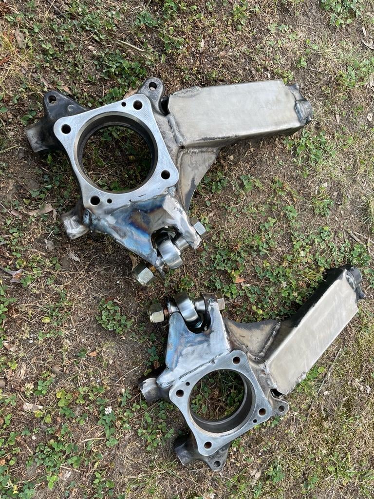
aemravan's build thread - project TacoRunner

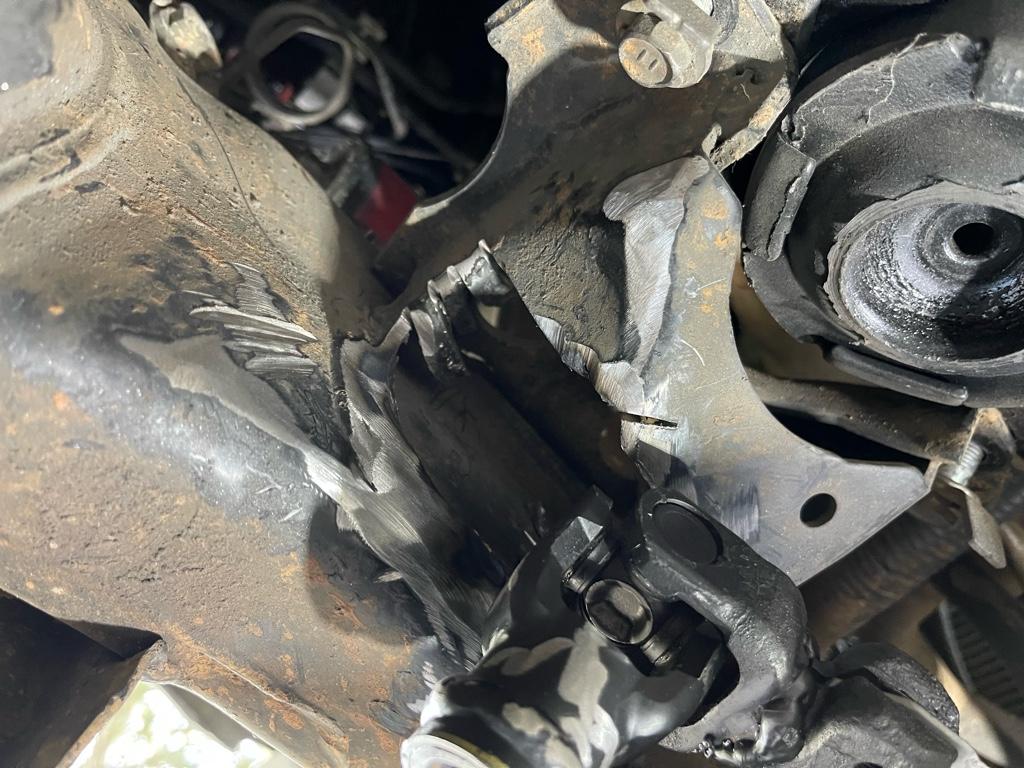
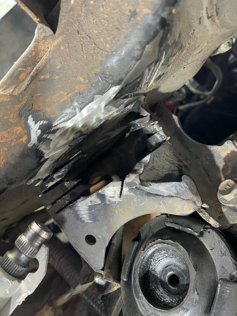
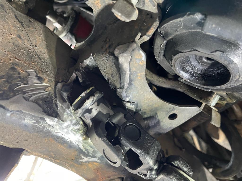
Damn, Not lookin forward to the steering shaft fix.

DocME in the FJ forum has a pic of his patch for the MM clearance, if you haven't already seen it.

Maybe he has a couple tips...

Just curious, you have a body lift on your Runner?


I do, 1.5 inches I believe and yea o saw his pics that’s what prompted me to don mine .. I’m guessing you haven’t fitted your steering shaft yet ?


Sent from my iPhone using Tapatalk
 
15 minutes of work and it’s starting to look like something.. too tired to do anything with it but I think it has a chance
a5a97f7b226bf5681dbc493bb254b3f9.jpg

ddc901fe359bdaffa5998333562ed254.jpg

9f1c411d91979ac5e1f6cb3f5ffa344d.jpg

059d6d44488fef404a606bf009759df9.jpg

29e578bb260a89c03f856436aa502667.jpg

567f1797954e676dbc07b9b5f274e971.jpg


Sent from my iPhone using Tapatalk
 
I’m guessing you haven’t fitted your steering shaft yet ?


Sent from my iPhone using Tapatalk
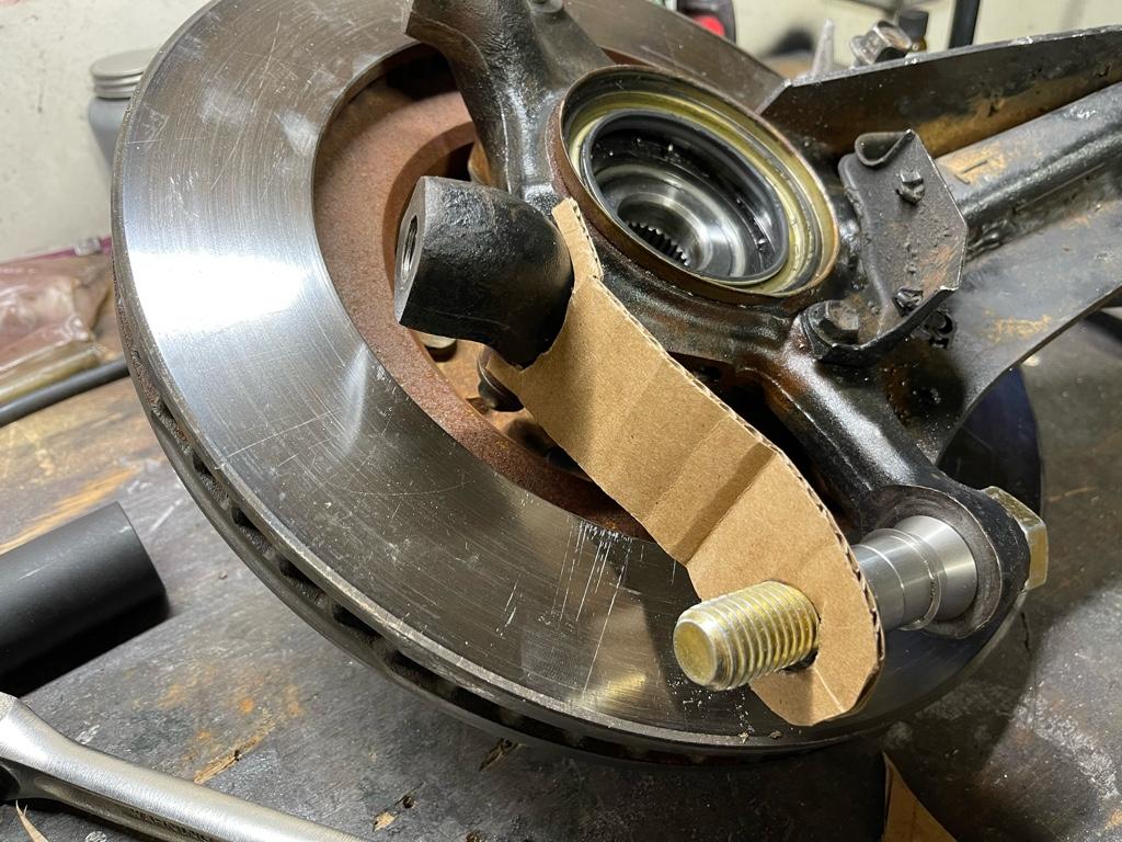
Just for a quick test fit, enough to know it's probably not going to clear. Wondering if the body lift (1" on mine) creates an angle that affects the clearance.

I think if you mock everything up, you can probably mount the rack further back, and get it to clear the MM, but the tie rod may contact the CO.

And ung ugh ... the 200 rack mod aint no joke.

On a positive note, the Double shear templates lookin good!
 
Last edited:
Just for a quick test fit, enough to know it's probably not going to clear. Wondering if the body lift (1" on mine) creates an angle that affects the clearance.

I think if you mock everything up, you can probably mount the rack further back, and get it to clear the MM, but the tie rod may contact the CO.

And ung ugh ... the 200 rack mod aint no joke.

On a positive note, the Double shear templates lookin good!


I don’t see a way to clear the mount by pushing the rack back, it’s very minimal that it could move back and the risk of hitting the coil over is not something I’m willing to take. Modifying the steering shaft is certainly a ton easier I feel like (plus I already started :rofl: :rofl:)

Thanks in the double shear ! Hoping to make a few adjustments to the board tomorrow and do a test cut with the plasma torch.


Sent from my iPhone using Tapatalk
 
Last edited:
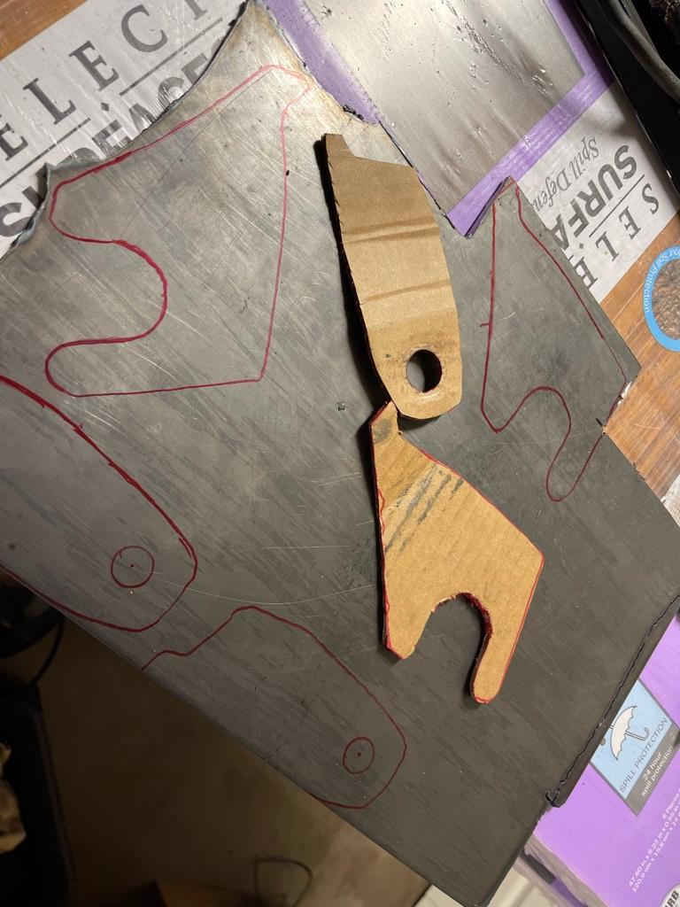
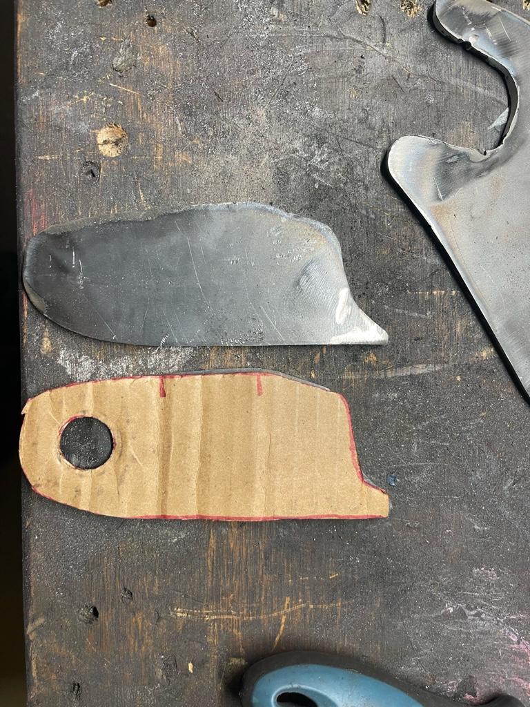
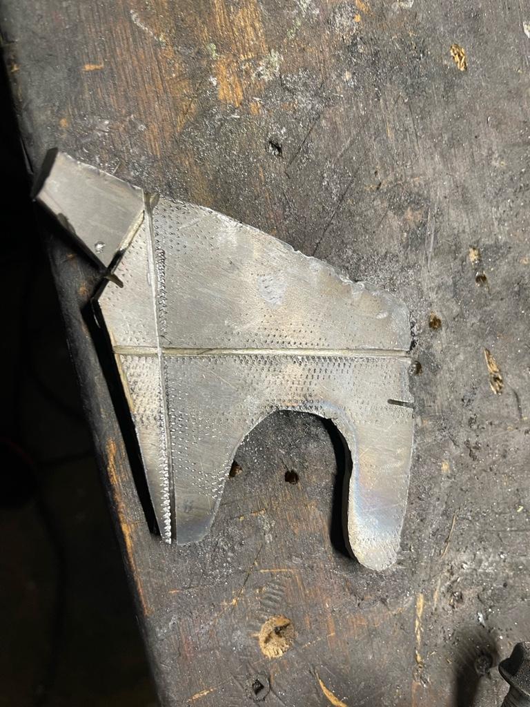
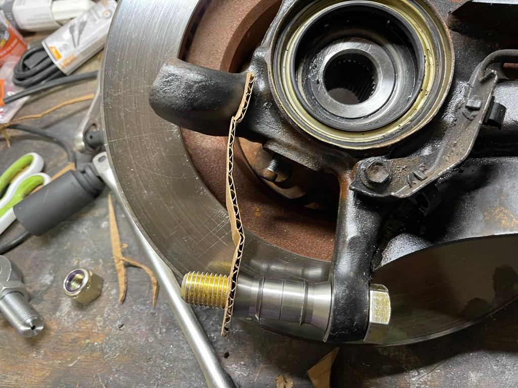
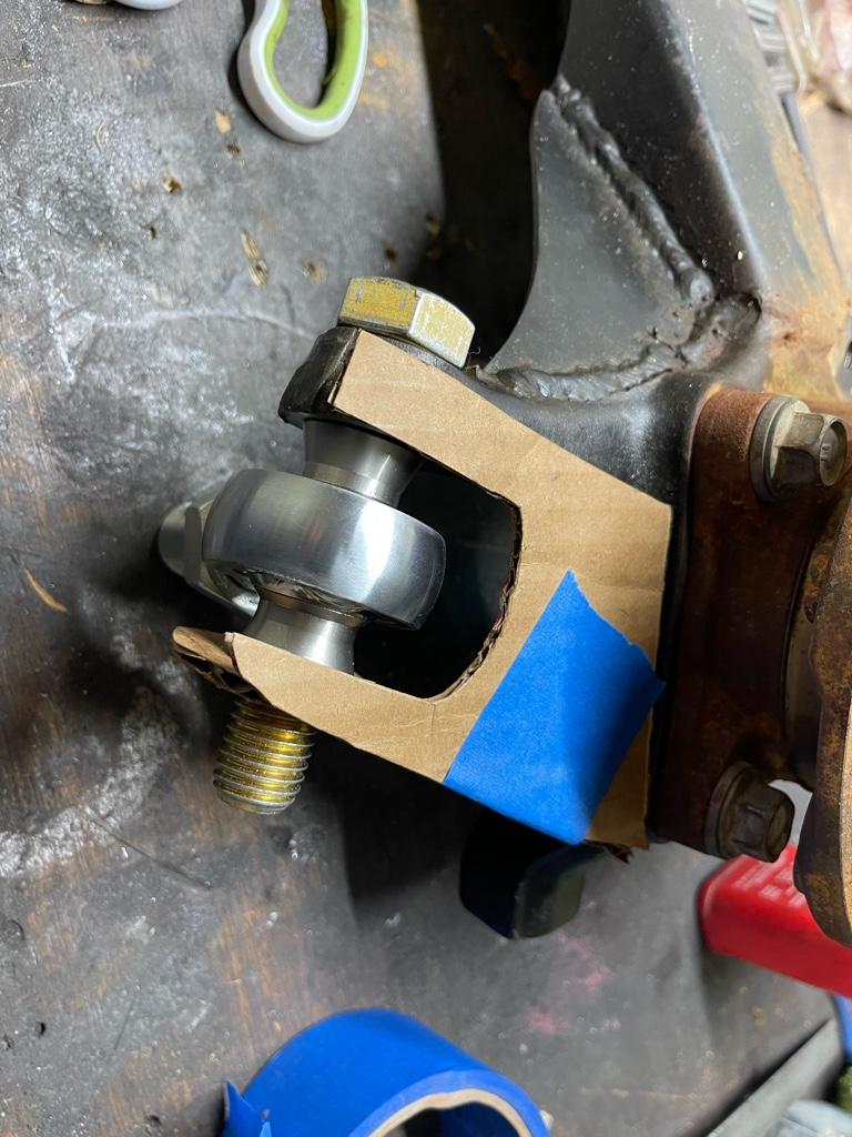
Template 3.0 should be fairly close.. I think it’s as close as I can get flimsy cardboard. Got them laid out on my flat sheet and will attempt the first set later today. At first I thought too thick.. but just so happens to be the exact thickness of my cardboard template so should work out ok. The bends should be fairly simple… one on the vertical plate and two on the horizontal.. tempted to use the plasma on these and clean up with the flap disk.. but I’m pretty terrible at freehanding the torch so we’ll see.. may end up just making more messy noise with the cutoff wheel instead .
52d439bf5004bd72435e6fca7be1b3b7.jpg

7a5e548f9d0929a874a18f6f9f6d2509.jpg

c71b2bbc030d7a4ffe8f9106896f9d53.jpg

bdca2706bc5538f2ca6e5fc1f4efecf1.jpg


Sent from my iPhone using Tapatalk
 
$400 isn’t sounding so bad right now … haha

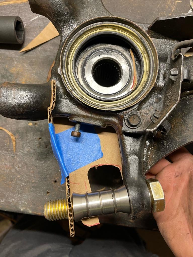
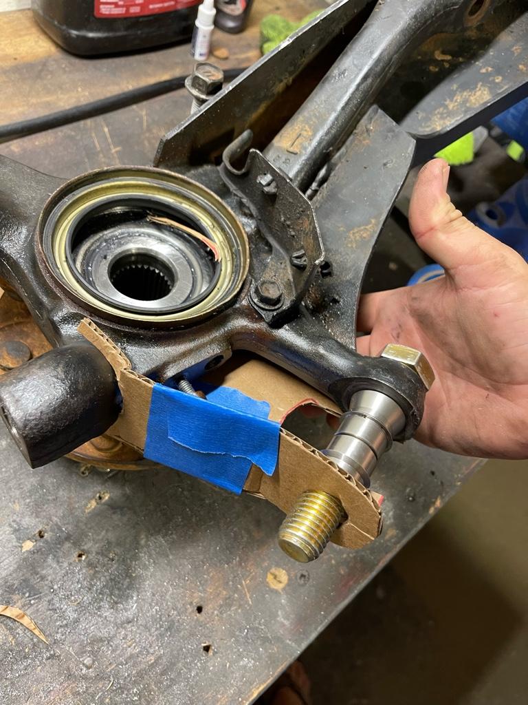
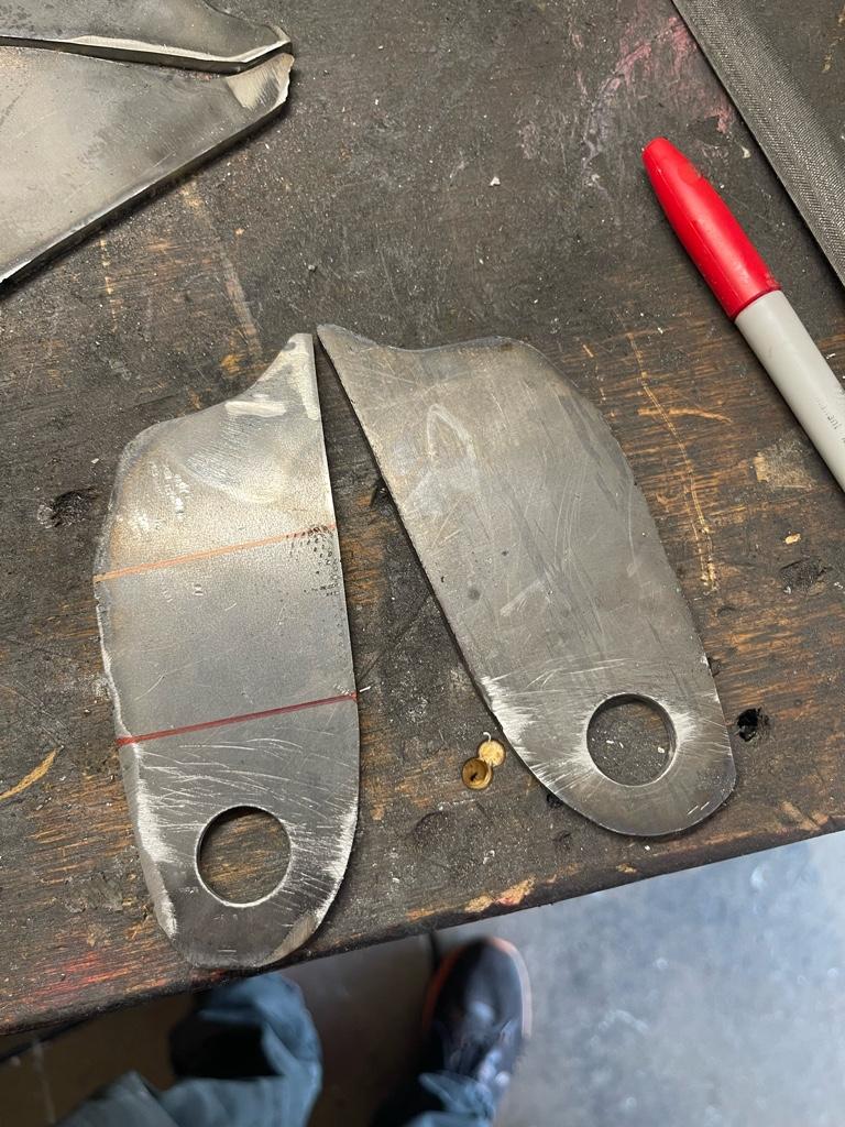
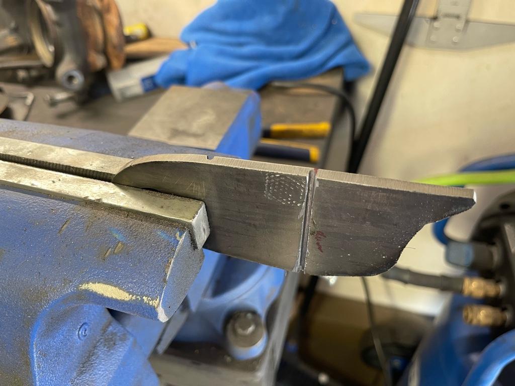
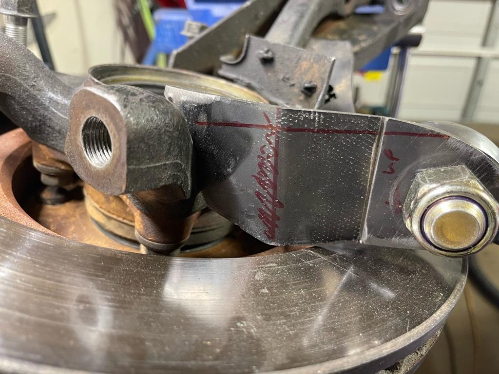
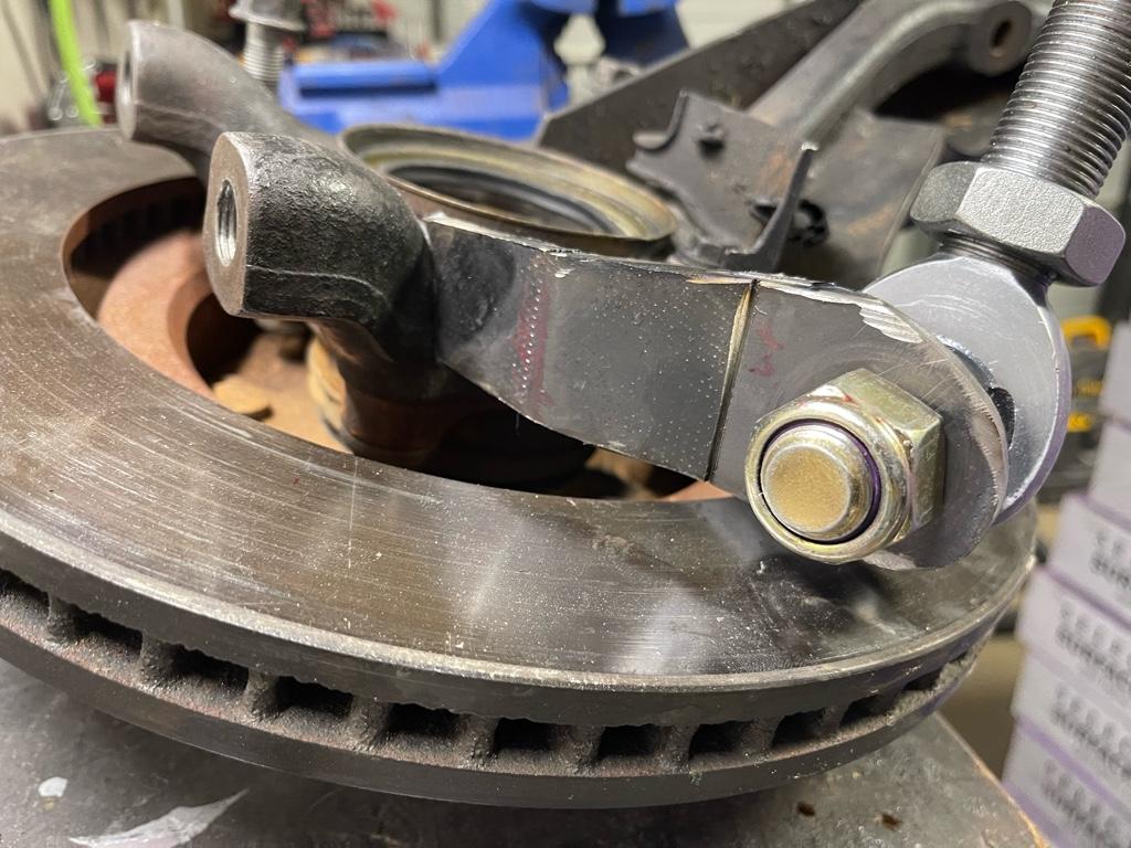
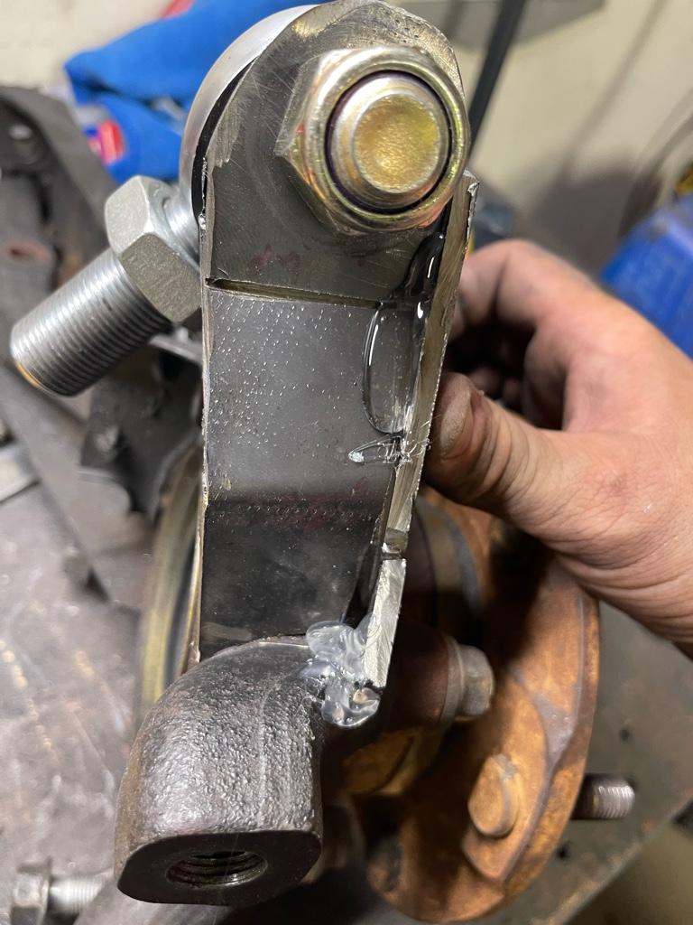
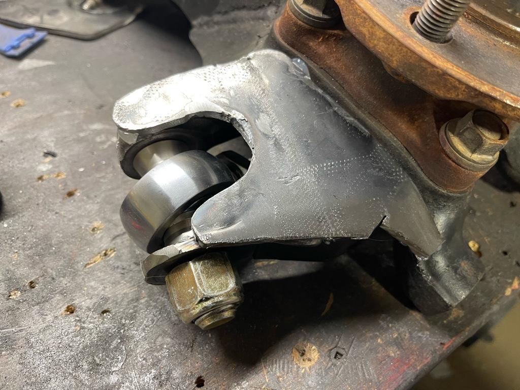
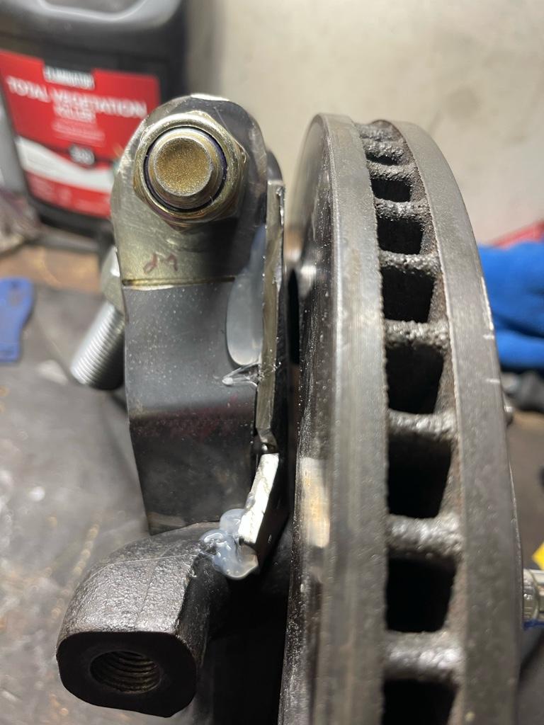
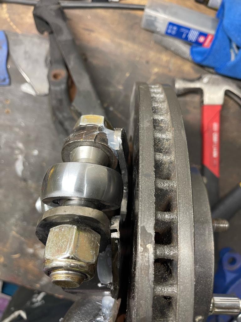
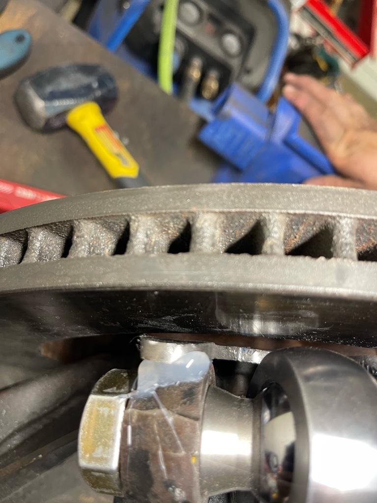
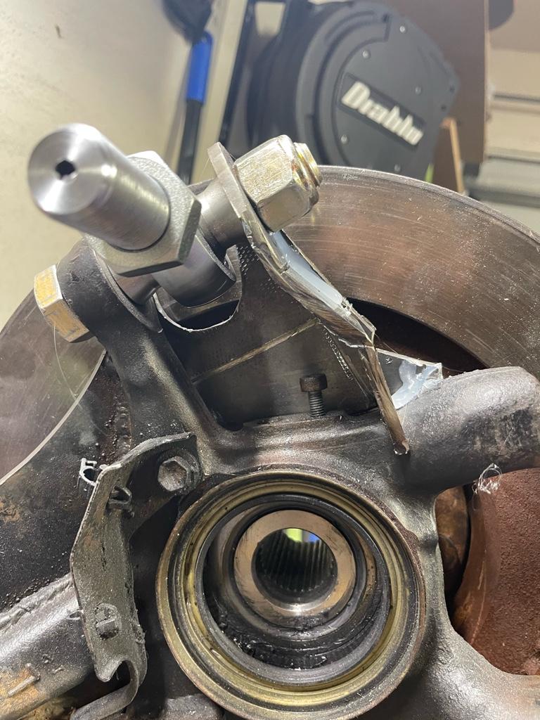
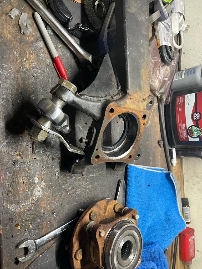
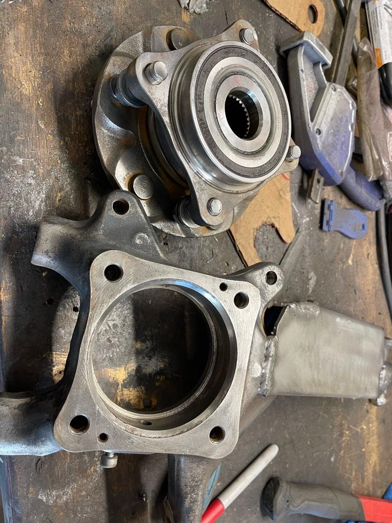
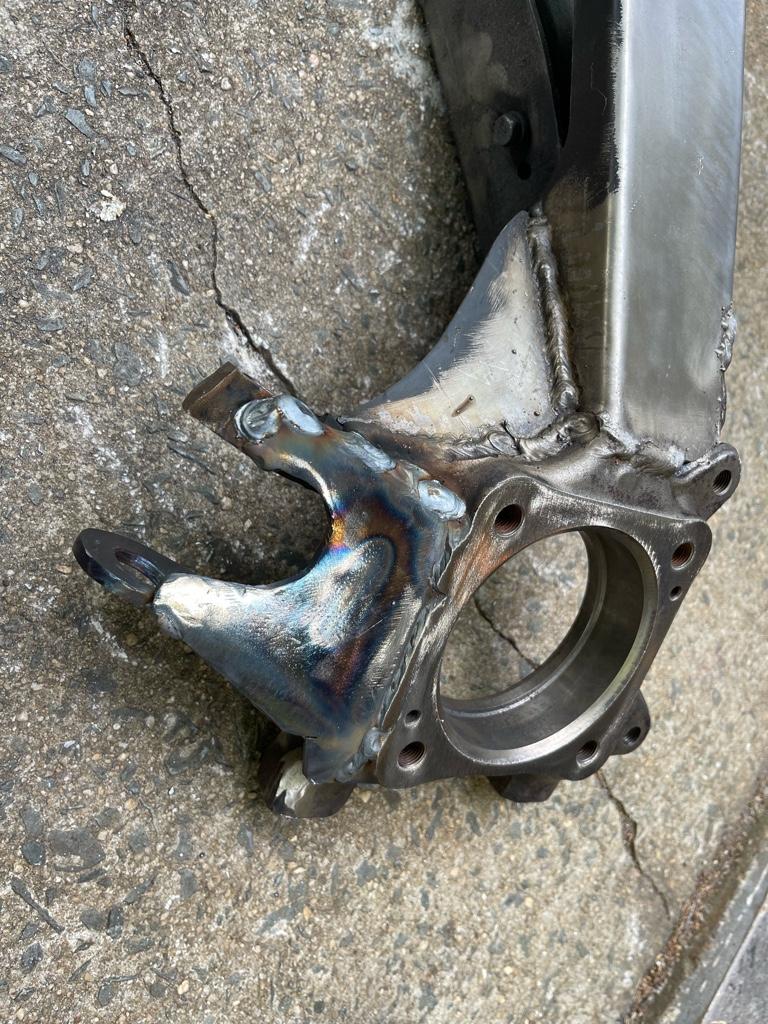
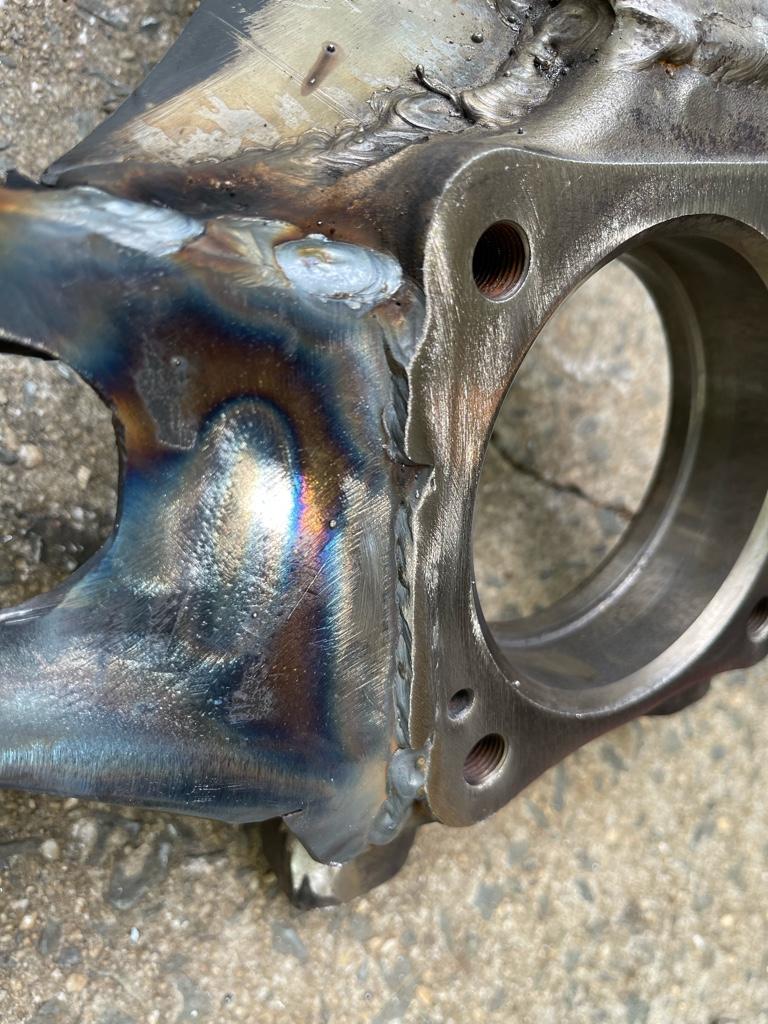
I’m a few hours into this now but making progress. The first round at the metal template cutout didn’t workout due to interference to the rotor, some pretty sever interference. So I had to trim down the brackets and beat them into shape. Using hot glue I got it to sit in place and I think it’ll clear everything. Unfortunately I don’t have the sensor with me to make sure it also fits.. but worst case I’ll just blow a hole into the side bracket for clearance. This should do OK as long as I really burn this bracket into the spindle.

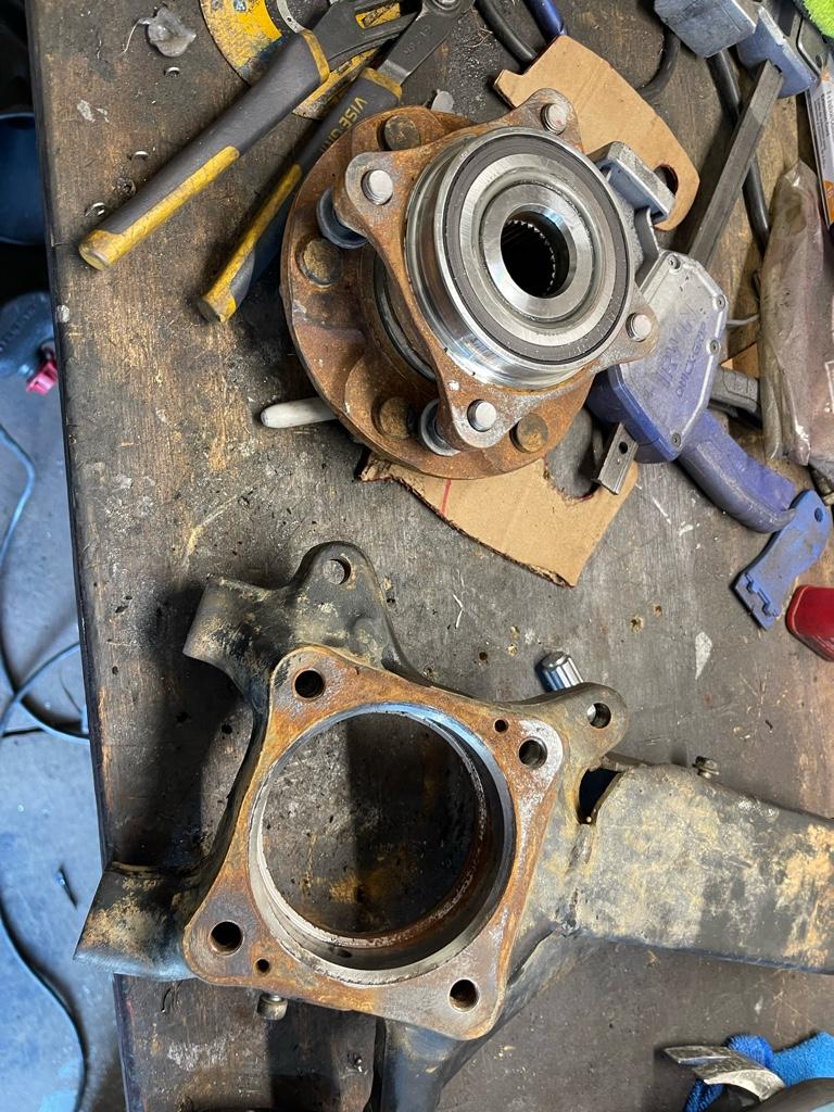
Had to pull the bearing so I can weld these later, but probably would have anyway to clean up all this surface rust and give it a fresh coat of paint before putting it all back together. Going to tackle the second side tomorrow and see how close I can get it replicated.

8b2b4992e063e8f25cd3d662ad3c983f.jpg

f0ed5f5b73962f3980cbcbbab6c819d6.jpg

180d384cb40a198aaf6390b403745ff8.jpg

00c7589601619de86a3e911d3e2fc242.jpg

43c0906127f51f74f91036ad00c73dda.jpg

1e406f1e3540cd52bd8438618fb863f8.jpg

9a0865d7ac828e0845a258c12fdfedcc.jpg

568227f67ad3ba805649cd1e12395024.jpg

14452bb671720e8b2bd84b6810baee57.jpg


Sent from my iPhone using Tapatalk
 
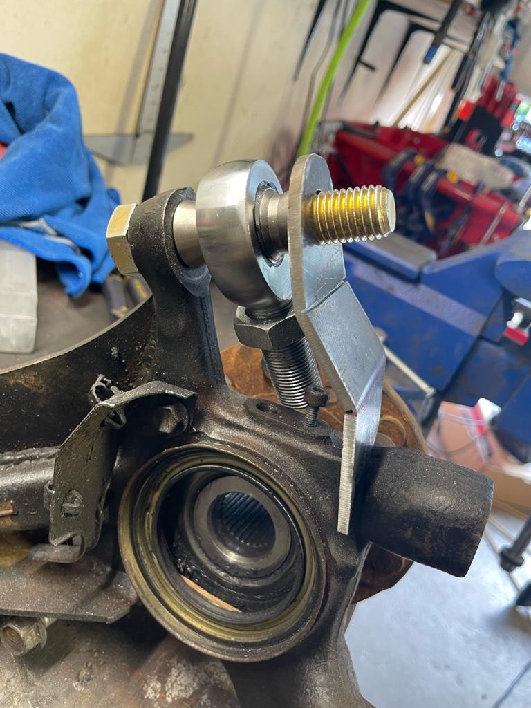
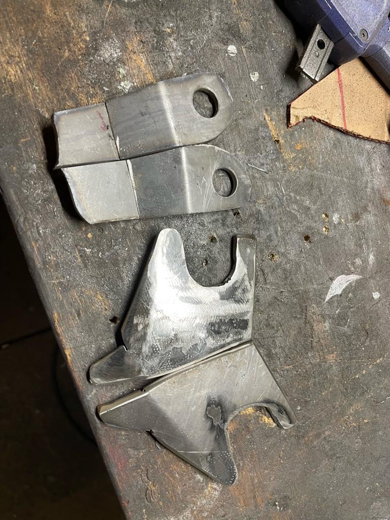
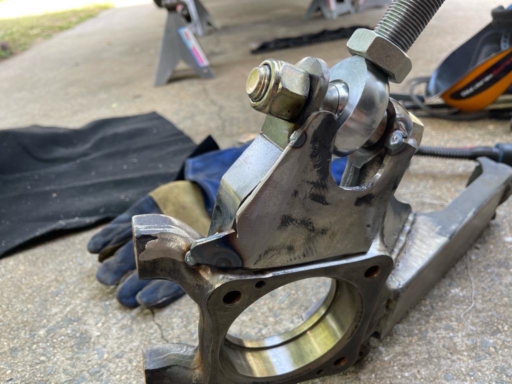
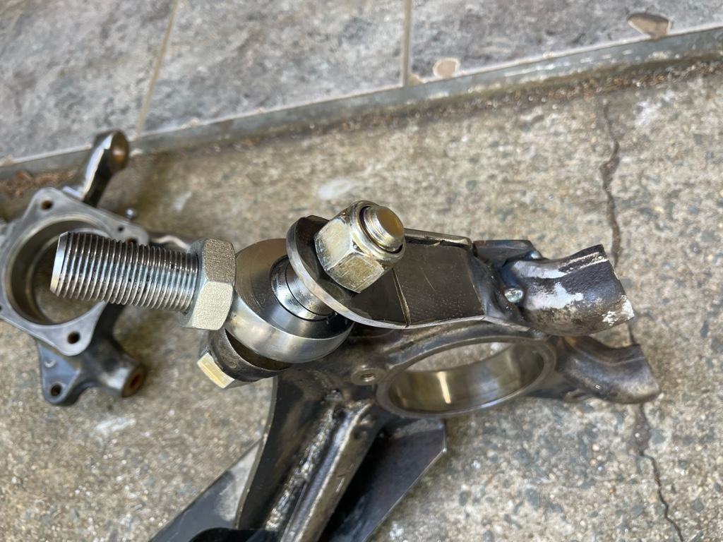
I was just browsing my pictures from the double-shear brackets Im making and something about how unprofessional it looks bothers me lol. I will definitely take the cutoff wheel and flap disk to it ahead of welding this bad boy on this week. Comparing the my pictures to the purchasable kit I see where some of my difference came out.. my bracket runs just about to the top of the original pivot arm, their bracket stop about mid way and is a bit shorter. The bottom bracket they have also ties in closer to the sensor mount, but I elected to make mine as low as possible since I have clearance to the rotor and it doesn't hurt anything but does give me a bit more wiggle room inside to weld and mount the sensor.


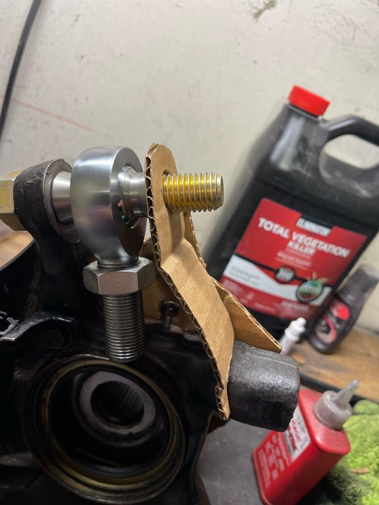
One thing I noticed is that I have full clearance to bottom out the heim upwards (so as if the suspension was fully drooped) but when I try to bottom it out downward (in extreme uptravel scenario) the lock nut on the heim impacts the lower bracket. It gets worse as it turn out.

I was originally going to clearance the bracket for this, but then realized that at ride height, the tie rods sit pointing down quite significantly, which leads me to believe that my up travel will run out of room a lot sooner than my heim will, so I should be in the clear, no pun intended :rofl:
 
I was just browsing my pictures from the double-shear brackets Im making and something about how unprofessional it looks bothers me lol. I will definitely take the cutoff wheel and flap disk to it ahead of welding this bad boy on this week. Comparing the my pictures to the purchasable kit I see where some of my difference came out.. my bracket runs just about to the top of the original pivot arm, their bracket stop about mid way and is a bit shorter. The bottom bracket they have also ties in closer to the sensor mount, but I elected to make mine as low as possible since I have clearance to the rotor and it doesn't hurt anything but does give me a bit more wiggle room inside to weld and mount the sensor.


One thing I noticed is that I have full clearance to bottom out the heim upwards (so as if the suspension was fully drooped) but when I try to bottom it out downward (in extreme uptravel scenario) the lock nut on the heim impacts the lower bracket. It gets worse as it turn out.

I was originally going to clearance the bracket for this, but then realized that at ride height, the tie rods sit pointing down quite significantly, which leads me to believe that my up travel will run out of room a lot sooner than my heim will, so I should be in the clear, no pun intended :rofl:

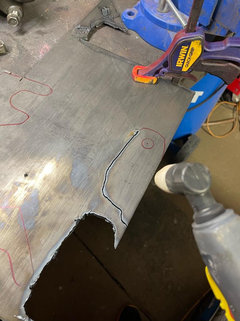
The plasma cutter is really hard to have a steady hand, which I think makes my parts look all wiggly. What I like to do is cut a template it of MDF on a woodworking bandsaw that accounts for the tip to follower distance. Then clamp and trace it with the plasma. Takes extra time, but makes it a tad neater
 
The plasma cutter is really hard to have a steady hand, which I think makes my parts look all wiggly. What I like to do is cut a template it of MDF on a woodworking bandsaw that accounts for the tip to follower distance. Then clamp and trace it with the plasma. Takes extra time, but makes it a tad neater

That is a great idea.. i'll have to keep that in mind. Also a good excuse to acquire a bandsaw... lol.

What I have been doing is cutting my parts slightly larger (following the tip just to the outside of my outline) and then using a 40-60 grit flap disk to do the final metal shaping. This is especially helpful when I want matching parts.. I just clamp them together and grind them both down to the necessary shape. Not perfect by any means.. but at least it results and pretty similar parts at the end.

One of my biggest hurdles in doing any sort of fab work is not really having a place to do it properly.. i have a "2 car" garage that only fits 1 car and is super limited on space.. my Supra is what sits there.. and when doing all this metal work I end up caking it in metal dust... which typically requires a VERY in depth detailing after any larger project. It would be nice to pull it out... but seeing how it is on jackstands with some work happening that is a no-go lol.
 
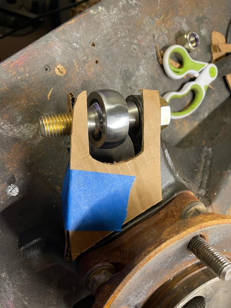
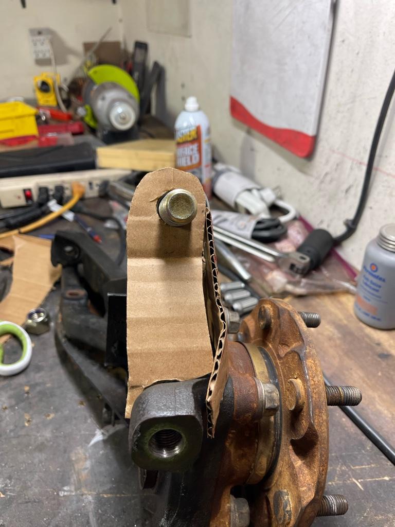
Well.. I think this is as far as I’ll get until I can weld these up tomorrow.. should be close from what I can tell but who knows. I’ll throw some tape on these to pull templates before I weld them up for those interested to DIY these… no promises that it’ll work but should at least be a good starting point.

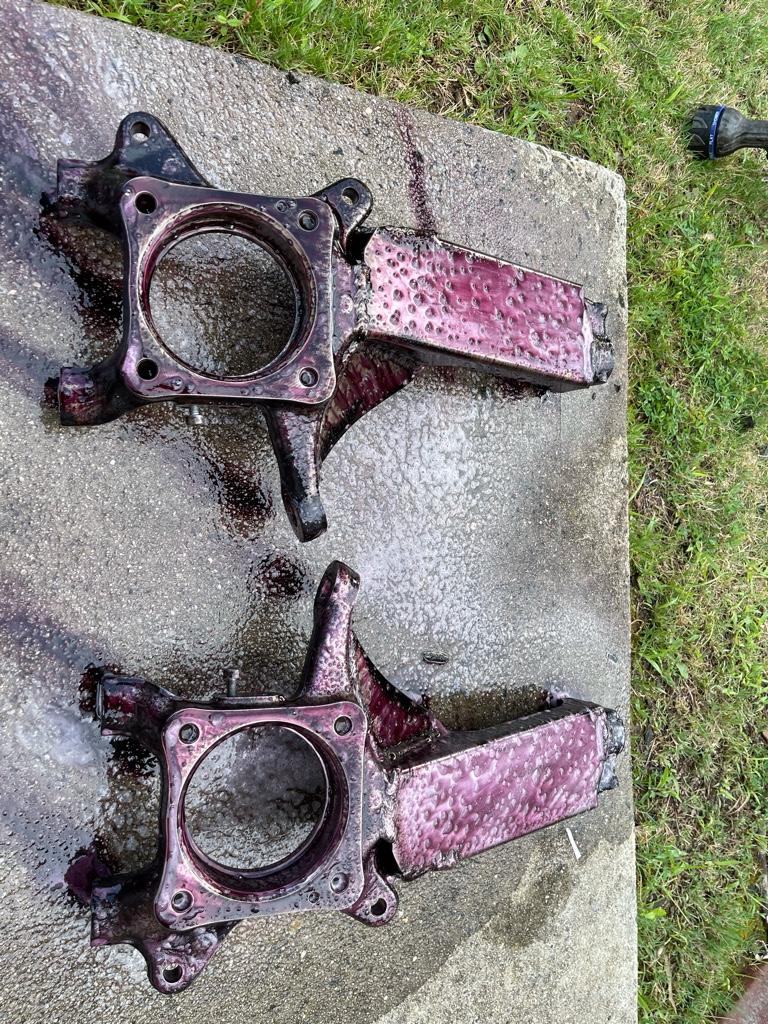
So much surface rust… spent a good hour with a wire wheel.. not perfect but significantly improved. I have some more Steelit coming Friday since I didn’t like how the paint held up with these spindles from last time. What’s a project budget ? If you find out what that means please let me know.. lol.

Getting anxious to get this welded on and test fitted.. last night hurdle should be the steering shaft so we’ll see if my mods will work. Fingers crossed.

9bb5918c186eabfefe47ff7f38e7aeed.jpg

b51ce9cc2a33ee169b58da8cb63e7240.jpg

4aad143bc16b83c26f6cd420aafe5464.jpg

a33041f2b121531b1ad1be9513d5bfe2.jpg

472db40eeadaf97620c6cb9d3938b59c.jpg


Sent from my iPhone using Tapatalk
 
One of my biggest hurdles in doing any sort of fab work is not really having a place to do it properly.

The fab work on my projects is always limited by space and tools. Mostly lack of know how, but a single car garage is pretty tight.

This latest project is too involved, so its in the driveway, and that presents its own set of draw backs.

When I get enough time to work on it again, Florida's rainy season will be in full swing. Then Hurricane season not far behind lol.

I would kill for a 2 bay and a lift. Anyone need some contract work done?
 
Well.. I think this is as far as I’ll get until I can weld these up tomorrow.. should be close from what I can tell but who knows. I’ll throw some tape on these to pull templates before I weld them up for those interested to DIY these… no promises that it’ll work but should at least be a good starting point.

So much surface rust… spent a good hour with a wire wheel.. not perfect but significantly improved. I have some more Steelit coming Friday since I didn’t like how the paint held up with these spindles from last time. What’s a project budget ? If you find out what that means please let me know.. lol.

Getting anxious to get this welded on and test fitted.. last night hurdle should be the steering shaft so we’ll see if my mods will work. Fingers crossed.

9bb5918c186eabfefe47ff7f38e7aeed.jpg

b51ce9cc2a33ee169b58da8cb63e7240.jpg

4aad143bc16b83c26f6cd420aafe5464.jpg
k
a33041f2b121531b1ad1be9513d5bfe2.jpg

472db40eeadaf97620c6cb9d3938b59c.jpg


Sent from my iPhone using Tapatalk

You probably know this already, but be careful getting those bad boys too hot.
 
You probably know this already, but be careful getting those bad boys too hot.


Yea.. definitely not ideal welding cast but certainly doable, the gussets I welded on last year seem to have held up decently. So we’ll see, fingers crossed haha


Sent from my iPhone using Tapatalk
 
I dream of having a barndominium style house lol. Like 80% garage, 20% house.

I do all my fabrication in my parents driveway and its tough having to get everything out to then turn around and pack everything up at the end of the weekend. At least we're all struggling together with lack of space hahaha
 
Last edited:
I dream of having a barndominium style house lol. Like 80% garage, 20% house.

I do all my fabrication in my parents driveway and its tough having to get everything out to then turn around and pack everything up at the end of the weekend. At least we're all struggling together with lack of space hahaha

I do the same thing for the big fabrication projects since the welder is at my parents place.. I try to pre-fab as much as I can at home because it is super frustrating not having your own tools around, and even more frustrating trying to pack what I need tool-wise from the house and take over there. It's only 15 minutes away.. but if you forget something and realize it in the middle of a project its super annoying to lose an hour to stop and go get it lol. And yea.. I'm then having to clean up and make sure I get all the junk out of the way. Luckily they don't mind too much (I don't think lol).

Ideally, when my wife and I build a house, what I want is a separate workshop/garage in the back. It doesn't need to be big or fancy, just enough to house a lift, have a place for all the tools, and a separate little area for fab work so that I don't have to worry about caking everything in the magic steel dust. This way I don't have to dirty up the actual garage for the daily cars.. It's pretty sad.. but I need a nice garage so much that it is actually the single reason we would move out of the house we're in now.. lol. Everything else is pretty awesome lol
 
Last night as we were walking the dogs I had a pretty big realization... my next door neighbor has a later model 4th gen silver 4runner that is bone stock. 06-09 model (those are the years..right.>?).. With my rig not at the house something about his rear fender flares caught my attention.. and the closer I looked the more I realized that they were significantly different from the 03-05 models lol. Who would have known??

I did some internet searching and it looks like they definitely restyled them quite a bit. The body line no longer goes horizontally across, but rather follows the arch around, and looks pretty damn good.

I may be wrong here.. but they also look significantly more bubbly then the more flat 03-05 variant. The fronts are different as well, but I didnt' care as much since my entire front end is swapped, but the rears really caught my eye... made me wonder if I would have ever taken on the hours of building my own wider flares if that is what I started with.. lol. Can anyone confirm whether or not they are actually a bit wider?? The interface between the horizontal flare to the rear bumper is also changed.. so yea, even if I wanted to tackle the wider flares as an option for other it would certainly only apply to the 03-05 models lol
 
I am also here to bi** about not enough garage space.... But if I had a larger garage I would probably be broke with all the vehicles I would collect and be in the same predicament.

From what I remember seeing online, the 06-09 flares are indeed wider. Though I doubt easy to graft onto an older 4Runner.
 
Can anyone confirm whether or not they are actually a bit wider??

The bottom edge of my rear fender flares (center of the flare, just above rear tire on a 2008) measure 2.75" deep. No idea how that compares to pre-2006s, but there's an input to go off of if you're curious.
 
A little more progress.. a bit more fab left before I start throwing it al together .. I’ll update some details in a bit

e14cc4e73af883ac101b47491f679569.jpg

04332573b9f55c3a3e8d0fcc19173b94.jpg

bbad0ee44e7ebee6c5fb33e507dc3ace.jpg

27c16206d401f35ab1f35ffc7c731738.jpg

3badfc407cf27055b4a6aae45f79979e.jpg

b2716adda0b5a3e0e240ae79f8f7ff50.jpg

aa7f7c8f3bba31a9bc624b9bd9925afa.jpg

26514ad735c151e656d6502077b93088.jpg


Sent from my iPhone using Tapatalk
 

Members online

No members online now.

Forum statistics

Threads
278,312
Messages
3,554,083
Members
248,016
Latest member
Advally Service

Trending content

Back
Top