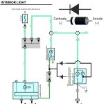
Another Map Lights with Dome Lights 2002 Model

If you are seeing that operation at the relay, it means the sim is doing its job. The relay coil is also an inductor, and will continue to try to pull current through the coil when door entry signal switch is opened. Most automotive relays have a diode or resistor snubber in them to reduce this effect. You can also do it externally with a diode or resistor. The dome light bulb will also do it if it is an incandescent. This is not an effect you will see in real life though (just something you have to be aware of to keep sensitive circuitry safe in some/many cases).

The power for the relay now will act a bit odd - when the map 2 switch is turned on, it will turn off the map 1 light if the dome light is on. And in this configuration, you will need diodes.

I had made the (incorrect) assumption that the map light switches had the pole towards the lights and the NO and NC connections towards the power. From your earlier descriptions, I should have been able to figure it out.

If the map light switches are 'reversed' (power in and out connections reversed) and the power for the relay is moved to 'constant', then you can connect the output to the unused (NC) map light switch connections and you won't need the diodes.

-Charlie

Based on the diagram I posted, diodes were required on the new power wires from the relay to each map light.

Are you saying that the relay acting as an inductor shouldn't pose a problem and the circuit will work like I expect? The sim threw me off.

Here's a picture of what the map light switch actually looks like. Center (grey) is common and that wire is pinned to the L-Y constant 12V wire in the factory connector. The yellow wire goes to the first map light bulb. As you can see the third pin on the switch is not used. When that map light switch is switched "off" in factory config the unused pin gets the constant 12V. I intended to use that pin as the +12V source on the relay and that's how I have it shown in the diagram.
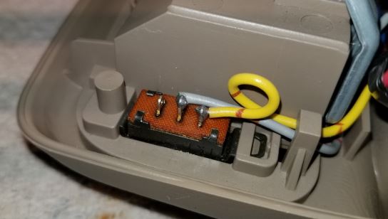
map_switch.jpg


If the relay acting as an inductor isn't a problem, I think I'm golden?

[MENTION=116195]weekendclimber[/MENTION], the way you have the diagram matches what I have in mine, only use used one diode. I think you actually need one for each lamp.
 
[MENTION=116195]weekendclimber[/MENTION], the way you have the diagram matches what I have in mine, only I used one diode. I think you actually need one for each lamp.

That's correct. My diagram is lazy, because hey it's the internet you're supposed to be lazy #okayboomer
 
Based on the diagram I posted, diodes were required on the new power wires from the relay to each map light.

Are you saying that the relay acting as an inductor shouldn't pose a problem and the circuit will work like I expect? The sim threw me off.

Here's a picture of what the map light switch actually looks like. Center (grey) is common and that wire is pinned to the L-Y constant 12V wire in the factory connector. The yellow wire goes to the first map light bulb. As you can see the third pin on the switch is not used. When that map light switch is switched "off" in factory config the unused pin gets the constant 12V. I intended to use that pin as the +12V source on the relay and that's how I have it shown in the diagram.

map_switch.jpg


If the relay acting as an inductor isn't a problem, I think I'm golden?

[MENTION=116195]weekendclimber[/MENTION], the way you have the diagram matches what I have in mine, only use used one diode. I think you actually need one for each lamp.
Your diode setup is right for the current configuration.

The relay will work fine in the configuration shown.

Just note that turning on map light 2 will turn off map light 1 when the door is open. The reverse isn't true (map light 1 has no effect on map light 2). If you power the relay from the constant voltage connection, that won't happen.

-Charlie
 
Your diode setup is right for the current configuration.

The relay will work fine in the configuration shown.

Just note that turning on map light 2 will turn off map light 1 when the door is open. The reverse isn't true (map light 1 has no effect on map light 2). If you power the relay from the constant voltage connection, that won't happen.

-Charlie

Thanks for confirming. That relay deal had me scratching my head.

I got ya on the map 2 on vs map 1 off. That's the intent. I'll make the final decision on that when I start to wire it up. Turned out easier than I expected.
[MENTION=116195]weekendclimber[/MENTION] LOL I hear ya, I knew what you meant haha.

Ordered the tiny 30A relay today, got two just in case :snacker:

Thanks guys!
 
Thanks for confirming. That relay deal had me scratching my head.

I got ya on the map 2 on vs map 1 off. That's the intent. I'll make the final decision on that when I start to wire it up. Turned out easier than I expected.

[MENTION=116195]weekendclimber[/MENTION] LOL I hear ya, I knew what you meant haha.

Ordered the tiny 30A relay today, got two just in case :snacker:

Thanks guys!

Can't wait for the video....you're doing a video right?!
 
Thanks for confirming. That relay deal had me scratching my head.

I got ya on the map 2 on vs map 1 off. That's the intent. I'll make the final decision on that when I start to wire it up. Turned out easier than I expected.

[MENTION=116195]weekendclimber[/MENTION] LOL I hear ya, I knew what you meant haha.

Ordered the tiny 30A relay today, got two just in case :snacker:

Thanks guys!

I'm too late to the party... This would be the ideal way to wire it in my mind... no relays needed. Both maps lights come on when a door is open, and still work independently when the doors are closed.

On the LG-B wire, it doesn't matter where you tap into it. You could tap the dome light switch and run a wire through the headliner, or I'm sure that wire runs through one of the footwells somewhere.

MSPaint for the win.

BTW - in the diagram before mine last posted, sorry to be critical, but you'll never be able to work the map lights independently, the relay would only need a jumper between 86 and 87 and a single tap to the L-Y wire or any +12V (no independent wires), nor would a diode be needed.
 

Attachments

  • Untitled.jpg
    Untitled.jpg
    97.2 KB · Views: 319
Last edited:
I'm too late to the party... This would be the ideal way to wire it in my mind... no relays needed. Both maps lights come on when a door is open, and still work independently when the doors are closed.
You missed the part where the map lights are wired opposite of the diagrams in sunroof 4Runners. So, swap pins 1 and 3 - then try your diagram again. That's why the relay is needed.

Your diagram will probably work just fine on the non-sunroof 4Runners... but would still have to be verified that the switch is on the ground side, not the power side of the circuit.

-Charlie
 
BTW - in the diagram before mine last posted, sorry to be critical, but you'll never be able to work the map lights independently, the relay would only need a jumper between 86 and 87 and a single tap to the L-Y wire or any +12V (no independent wires), nor would a diode be needed.

No offense taken, I was being lazy on the diagram for the map lights. I love the discussion here as I consider myself an amateur wiring person. See [MENTION=139000]phattyduck[/MENTION]'s comment regarding where the switch is (ground side vs power side), the last diagram I posted has them positioned correctly for the sunroof models. Your point for jumpering 86 and 87 to L-Y is an excellent one.
 
Last edited:
You missed the part where the map lights are wired opposite of the diagrams in sunroof 4Runners. So, swap pins 1 and 3 - then try your diagram again. That's why the relay is needed.

Your diagram will probably work just fine on the non-sunroof 4Runners... but would still have to be verified that the switch is on the ground side, not the power side of the circuit.

-Charlie

Dang, I did miss that. I'll check my FSM when I get home, but in the mean time I see two ideas - either dual diode isolate the map lights in your diagram, similar to how I had in my diagram (but for the correct polarity), or if possible, do what I did still and move the switch wires. I personally would skip adding extra relays / wires - I'm just a minimalist.
 
The relay is easy and the one I found is like 1/2" by 1/2" in size so tiny, shouldn't be an issue.

I was surprised to find the switch config when I took the map light down and started testing with the MM. It's almost like Toyota intended the map lights to work when the doors opened, but someone axed it (bean counter)?

I've decided to adjust it and move the 12V relay input to the constant 12V source so both map lights are on when the doors are opened. I thought I might wanna turn one off for some reason, but I don't ever see that happening.

Got the parts ordered. Thanks again for the input folks.
 

Members online

Forum statistics

Threads
278,309
Messages
3,554,071
Members
248,016
Latest member
Advally Service

Trending content

Back
Top