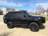
ANTMAN'S Thread

I replaced it with a 1000W inverter a few years ago- much better use of the space!

I did like it when I had it though- [MENTION=42734]Kraeken[/MENTION] has the same one in his though and last I heard he was loving it. Maybe he will chime in...

Sorry I haven't been around in a while, lots of stuff going on in my life. I still have the sub, it works great for my purposes. I replaced all of my speakers with Polk Audio, and it works well to compliment them. The only issue, and I forget the terminology, is when you raise the volume the sub and the speakers go up at slightly different levels, so depending on your speakers you may have to readjust the sub if you're blasting your music. It doesn't matter to me because the control is right at my hand and it adjust it for almost every song.
 
I have an almost identical setup even with the same switch. I'm trying to get my switch LEDs working like yours but having issues. I'm doing only two things differently:
<ol>
<li>I'm not soldering connections. Instead, I am using T-taps to dually connect what you have labeled as Ignition Only + (In) to the top left and the Auxiliary Battery + (In) to the bottom left terminal. The grounds are jumped using spade terminals.</li>

<li>I'm not using a small led to indicate that the batteries are connected via the solenoid.</li>
</ol>
My last question is, where am I supposed to ground the middle right terminal ("OFF")? I've tried both the main starting battery using long test leads and also tried using the solenoid's ground but no joy.

Here is a picture to get help understand:

antman_switch_wiring.jpg
 
I have an almost identical setup even with the same switch. I'm trying to get my switch LEDs working like yours but having issues. I'm doing only two things differently:
<ol>
<li>I'm not soldering connections. Instead, I am using T-taps to dually connect what you have labeled as Ignition Only + (In) to the top left and the Auxiliary Battery + (In) to the bottom left terminal. The grounds are jumped using spade terminals.</li>

<li>I'm not using a small led to indicate that the batteries are connected via the solenoid.</li>
</ol>
My last question is, where am I supposed to ground the middle right terminal ("OFF")? I've tried both the main starting battery using long test leads and also tried using the solenoid's ground but no joy.

Here is a picture to get help understand:

antman_switch_wiring.jpg

Got your PM and responded...Pic is too small to be useful.
 
My Storage box

I followed Antmans , with a few modifications. The latches for the two doors came out of a 90s Durango and the lid supports came from Home Depot at $2.79 each.
 
Antman

Thought...

On the independent fog light mod ( on when you want with; ing on; stay on with hi beams )

Factory relay being a ground interrupted relay/ or possible the can buss doing that
Fog light relay ( under hood) ground activated relay

Its my understanding (stock):
1) ignition off FLS off
factory relay is open so twin wires to FLS is open ( neither ground or + for the non electrical owners)
2) ignition on FLS off headlights off
factory relay is open so twin wires to FLS is open
3) ignition on headlight switch on (in low beam position)
factory relay is closed feeding ground to the fog light switch ( on the non-switched side of the FLS )
4) ignition on headlight switch on and in hibeam position
factory relay opens interrupting the ground feed to the non switched side of the FLS and therefor turning off the fog lights


So a possible another way to have FL on all time ( when ignition on/head light switch at least in parking light position)

new relay activated by switched ignition power; controlling signal ground to non switched side of FLR
86 switched ign power
85 ground
30 ground
87 switched ground to non switched side of FLS t-taped in non cutting


Or
FL on with headlights on but on both low beam and hi beam

New relay activated by switched 12+ with headlights; controlling ground to non switched side of FLR
86 +12V with headlights/parking lights on
85 ground
30 ground
87 switched ground to non switched side of FLS t-taped in

with can bus being involved possible diode isolate the factory wire before the T-tap

wonder if those relay configurations above would keep the FL indicature lit on the dash ( at least maybe in the low beam position)
 
Antman

Thought...

On the independent fog light mod ( on when you want with; ing on; stay on with hi beams )

Factory relay being a ground interrupted relay/ or possible the can buss doing that
Fog light relay ( under hood) ground activated relay

Its my understanding (stock):
1) ignition off FLS off
factory relay is open so twin wires to FLS is open ( neither ground or + for the non electrical owners)
2) ignition on FLS off headlights off
factory relay is open so twin wires to FLS is open
3) ignition on headlight switch on (in low beam position)
factory relay is closed feeding ground to the fog light switch ( on the non-switched side of the FLS )
4) ignition on headlight switch on and in hibeam position
factory relay opens interrupting the ground feed to the non switched side of the FLS and therefor turning off the fog lights


So a possible another way to have FL on all time ( when ignition on/head light switch at least in parking light position)

new relay activated by switched ignition power; controlling signal ground to non switched side of FLR
86 switched ign power
85 ground
30 ground
87 switched ground to non switched side of FLS t-taped in non cutting


Or
FL on with headlights on but on both low beam and hi beam

New relay activated by switched 12+ with headlights; controlling ground to non switched side of FLR
86 +12V with headlights/parking lights on
85 ground
30 ground
87 switched ground to non switched side of FLS t-taped in

with can bus being involved possible diode isolate the factory wire before the T-tap

wonder if those relay configurations above would keep the FL indicature lit on the dash ( at least maybe in the low beam position)


Oh.....ok?!

Go ahead and try it- I'm not even going to try to figure out what you wrote there, lol.

Everybody keeps trying to make it work. Mine lights up so I'm happy with it.

Good Luck there!
 
Oh.....ok?!

Go ahead and try it- I'm not even going to try to figure out what you wrote there, lol.

Everybody keeps trying to make it work. Mine lights up so I'm happy with it.

Good Luck there!

I was a stereo and alarm installer for many years so really its just a matter of me getting under the dash and testing with my test probe.<<< ooo that did not sound right :drum:

:loco:Crazy thing is i Don't even have my 2016 4runr yet waiting on it to be delivered...

Going to test some things out while im an already in there; working on wiring in the the 2 in 1 Led DLR/ fog lights.:boink::thumb:
 
I was a stereo and alarm installer for many years so really its just a matter of me getting under the dash and testing with my test probe.<<< ooo that did not sound right :drum:

:loco:Crazy thing is i Don't even have my 2016 4runr yet waiting on it to be delivered...

Going to test some things out while im an already in there; working on wiring in the the 2 in 1 Led DLR/ fog lights.:boink::thumb:

This mod would be easy if you could get to the relays, but realistically you can't. If I ever get my hands on a junkyard relay box from a 5th Gen I'll make it work the "right way". Until then, it is what it is.
 
Got your PM and responded...Pic is too small to be useful.

Very much appreiciate your response. I still am working on a bit better diagram for you to help you acaually help me. My car is in the shop now getting a front suspension squeak looked at so I'm not able to get a good photo. Here is a better photo of the same picture. Thanks again! You're one of the few it seems with a similar documented dual-battery setup. As I said in my PM there I tried grounding it via a long test lead to my starting battery

<a href='http://postimg.org/image/gd5vbn4dz/' target='_blank'><img src='http://s23.postimg.org/gd5vbn4dz/antman_switch_wiring.jpg' border='0' alt="antman switch wiring" /></a>
 
Man I miss Bubs...

I said goodbye to her favorite rock this morning for her...sure was sad...

Thanks for coming, I had a great time! ( I got blasted by a storm right after you texted me...holy fballs did rain and blow...stayed together though (whew)

Love ya man..you're the shit

Is that a new WHITE runner with an ARB front bumper? Didn't think they made those or did you modify the area by the lights?
 
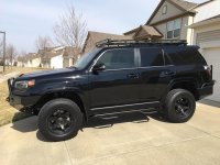
Gave The Beast a much deserved hand wash. Hats off to [MENTION=60893]Diver Deuce[/MENTION] as this is the first "Spring" after saltmageddon that I don't have to touch up my painted chrome grill...best $20 I've ever spent!

Anyway- still did a couple little mods today- nothing special, really.

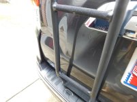
Put some grip tape on the bumper and ladder- long overdue for that. Speaking of the Gobi, it's starting to look a little rough from use. Lots of chips and surface rust and the powder coat is getting dull. I'm gonna take it off and paint it probably this summer.


DSCN0697.jpg


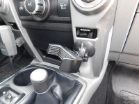
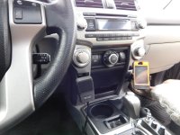
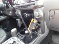
Also took a phone holder that wouldn't work in the space I wanted and swapped bases with my Garmin. I also screwed it in from behind the panel. The cam still works and pulls it nice and tight. Pretty happy with this.

.
.
.
.
.


DSCN0699.jpg

DSCN0701.jpg

DSCN0702.jpg
 

Attachments

  • DSCN0697.jpg
    DSCN0697.jpg
    126.3 KB · Views: 1,502
  • DSCN0699.jpg
    DSCN0699.jpg
    128.1 KB · Views: 1,525
  • DSCN0701.jpg
    DSCN0701.jpg
    125.8 KB · Views: 1,561
  • DSCN0702.jpg
    DSCN0702.jpg
    129.2 KB · Views: 1,555
Last edited:
I added grip tape to my sliders, since they're always wet due to the rain, but I think I'll do that on the ladder as well.
 
Thank You Antman!

Just wanted to thank you for your rocker cut. Followed most of your instruction but used a jigsaw instead of Cutoff wheel. The end result as you can see before and after looks like the 4runner went on a diet and way more stout. Also got the steps 4inches higher off the ground and removed the flimsy adapters. Again. Thanks.
 

Attachments

  • IMG_0691.jpg
    IMG_0691.jpg
    134.1 KB · Views: 1,364
  • IMG_0713.jpg
    IMG_0713.jpg
    132.5 KB · Views: 1,537
Trail Edition Skid Plate Swap


Today I added yet another TE piece to my SR5. [MENTION=49537]4ShoreRunner[/MENTION] gave me his old gas tank skid plate when he came to the Antman Garage last weekend for a fire-safety lesson...:boom: Thanks man!


Anyway- this skid is pretty much famous because it has seen lots of use- from Ouray to The Cove. I think it held up reasonably well for the trail duty it's seen. Lots of character! Overall, it's in good enough shape for me to make use of it with a little work.

I know, I know- I don't really offroad (maybe a little), but eventually I guarantee I will be scratching and denting this thing up (again!).

Here she is...


MOAB DIRT!!!!


SO- I sanded all the rust off and beat the skid back into submission with a 5lb hammer (it was dented quite a bit :) ) and then I sprayed a few coats of this:


I can't stress how great this stuff is. It's more like a durable plastic coating than paint. It has held up on my storage box extremely well. I love it!


Here's the skid after some work. It isn't perfect but it doesn't need to be. I just wanted to make sure it wouldn't rub the tank or rust any more.


A comparison between the SR5/LE skid plate and the Trail Edition skid...


For those that want to know- the factory skidplate removes completely from the gas tank with no need to lower the tank at all. There are separate bolts/straps holding the tank up.


There are 4 bolts holding the SR5 skid in place. 3 on the frame rail, and 1 up by the driveshaft for the front hanger. These all get re-used for the new skid.

The Trail Skid only requires 2 additional bolts for the rear hangers. Both are 12mm just like the other skid bolts.

These are the locations for the 2 additional bolts:

Rear frame rail ( the bolt with the "8" on it is securing the rear tank strap to the frame):


Rear crossmember:


Make sure you get ALL THE BOLTS started into their threaded holes before you tighten any, otherwise you could easily strip some threads.


I wanted to make note of one bolt that is a little hard to get to- behind the driveshaft. I originally tried to use an extension(s) unsuccessfully. Then I realized a short 12mm socket will fit behind the driveshaft easily...


One other note-

I once again used anti-sieze on all the bolts. No rusted fasteners!


Finished!


Oh yeah- I painted 2 more things before I retired the Rustoleum.

[MENTION=51186]philsey[/MENTION] - You can shut up now. :D


Happy Modding gentleman!

I know this is super old thread but I was wondering if you remember what you torqued those skid plate bolts too? I am installing a set of RCI skids and I am assuming all the skid plates torque to the same lbs. thanks.
 

Members online

No members online now.

Forum statistics

Threads
278,306
Messages
3,554,045
Members
248,016
Latest member
Advally Service

Trending content

Back
Top