Bootown's Thread

bootown

Member
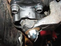
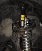
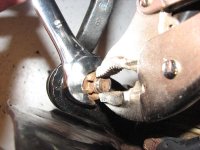
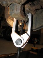
This post is more for me than it is for you, but if you like it too that's great. I don't like the T&D sticky at all and wanted quick, straight-forward access to my collection of links. If you don't yet know about lower ball joint or radiator failures you definitely want to do some research on those. There are write-ups in this thread for replacing both.

How to search t4r.org - site:toyota-4Runner.org/3rd-gen-t4rs/

4Runner Websites
Toyodiy – part numbers and write-ups for Toyota’s
when entering your vehicle info: VZN180 = 2WD, VZN185 = 4WD
Factory Service Manual – repair manual & electrical wiring diagrams
Toyota Reference – paint code & brochures
Yotatech
4Runners.org - lots of writeups
4x4wire
TTORA
Top4Runners
J.A.'s 4Runners


Repair, Maintenance, Mods
Scheduled Maintenance Intervals
3rd Gen FAQ - raydouble
Tutorial & Documentation Reference
List of mods

Engine
Oil Change
Oil Change - no drip
Oil Filter Relocation
Radiator - jbudhram015
Radiator - bootown
Coolant Flush
Spark Plugs - zcruiser
Spark Plugs - 4runners.org
Throttle Body & MAF
Throttle Body - JA
MAF - JA
Block Heater
Drive Belts
Timing Belt - toy4x4
Timing Belt - skjos
Timing Belt - autodiyonline
Timing Belt - nwtoys
Timing Belt - 4x4wire
Valve Covers
Valve Cover Gaskets - Jon
5VZ-FE Removal
Fuel Filter - 4runners.org
Fuel Filter - raydouble

Transmission
Transmission Cooler - BigFishAllDay
Transmission Cooler - Bob_98SR5
Transmission Cooler
Transmission Fluid Flush- skjos

Brakes
Brake Bleeding - JA
Brake Bleeding - GSGALLANT
Brake Bleeding - 4runners.org
Tundra Brake Upgrade - BigFishAllDay
Tundra Brake Upgrade - Ritzy4Runner

Suspension & Steering
Power Steering Flush - broncosi
Power Steering Flush - pdx650
Power Steering Flush - GSGALLANT
Steering Rack Guide
Steering Rack Bushings - raydouble
Steering Rack Bushings - 4x4wire
Steering Column Slip Joint
Inner Tie Rods
Inner & Outer Tie Rods
Lift Information
Lower Ball Joints - spongerx
Lower Ball Joints - bootown
Shock Bushings
Control Arms & Upper Ball Joints
Upper Ball Joints - ttora
Upper Ball Joints - yosh2000
Steering Knuckle
Front Springs w/o Spring Compressor
Coilovers & Rear Shocks/Coils - Toytec Lifts
Rear Shocks
Rear Coils

Transfer Case, Axles, Driveshaft
CV Axle - 4x4wire
CV Axle - nquaint
CV Axle Reboot
Differentials & Transfer Fluids
Transfer Indicator Switch
Transfer Case Seals
Driveshaft / Propeller Shaft Lubing - Nelsonmd
Driveshaft / Propeller Shaft Lubing - 4x4wire
Driveshaft / Propeller Shaft Lubing - 4runners.org
Driveshaft / Propeller Shaft Lubing - ih8mud
Rear Axle Seals - BigFishAllDay
Rear Axle Seals - dcrim1
Transfer Case Basics


Exhaust
Oxygen Sensor - 4runners.org
Oxygen Sensor - 4x4wire

Body
Front Bumper
Grille
Fender
Hood Scoop
LED Taillights

Electrical
Starter Contacts - CoMarc
Starter - HaveBlue
Starter - 98LimitedCustomized
Disable VSC & TRAC
Disable VSC & TRAC, ABS active
ABS/VSC/TRAC Links - Nelsonmd
Disable Daytime Running Lights
Gauge Cluster
Clock Repair
LED Interior Lighting (Sylvania Lighting Replacement Reference)
2002 LED Interior Light List
Antenna Mast
Antenna Motor
Transponder Key Programming
Wireless Transmitter Programming
Fog Lights
Keyless Chirp Adjustment
Field Monitor
Factory Stereo Auxiliary Input
HVAC bulbs
Front Seat Disassembly
Power Seat Track
Swap clock for outside temperature gauge
Alternator

Miscellaneous
Sound Deadening


Manufacturers / Retailers
4xInnovations
ARB
Budbuilt
Burtman Industries
Catoctin Jeep and Off Road
CBI Offroad
Denso
DiamondRax
Irbis Offroad
Lil' Skip's Offroad
Lotus Development
Outdoor Logic
Savage Offroad
Shrockworks
Sonoran Steel
Spidertrax
Total Chaos
Toytec
Trackdecal
Weathertech


Online Toyota Parts Dealer
<-- best online dealer out there (coming from someone that has spent thousands of dollars on parts from online Toyota dealers)
[URL="http://parts.camelbacktoyota.com/ "]Camelback Toyota
<-- these guys used to be good, but the new guy has a he knows it all attitude and gets pissed at customers over the phone and changes your order however he likes
Certifit (non-oem parts)

4th Gen Links
1GR-FE Spark Plugs
 
Last edited:
Register to hide this ad
WANT TO BUY
01-02 tail light wiring (bulb holders to the connection just behind cargo panels)


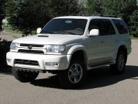
2002 Golden Pearl 4WD
IMG_3065_25.jpg~original

IMG_1349_25.jpg~original


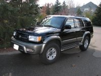
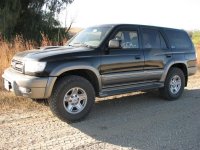
1999 Black Limited 4WD Locker
IMG_2432_25.jpg~original

IMG_3515_25.jpg~original
 

Attachments

  • IMG_1366_25.jpg
    IMG_1366_25.jpg
    68.9 KB · Views: 229
  • IMG_3067_25.jpg
    IMG_3067_25.jpg
    78.9 KB · Views: 220
  • IMG_2432_25.jpg
    IMG_2432_25.jpg
    83.9 KB · Views: 226
  • IMG_3515_25.jpg
    IMG_3515_25.jpg
    79.6 KB · Views: 219
  • IMG_2410_25.jpg
    IMG_2410_25.jpg
    50.1 KB · Views: 228
Last edited:
Front Power Seat Removal & Disassembly


****Use this guide at your own risk and double-check everything - procedure and specifications. The factory service manual can be a great help.****

This information may be useful if you want to:
- Remove front seats
- Disassemble front power seat
- Swap seat covers (e.g., swap your worn driver’s seat bottom with your passenger one)
- Possibly fix your lumbar motor (mine broke but I don’t know what I did to fix it)
- Install heated seats
- Add extra cushioning to your seat back and cushion

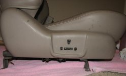
I had bought a 2001 4Runner Limited passenger seat and wanted to mix and match parts to have a driver’s seat with the best covers, cushions, heating elements, and also keep the lumbar support. With all this in mind, I needed to 1) remove the seat bottom from the 1999 and replace it with the 2001, 2) put the 2001 upper cushion, heating element, and cover on the 1999 upper frame so I could also keep the lumbar option.

Tools & Supplies - you may not need all of these, but this is what I used:
- Factory Service Manual - Components picture - Disassembly instructions
- Ratchet
- 3” ratchet extension
- 12, 14mm sockets
- Phillips screwdriver #2
- Flathead screwdrivers
- Sharpie
- 2 needle-nose pliers (I got by with one and a flat-nosed pliers)


Seat Removal

1) Pull off by hand or use a flathead screwdriver to pry up the 4 mounting bolt covers
2) Use a ratchet and 14mm socket to remove the 4 mounting bolts. Slide the seat all the way forward/backward to get easier access to the front/rear bolts.
3) Slide the seat so that it is close to the middle of the track.
4) Remove the headrest, put the upper part of the seat all the way in the upright position (not reclined).
5) Tilt the seat backwards and disconnect the electrical connection underneath (if you have power seats)
6) Remove seat


Seat Disassembly – separating the seat back from the seat bottom

7) Remove the power seat control knobs prying them with a flathead screwdriver.

07-powerknobsremoved.jpg~original


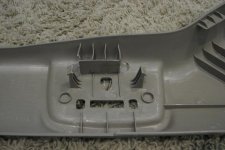
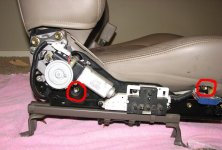
8) Remove the phillips screws (3 total) holding the side plastic seat covers. Two screws on the inside cover, one on the back of the outer cover. Now remove both covers. The outside one can be difficult so see the picture below to understand how it is clipped in. Using a longer flathead screwdriver can help release the built-in plastic clips from the seat track. The clip on the left side can be a pain.

09-insideofcover.jpg~original


9) Pull the bottom backside of the seat back downward to release it. Now lift that piece up and disconnect the electrical connection.

11-flapreleased.jpg~original


10) Remove two 14mm bolts on both sides of the seat at the base of the seat back. You can now separate the seat back from the seat bottom.

12-boltremoval.jpg~original


Separating the seat bottom from the seat track

11) Disconnect every electrical connection you can find – you may want to take pictures first so you have a reference for how everything goes back together. You will also need to pop some of the plastic mounting clips from the frame. This picture does not show all the connections.

13-seatbottomwiring.jpg~original


12) Remove 4 12mm bolts – 2 on each side of the seat. Separate the seat bottom from the seat track.

14-seatbottomremoval.jpg~original


Seat back disassembly

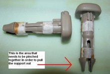
13) Remove the headrest supports. This step can be a real pain and the following text may be hard to follow. With one hand keep the leather on the backside pulled away from the frame. In your dominant hand have your flathead screwdriver ready. Use the screwdriver hand and reach down to one of the supports. Use your index finger to feel where the one side of the clip is pushed up against some metal. Slip your screwdriver between the metal and the clip. Take your other hand and reach around the outside of the seat to grab and pull on the headrest support. Now pinch half the clip with your finger, pry the screwdriver against the metal to push the other half of the clip in (now both sides of the clip should be squeezed together). Pull the headrest support out once you are able to pinch the clip.

13-headrestsupport.jpg~original


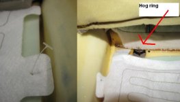
14) Now you can start pulling the leather cover off. It will help to push the padding around as you remove the cover. The heating pad has those plastic deals that you see holding tags to clothing. First I marked with a sharpie where they went through the fabric then pushed them through rather than cut them so they could be re-used. Another option would be to cut them and then use some small zip ties. You can pull about half of the leather up but then you will get to a point where it is held in by two hog rings. I used a flat-nosed and a needle-nose pliers to bend them open and remove the rings. Two needle-nose pliers would be best. Now you can pull the whole cover off.

14-plasticandhogring.jpg~original


Inside of leather cover with heating pad attached.

14-insideofleathercover.jpg~original


Backside of seat pad.

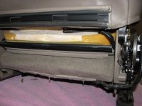
14-seatpad.jpg~original


Lumbar Motor disassembly

My lumbar motor was not working and I disassembled this a year ago so I am just providing pictures for taking it apart to help you put it back together. I have no idea what I did to get it working again…messing with the motor, disconnecting wiring, whatever…all I know is that it works again. So here are the pictures I took.

15-lumbarmotor-black.jpg~original


Seat bottom disassembly
I did not need to do this so you are on your own for this part. Hog rings hold the leather cover to the frame.

Seat Heater Wiring

So following this part of the write-up is super shady for you to do. My educational background in electrical wiring = NOTHING. I just look at the pretty pictures in the wiring diagram and try to understand them. I put my on/off switch in the factory location so the following is based off that.

The first thing I did was remove the electrical tape and plastic tubing from the 2001 seat track wire set so I could easily follow the individual wires. Next you want to cut the white-black wire coming from the seat back heater (if I remember correctly) and the blue wire coming from the seat cushion heater. Leave yourself enough wire to easily splice new wiring to those wires. You should now be able to remove a chunk of the factory seat track wiring with a total of 4 connectors...2 for the seat heaters, one each for the occupant sensor and seatbelt. Plug the connectors into the seat heaters. The other two connectors will remain unused.

Ground wire
Now you will need to add a length of wire to the white-black wire and you want to ground this somewhere.

Power wire

Disconnect your battery

The power wire needs to start after the ignition switch so that you can't accidentally leave the heater on after you turn the car off. That could be very bad. So....
With a ratchet, 3" ratchet extension and 10mm socket remove these 4 bolts. You can now pull the cover off (but not completely). Behind the ignition switch you will need to find this connector.

Find the black-yellow wire and splice a new wire into that. Then feed the new wire past the steering column (you can just have the new wire follow the clump of wires coming from this connector) and out through the hole for the on/off switch.

Add a in-line fuse holder to the end of the wire. I put in a 10amp fuse since normally it would have a 20 amp but I only have one seat heater....I just make this stuff up as I go so again, do this mod at your own risk. You could burn you car down, house, whatever. Messing with electrical stuff can be very dangerous.

Now send another wire from the on/off switch opening back to the seat and connect it to the blue wire.

You also need one more wire going from the switch to be a ground wire.

Power lumbar switch relocation
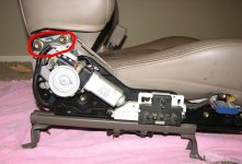
15-lumbarswitchrelocation.jpg~original
 

Attachments

  • 07-powerknobsremoved.jpg
    07-powerknobsremoved.jpg
    29.2 KB · Views: 306
  • 09-insideofcover.jpg
    09-insideofcover.jpg
    37.3 KB · Views: 308
  • 11-flapreleased.jpg
    11-flapreleased.jpg
    46.7 KB · Views: 318
  • 12-boltremoval.jpg
    12-boltremoval.jpg
    54.1 KB · Views: 305
  • 13-headrestsupport.jpg
    13-headrestsupport.jpg
    41.1 KB · Views: 291
  • 14-plasticandhogring.jpg
    14-plasticandhogring.jpg
    27.6 KB · Views: 304
  • 14-seatbottomremoval.jpg
    14-seatbottomremoval.jpg
    54.3 KB · Views: 308
  • 15-lumbarmotor-black.jpg
    15-lumbarmotor-black.jpg
    72.7 KB · Views: 302
Last edited:
Antenna Mast Replacement & Antenna Motor Cleaning

Problem – Your antenna mast will not move or will not extend/retract fully

Tools & Supplies
Antenna wrench or hammer and flathead screwdriver
10mm socket
Ratchet
Maybe ratchet extension & joint
More if you need to remove the fender

Parts
86337-35111 - Antenna Mast
90189-06028 - Fender Liner Clips


Remove Antenna Mast
1) Remove antenna nut. If you don’t have an antenna wrench use a hammer and flathead screwdriver.
IMG_39112_25.jpg~original


2) Remove mast.
Factory stereo – The motor runs longer using this method. While holding down the AM and FM buttons, turn the ignition key from “Lock” to “ACC.” The antenna mast will now pop out.
Aftermarket stereo – Turn on the radio and the mast will pop out.

Remove Antenna Motor
There are two ways to remove the antenna motor: the easy way and the long way. If you have a SR5 or live in a rust-free state you will probably get to do this the easy way. If you have a live in road salt hell you may have to go the long route.

Easy Way
Remove the fender liner clips. Some of them you can access from inside the engine bay and use a pliers or flathead screwdriver to push the clips out from the backside. I just broke off the one or two closer to the antenna motor that were not accessible through the engine bay. Here is what they look like:
IMG_3919_25.jpg~original


Pull the fender liner back and disconnect the electrical connector. This picture is with the fender completely removed but shows where the connector is.
IMG_3928_25.jpg~original


Remove the single 10mm antenna motor mounting bolt and slide the slide the motor out
IMG_3925_33.jpg~original


Long Way
My antenna motor mounting bolt was rusted on pretty decent and the mounting bracket was bending a lot trying to loosen the bolt. So I went the long route: remove grille, bumper, corner light, filler, running board, and fender.
Remove Grille
Remove Front Bumper
Remove Running Board
Remove Fender

Take a wire wheel to the exposed threads of the mounting bolt and clean them up. Now that you have the fender off, you can easily hold the mounting bracket in place and remove the mounting bolt.

Clean Out Antenna Motor
Disposable gloves recommended.
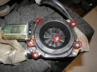
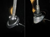
Remove the screws circled below and pull the cap off.
IMG_3934_25.jpg~original


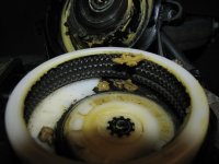
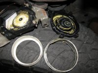
As you can see I had a good chunk of plastic teeth still in there.
IMG_3935_25.jpg~original

IMG_3936_25.jpg~original


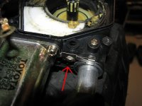
Put the cap back on. I had one screw that wouldn’t go back in and then noticed the nut for it came loose. Line that back up with the hole.
IMG_3937_25.jpg~original


Replace the antenna motor. I put some anti-sieze on the mounting bracket bolt threads so that I hopefully won’t have to take the pita route when the next mast breaks. Put everything back together.

Install New Antenna Mast

If you turned the key to off after pulling the old antenna out and have a factory stereo installed you want to hold down the AM and FM buttons, turn the ignition key from “Lock” to “ACC.” Let the motor finish running. Leave the key in the "ACC" position. The motor will now retract longer than it normally would. If you have an aftermarket stereo just turn it on.

Take the new antenna and insert the plastic teeth about 11 ¾” into the hole with the teeth facing the front of the vehicle (the FSM says to have the teeth facing the rear of the vehicle).
While applying some downward force to the mast teeth, turn the key back to “Lock.” The new mast should fully retract.
Screw the antenna nut back on.
 

Attachments

  • IMG_3919_25.jpg
    IMG_3919_25.jpg
    35 KB · Views: 221
  • IMG_3925_33.jpg
    IMG_3925_33.jpg
    49.8 KB · Views: 216
  • IMG_3928_25.jpg
    IMG_3928_25.jpg
    41 KB · Views: 213
  • IMG_3934_25.jpg
    IMG_3934_25.jpg
    62.3 KB · Views: 211
  • IMG_3935_25.jpg
    IMG_3935_25.jpg
    43.8 KB · Views: 221
  • IMG_3936_25.jpg
    IMG_3936_25.jpg
    65.8 KB · Views: 210
  • IMG_3937_25.jpg
    IMG_3937_25.jpg
    50.3 KB · Views: 216
  • IMG_39112_25.jpg
    IMG_39112_25.jpg
    30.2 KB · Views: 217
Last edited:
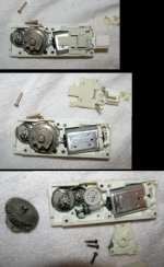
Transfer Indicator Switch Replacement

Problem – 4WD lights continuously blinking/flashing


A huge thanks goes out to 99SC4Runner over at yotatech. You will definitely want to read this thread:
4WD won't disengage on 99 4Runner LTD - YotaTech Forums


Tools
Ratchet
12mm socket
27mm combination wrench

Parts
84222-35070 - Transfer Indicator Switch (comes with the washer)


1) Remove the four 12mm bolts on the rear skid plate and remove the plate
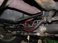
2) Disconnect the electrical connector and remove the switch - 27mm combination wrench

IMG_4992_25.jpg~original


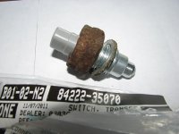
This is the old switch
IMG_4020_25.jpg~original
 

Attachments

  • IMG_4020_25.jpg
    IMG_4020_25.jpg
    36.7 KB · Views: 211
  • IMG_4992_25.jpg
    IMG_4992_25.jpg
    53.3 KB · Views: 210
Last edited:
Rear shock replacement


Use this guide at your own risk and double-check everything - procedure and specifications. The factory service manual can be a great help.


Tools & Supplies – you may not need everything listed:
- Factory Service Manual - Components diagram - Removal instructions
- Wheel chocks
- Jack & stands
- Breaker bar
- Impact driver
- Torque wrench
- Ratchet
- 14 deep, 17, 21mm sockets

Parts – Not all parts are necessary depending on what you want to reuse.

48531-80693 - 1999 tall shocks; 48531-80692 - 2002 shocks (2) (shocks come with the top bushings and top nut)
90948-A2004 - upper shock, top and bottom washers (4)
90948-02119 - upper shock, middle washer (2)
90948-03011 - lower shock, inner washer (2)
90948-03020 - lower shock, outer washer (2)
90385-19007 - lower shock, bushings (4)
91619-G1222 - lower shock, bolt (2)


1) Chock the front wheels
2) Loosen the lug nuts - breaker bare and 21mm socket
3) Raise vehicle and place jack stands
4) Remove lug nuts and wheel
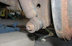
5) Remove lower shock bolt - impact driver and 17mm socket

06-lowershock.jpg~original


6) Remove top shock nut. Choices: ratcheting - put ratchet on the nut and twist the shock with wrench or by hand, cut just below the upper shock mount with a reciprocating saw, bend the shock back and forth until it snaps (this was easiest for me). Clean out the topside of the upper mount. Ratchet and 14mm deep socket

7) Replace the inner washer and bushing on the lower mount now if you want.

8) Put lower washers and bushing on top of shock, insert shock into upper mount, add bushing, washer, nut above the upper mount. Tighten down to 14 ft/lb.

10-rearshockassemblya.jpg~original


9) Add bushing, washer, and bolt to the lower mount. Tighten down to 47 ft/lb

12-lowermountbolt.jpg~original


10) Wire wheel lug nut studs if they are rusty. Put wheel back on. Hand-tighten lugs. Remove jack stand. Lower vehicle. Tighten lug nuts to 83 ft/lbs.
 

Attachments

  • 06-lowershock.jpg
    06-lowershock.jpg
    45.5 KB · Views: 219
  • 10-rearshockassemblya.jpg
    10-rearshockassemblya.jpg
    36 KB · Views: 243
  • 12-lowermountbolt.jpg
    12-lowermountbolt.jpg
    40.9 KB · Views: 228
Last edited:
Lower Ball Joint Replacement


Use this guide at your own risk and double-check everything yourself - procedure and specifications. The factory service manual can be a great help.


Tools & Supplies – you may not need everything listed:
- Factory Service Manual - Components diagram - Removal instructions
- Safety glasses
- Jack, jack stands, wheel chocks
- Wire wheel brush / wire brush
- Torque wrench (Range: 37ft/lb – 105ft/lb)
- Ratchet
- Breaker bare
- 14, 19, 21, 24mm sockets
- Vice Grips
- 19mm open-ended wrench
- Needle nose pliers
- Blue threadlocker
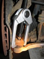
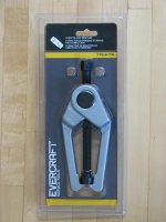
- Outer tie rod puller. I would recommend buying this on at Napa ($45) rather than getting one like Oreilly's rents. This puller can be used to separate both the tie rod and lower control arm.

10-outertierodpuller.jpg~original


Parts – part numbers are for my 4Runner and yours may be different. Not all parts are necessary depending on what you want to reuse.

43340-39465 - Lower Ball Joint - Left
43330-39585 - Lower Ball Joint - Right
00000-00000 - Lower Ball Joint Bolts - contact your dealer for your particular part number (8)
90171-16050 - Castle Nut to LCA (2)
90252-03015 - Cotter Pin to LCA (2)
90171-14042 - Castle Nut to Tie Rod (2)
95381-03225 - Cotter Pin to Tie Rod (2)


Removal
1) Chock the rear wheels
2) Loosen the lug nuts on the front wheels – 21mm socket
3) Jack up the front end, place your jack stands, lower the jack only enough so the frame is resting on the stands
4) Remove lug nuts and wheels – 21mm socket
5) Loosen, but don’t remove, the four ball joint bolts – 14mm socket
01-balljointbolts.jpg~original


6) Remove cotter pin and castle nut from tie rod end – needle nose pliers and 19mm socket
02-tierodcastlenut.jpg~original


7) Separate the ball joint from the tie rod
09-separatingtierod.jpg~original

03-tierodremoved.jpg~original


8) Remove cotter pin and castle nut from lower suspension arm – needle nose pliers and 24mm socket
04-lowersuspensionarmcastlenut.jpg~original


9) Separate the ball joint from the lower control arm
08-separatingLCA.jpg~original


10) Remove the four ball joint bolts and ball joint


Installation
11) Put the ball joint dust cover on the new ball joint. This is a picture of the old passenger side ball joint with the dust cover.
05-dustcover.jpg~original


12) Install lower suspension arm castle nut – torque to 105 ft/lb
13) Install a new cotter pin
14) Install tie rod castle nut - torque to 67 ft/lb. One time I had to use a vice grip on the very top non-threaded portion of the tie rod end to keep it from spinning while using a open-ended 19mm wrench to tighten down the castle nut. Once it is pretty tight you can use a 19mm socket and torque wrench.
07-installtierodcastlenut.jpg~original


15) Install a new cotter pin and bend like it was before
16) Install the four ball joint bolts with blue threadlocker – the FSM says 37 ft/lb for 2002 and 59 ft/lb for 1999
17) Put the wheel back on and get the lug nuts snug
18) Remove jack stands, lower the vehicle, remove wheel chocks
19) Torque the lug nuts to 83 ft/lb
 

Attachments

  • 01-balljointbolts.jpg
    01-balljointbolts.jpg
    52.9 KB · Views: 219
  • 02-tierodcastlenut.jpg
    02-tierodcastlenut.jpg
    47.5 KB · Views: 204
  • 04-lowersuspensionarmcastlenut.jpg
    04-lowersuspensionarmcastlenut.jpg
    75.2 KB · Views: 219
  • 06-bottlejacktrick.jpg
    06-bottlejacktrick.jpg
    72.2 KB · Views: 218
  • 07-installtierodcastlenut.jpg
    07-installtierodcastlenut.jpg
    59.4 KB · Views: 206
  • 08-separatingLCA.jpg
    08-separatingLCA.jpg
    32.8 KB · Views: 223
  • 09-separatingtierod.jpg
    09-separatingtierod.jpg
    42.6 KB · Views: 210
  • 10-outertierodpuller.jpg
    10-outertierodpuller.jpg
    28.1 KB · Views: 216
Last edited:
Transponder Key and Wireless Transmitter Programming - 1999-2002

I only state 1999-2002 because those are the only vehicles I have programmed personally.

You can get new transponder keys and used remotes on eBay. For the transponder key you will need to go to a hardware store and get it cut. Ace Hardware cut mine for free. For the remote transmitter you will very likely need to get one with the FCC ID #HYQ1512Y on the back.

I went through the motions a couple of times before doing the real thing to make sure I had the process down first. You need to do this fairly fast so it may help to practice once or twice first. Make sure when you depress and release the pedals that you push them all the way to the ground and release them completely.


Transponder Key Programming


1) Have your working key and new, cut transponder key with you and get into the 4Runner.
2) Close all the doors (not really sure if this is necessary).
3) Depress the brake and accelerator pedals down at the same time and release.
4) Within 5 seconds insert the programmed key into the ignition an turn it to “On.”
5) Within 15 seconds depress & release the accelerator pedal 5 times.
6) Within 20 seconds depress & release the brake pedal 6 times.
7) Remove the key from the ignition
8) Within 10 seconds insert the unprogrammed key into the ignition and turn it to “On.”
9) Within 10 seconds depress & release the brake and accelerator pedals 1 time.
10) Your security light will start flashing for 30-120 seconds. Once the security light stops flashing you are all set.
11) Try to start your car with the newly programmed key.


Wireless Remote Programming - Add Mode

The following steps will program a new remote but if there are already 4 remotes programmed to the vehicle, the first remote that was programmed will be erased.


1) Start with the driver’s door unlocked and open.
2) Insert the key into the ignition cylinder and then remove it
---(Complete steps 3 & 4 within 40 seconds)---
3) In one second intervals, press the door unlock then lock buttons five times. Unlock > Lock > Unlock > Lock > Unlock > Lock > Unlock > Lock > Unlock > Lock
4) Close the driver’s door then open it
---(Complete steps 5-8 within 40 seconds)---
5) Repeat step 3 sequence of unlocking and locking the doors
6) Insert the key into the ignition cylinder
7) Turn the key to “ON” and back to “LOCK” (one second interval between key turns)
8) Remove the key from the ignition cylinder
9) The doors should lock and unlock automatically one time. If they don’t, start over.
10) Within 1.5 seconds of the doors automatically unlocking and locking, press both the lock and unlock buttons at the same time on the remote transmitter.
11) Within 3 seconds of step 10, press either the unlock or lock button and hold for more than one second.
12) The doors should lock and unlock automatically one time.
13) Close the driver’s door to finish programming
14) Test the newly programmed remote.
 
Last edited:
Front Oxygen Sensor Replacement

Problem - CEL P0133

Parts - I found my sensor on amazon for about $50. Denso

2001 & 2002 4WD & 2WD V6; Front: 234-9002, Rear: 234-4261

2000 Cali 4WD manual V6; Front: 234-9001, Rear: 234-4153 2000
Cali 2WD manual V6; Front: 234-9001, Rear: 234-4155

1999 & 2000 Cali auto, 2WD/4WD V6; Front: 234-9002
1999 & 2000 Cali auto, 2WD V6; Rear: 234-4155
1999 & 2000 Cali auto, 4WD V6; Rear: 234-4153

1999 California manual V6 2WD/4WD 4Runner; Front = 234-9003
1999 California manual V6 4Runner; 2WD Rear = 234-4155
1999 California manual V6 4Runner; 4WD Rear = 234-4153

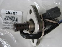
1999 & 2000 49 State 2WD & 4WD auto V6; Front = 234-4162
1999 & 2000 49 State 2WD & 4WD auto V6; Rear = 234-4162

1999 & 2000 49 State manual V6 2WD; Front: 234-4162
1999 & 2000 49 State manual V6 4WD; Front: 234-4161
1999 & 2000 49 State manual V6 2WD & 4WD; Rear: 234-4154


1996-1998 4WD manual V6-3.4; Front = 234-4161
1996-1998 4WD manual; Rear = 234-4154

1998 2WD ALL Front = 234-4162; Rear 234-4154

1996-1998 Auto 4WD V6 3.4; Front = 234-4162
1996-1998 Auto 4WD V6 3.4; Rear = 234-4154

1997 Auto 2WD; V6 3.4 Front = 234-4162, Rear = 234-4153
1997 Manual 2WD; V6 3.4 Front = 234-4161, Rear = 234-4153

1996 All 2WD; V6 3.4 Front = 234-4162
1996 All 2WD; V6-3.4 Rear = 234-4153


New sensor
IMG_3721_25.jpg~original


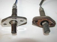
New and old sensors
IMG_3732_25.jpg~original


Of course my bolt for the electrical connector mount snapped off
IMG_3738_25.jpg~original


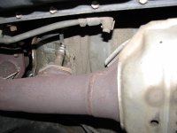
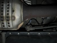
Oxygen Sensor - 10mm deep socket or combination wrench
IMG_3725_25.jpg~original
 

Attachments

  • IMG_3721_25.jpg
    IMG_3721_25.jpg
    41.4 KB · Views: 203
  • IMG_3725_25.jpg
    IMG_3725_25.jpg
    40.2 KB · Views: 197
  • IMG_3732_25.jpg
    IMG_3732_25.jpg
    33.7 KB · Views: 209
  • IMG_3738_25.jpg
    IMG_3738_25.jpg
    31.6 KB · Views: 201
Last edited:
Some really detailed write ups there. Will definitely come in handy for some folks. You really dig the sport hoods!
 
I saw this thread the other day when you first posted it. I saw you were tirying to tie up some post so I didn't want to interrupt what you had going on. Looks good thou. I like it.
 
I will be selling my Toytec Ultimate Lift sometime soon...preferably once it warms up a little. 600# coils/OME 906/OME 60028/brand new diff drop kit...150-300 miles on the lift. I just need to hook a battery up to the 4Runner to see the odometer and then I can get an exact mileage. If you are interested pm me an offer including shipping. I may be willing to sell only the rear coils and shocks.

Interested in the 906 coil setup...PM sent
 
Rear coil replacement


Use this guide at your own risk and double-check everything - procedure and specifications. The factory service manual can be a great help.


Tools & Supplies – you may not need everything listed:
- Factory Service Manual - Components diagram - Removal instructions
- Safety glasses
- Wheel chocks
- Jack
- Jack stand
- Wire wheel brush / Wire brush
- Torque wrench
- Impact gun - strongly suggested that you have one
- Ratchet
- 12, 17, 21mm sockets
- 14, 17mm open ended wrenches
- Extension joint

Parts – part numbers are for my 4Runner and yours may be different. Not all parts are necessary depending on what you want to reuse.

48231-35210 - 1999 Rear tall coils (2)
94183-00831 - Rear endlink top nut (2) - FSM says non-reusable part
90105-12288 - Lateral control arm bolt (2)
94622-31200 - Lateral control arm washer (2)
90170-12039 - Lateral control arm nut (2)


1) Chock the front wheels.
2) Loosen the lug nuts - 21mm socket.
3) Raise vehicle and place jack stands under the frame.
4) Remove wheels.
5) Remove lower shock bolt - 17mm socket. Pull the lower end of the shock off the mount.

06-lowershock.jpg~original


6) Disconnect the stabilizer bar. Two options here: a) Remove rear endlink top nut, retainer, bushing. 12mm deep socket on the top nut with possibly a extension joint and a 14mm open ended wrench for below all the bushings and washers. After disconnecting and later lowering the axle, you can spin the endlink upside down and take a wire wheel to the threads if they need cleaning. b) Remove the two brackets holding the stabilizer bar in place. I went with option a.

IMG_4685_30.jpg~original


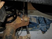
7) Remove lateral control arm bolt, washer, nut. You only need to disconnect one end. 17mm open ended wrench and 17mm socket. I removed the one in the first picture (driver’s side), but the one in the second picture is probably easier to access.

IMG_4674_25.jpg~original

IMG_4675_25.jpg~original


8) With the frame resting on the jack stands you can now start to lower your jack holding up the axle.

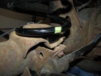
9) Now you can push down on the axle and pull the old coil out with the inner bump stop. Install the new coil and bump stop. Make sure that the coil is seated correctly in the lower mount.

IMG_4670_25.jpg~original


10) Once you have both coils replaced and seated correctly raise the axle back up until the lateral control arm is lined up to insert the bolt, washer, nut. Torque down to 64 ft/lb.
11) Reinstall the endlinks. Should go bottom to top….retainer, bushing, retainer - mounting plate - bushing, retainer, nut. Torque down to 14 ft/lb.
12) Reinstall the rear shocks. Torque down 47 ft/lb.
13) Wire wheel lug studs if they are rusty. Put wheel back on. Hand-tighten lugs. Remove jack stand. Lower vehicle. Tighten lug nuts to 83 ft/lb.
 

Attachments

  • IMG_4670_25.jpg
    IMG_4670_25.jpg
    45.2 KB · Views: 130
  • IMG_4674_25.jpg
    IMG_4674_25.jpg
    45.3 KB · Views: 115
  • IMG_4675_25.jpg
    IMG_4675_25.jpg
    44.9 KB · Views: 130
  • IMG_4685_30.jpg
    IMG_4685_30.jpg
    57.1 KB · Views: 130
Last edited:
Just stumbled across this thread, some GREAT DIY's in here, thanks for the effort! I'll be using the seat bottom swap one shortly!
 

Members online

Forum statistics

Threads
278,305
Messages
3,554,042
Members
248,016
Latest member
Advally Service

Trending content

Back
Top