Steering Knuckle Removal
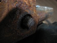
I found out after driving my 4Runner for 30k that some mechanic at a Toyota dealership snapped one of my lower ball joint bolts and “fixed” it while doing the ball joint recall. His fix was to leave the broken bolt in the steering knuckle then take the snapped off portion of the bolt and shove it into place with black silicone. I decided to take the knuckle into a shop and have them remove remaining bolt and replace the upper ball joint while the knuckle was out.
I was working on the driver’s side but some pictures are of the passenger side since some pictures didn’t come out very clear.
Use this guide at your own risk and double-check everything - procedure and specifications. The factory service manual can be a great help.
Tools & Supplies – you may not need everything listed:
-
Factory Service Manual
- Safety glasses
- Wheel chocks
- Jack
- Jack stands
- Torque wrenches (21
in/lbf – 174
ft/lbf)
- 10, 12, 14, 17, 19, 21mm sockets
- 19mm open ended wrench
- Breaker Bar
- Chisel or screwdriver
- Rubber or plastic mallet
- 1 3/8” socket (3/4”)
- 1/2” female to 3/4” male socket adapter (for my 1/2” breaker bar and 1 3/8” socket)
- Needle nose pliers
- Metal hanger or a box to set the caliper on
- Ball joint puller (mine is from Napa - $45)
- Blue threadlocker
Parts – part numbers are for my 4Runner and yours may be different. Not all parts are necessary depending on what you want to reuse.
95381-04045 – Axle Hub Cotter Pin
43525-35010 – Axle Hub Lock Cap (reused)
90179-28007 – Axle Hub Lock Nut (reused)
xxxxx-xxxxx – Upper Ball Joint Cotter Pin
1) Chock the rear wheels
2) Loosen the lug nuts - 21mm socket
3) Raise vehicle and place jack stands under the frame
4) Remove wheel
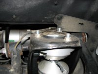
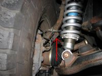
5) Remove lower shock bolt - 19mm socket and 19mm open ended wrench. Remove the three 14mm nuts at the top of the shock but do NOT remove the center nut (if you have a stock setup).
(Picture of lower bolt coming soon)
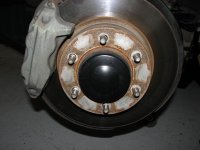
6) Remove the grease cap. I used a sharp, 1” wide chisel. Work your way around the grease cap and eventually it will pop off.
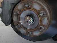
7) Remove cotter pin (needle nose pliers). Remove the lock cap (by hand). Loosen the lock nut. To loosen the lock nut, you need someone to press the brake pedal down while you loosen the nut (breaker bar, 1/2” to 3/4” adapter, 1 3/8” socket)
8) Remove the ABS speed sensor bracket from the knuckle (10mm socket)
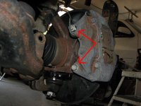
9) Remove the brake/ABS bracket from the knuckle (12mm socket). Picture is of the passenger side.
10) Remove the ABS speed sensor from the knuckle (10mm socket). Once the bolt was removed I used a chisel to carefully pry the sensor out.
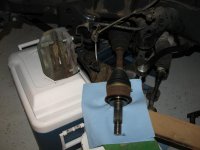
11) Remove the two caliper bolts (17mm socket). Be careful when pulling out the second bolt as the caliper is heavy and may fall on you. Mine was stuck in place pretty good so I didn’t have to worry about that. Use a metal hanger to hang the caliper (so you can avoid disconnecting the brake line) or have a box tall enough to rest the caliper on. I found my cooler did the job.
Cooler in action (picture taken after everything was removed)
12) Try to remove the rotor. I left the rotor on until the knuckle was completely removed. If you want to try to remove it now, put three lug nuts back on every other stud. The point of the lug nuts is to keep the rotor from completely falling off the lug studs and to the ground when you are hitting the backside of it. Now hit the backside of rotor with a rubber mallet. If the rotor pops free, remove the lug nuts and rotor. If you live in a rust free state you should have no problems removing the rotor now.
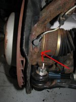
12) Remove the 4 lower ball joint bolts. Two of bolts are pictured here (leave the cotter pin and castle nut alone)
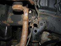
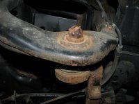
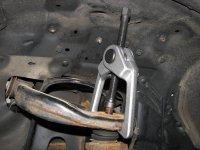
13) Separate the upper ball joint from the upper control arm. Remove the cotter pin and castle nut. Pop the upper ball joint free with a puller. I tightened the puller down some then hit the upper control arm lightly with a hammer. Get ready for a loud bang. Now the upper ball joint is separated from the upper control arm.
14) While pulling the steering knuckle out towards you, hit the drive shaft stud (the end where you removed the lock cap and lock nut from) in with a rubber mallet. A few whacks should be enough.
15) Finally, access to the broken ball joint bolt. Need anymore proof Toyota dealerships are no better than any other shop? I certainly don’t.
Reassembly - at this moment in time everything is still apart so I am just going to provide the torque specs for my 4Runner.
Upper Ball Joint Castle Nut – 80 ft/lbf - Don’t forget to put in a new cotter pin and bend it like the old one. The cotter pin may not line up with hole in the upper ball joint and castle nut. I have seen a Toyota FSM (Sequoia maybe) where it says to continue tightening up (to some certain extent) until everything does line up.
Lower Ball Joint Bolts - torque specs are tricky. 1999 FSM says 59 ft/lbf, 2002 FSM says 37 ft/lbs. I have no idea why they are different. The Sequoia FSM (for what it's worth) says 37 on the two bolts going through the dust cover, 59 on the other two not going through the dust cover. General consensus around this forum is to at least use blue threadlocker on all the bolts. You should probably wait to fully tighten these down until after you have the coilover top nuts and lower bolt in place.
Brake Caliper Bolts - 90 ft/lbf
ABS Speed Sensor - 71
in/lbf
Brake Line Bracket - 21
in/lbf
ABS Speed Sensor Bracket - 71
in/lbf
Drive Shaft Lock Nut - 174 ft/lbf - Don't forget the lock cap and cotter pin
Coilover Top Nuts - 47 ft/lbf
Coilover Lower Bolt - 101 ft/lbf
Lug Nuts - 83 ft/lbf - don't torque down until the wheels are back on the ground.
Please let me know if you find in omissions, errors, have a better method, I did something stupid/dangerous, whatever... I will be going over this post when I put everything back together to double-check the accuracy of this write-up.