Bussmann Relay Box. Could some check my thought process?

Krayziekid

New member
So I am slowly beginning to add some electrical mods to my 4Runner, and now that seem to have stumbled in to some free time, I am thinking about making on of those Bussmann Relay boxes. Currently I only have one accessory that requires a relay, with another one on the way. I also have two other non-relay accessories. It would be nice to have this all run to one spot instead of the spaghetti of wires currently found in my engine bay. I am not super great when it comes to electrical/wiring, but I think with enough time I could figure this out.

So first and foremost, here is a parts list:

1x -Bussmann Panel: 5 Micro-Relays and 10 Fuses

5x -35A SPDT Relays

50x -18-16Ga Pin Terminals

50x -14-12Ga Pin Terminals

100x -Cable Plugs

100x -18-16Ga Cable plugs

100x -14-12Ga Cable plugs

100ft -1/4" Wire Loom

4x -Female 6pin connectors

4x -Male 6pin connectors

I think that should be everything I need besides the actual wire, a pair of crimpers, and some heatshrink, which I will pick up separately. Long story short, I ran into a build thread by [MENTION=46025]HokieRunner[/MENTION] and was a huge fan of the relay box he built. I really want to do something similar because it seems very easy to connect/disconnect and it seems very upgrade-able. I'd love to be able to make all of these quick disconnects/wiring harnesses and run them for future use.

I will admit, I'm not an expert when it comes to relay wiring, but I think it'll be a good learning experience. The only other questions I have are:

1. Do I just run two fatter (4Ga) wires from the relay box posts to the battery positive and negative?

2. Is there a major difference between a SPST and SPDT relay?

Any and all advice would be helpful, and if I can get this done, I would love to make a how-to guide for everyone.

Edit: Also, when it says minimum order quantity: 50, I'm assuming I have to order 50, despite the title already saying 50/bag?
 
Last edited:
Register to hide this ad
This would be a great learning experience if that's what you're looking for. The downside is you have to buy 100 of each little part when you need only a few. That being said, I went down this road as well and by the time I added up all the cost, it pretty much washed with buying a complete unit. I picked up two from this guy and they were excellent quality.

Universal Relay/ fuse auxiliary distribution box jeep, Cooper Bussmann Off Road

Also, make sure you get the properly bussed panel. #15303-5 is probably the one you want.
 
Last edited:
This would be a great learning experience if that's what you're looking for. The downside is you have to buy 100 of each little part when you need only a few. That being said, I went down this road as well and by the time I added up all the cost, it pretty much washed with buying a complete unit. I picked up two from this guy and they were excellent quality.

Universal Relay/ fuse auxiliary distribution box jeep, Cooper Bussmann Off Road

Also, make sure you get the properly bussed panel. #15303-5 is probably the one you want.

Wow, I didn't even realize that was a thing. Honestly, that might be the way to go, simply because you are right, I would be left over with hundreds of extra pieces that I wouldn't need unless I wanted to make multiple of them. And I don't really see myself needing to make two anytime in the near future. I might go this route.

Quick question about it though. I currently have a light bar with a pre-wired harness/relay. So would I just cut the pos/neg leads off the light bar and solder them to the new cables coming out of the relay box?

Also, would i just crimp, solder, etc to lengthen the cables, or do you think it would still be a good idea to get a quick disconnect plug and terminate all of the wires with terminals in order to make disconnecting easy? Thanks!
 
Quick question about it though. I currently have a light bar with a pre-wired harness/relay. So would I just cut the pos/neg leads off the light bar and solder them to the new cables coming out of the relay box?

Also, would i just crimp, solder, etc to lengthen the cables, or do you think it would still be a good idea to get a quick disconnect plug and terminate all of the wires with terminals in order to make disconnecting easy? Thanks!

For the light bar, you could snip out it's existing harness and solder it to a fused relay output from the relay box. You could bring the ground wire back there as well, but a chassis ground nearby on the car would work just as well (the negative wire on the relay box is for grounding the relay coils, not return for all the fused circuits). Just make sure the relay and fuse are rated for however many amps your light bar draws.

Crimp/solder is fine to lengthen the cables out of the relay box, but I always prefer to put a connector near whatever doodad I'm installing to make removal simpler. If you put all the connectors near the relay box instead, you'll make it easy to plug the wrong device into the wrong circuit.
 
Quick question about it though. I currently have a light bar with a pre-wired harness/relay. So would I just cut the pos/neg leads off the light bar and solder them to the new cables coming out of the relay box?

Also, would i just crimp, solder, etc to lengthen the cables, or do you think it would still be a good idea to get a quick disconnect plug and terminate all of the wires with terminals in order to make disconnecting easy? Thanks!

There's no reason you couldn't keep that one wired the way it is. But yes, you could just cut out that relay and splice the wires into the box.

There's a couple schools of thought when it comes to QD plugs and spade connectors. Yes you can easily disconnect and remove. The problem is it makes it that much easier for thieves. On the other hand, if someone wants to steal you light, they're going to rip and pull and f-up all your wiring. I'm putting spade connectors under a layer of shrink wrap so that i can slice open the shrink wrap and quickly disconnect but its not advertised as such.
 
There's no reason you couldn't keep that one wired the way it is. But yes, you could just cut out that relay and splice the wires into the box.

There's a couple schools of thought when it comes to QD plugs and spade connectors. Yes you can easily disconnect and remove. The problem is it makes it that much easier for thieves. On the other hand, if someone wants to steal you light, they're going to rip and pull and f-up all your wiring. I'm putting spade connectors under a layer of shrink wrap so that i can slice open the shrink wrap and quickly disconnect but its not advertised as such.

So you would just suggest lengthening the wires to where I need them to go (lets say switches for example) and just put spade connectors on there so I don't mix up a wire near the relay box?
 
So you would just suggest lengthening the wires to where I need them to go (lets say switches for example) and just put spade connectors on there so I don't mix up a wire near the relay box?

It's really not that complicated. Your switches probably accept spade connectors of some type or have a unique connector designed for them. Just hard wire everything together the whole way and use different colored wires for the different circuits or label them. Get some shrink wrap and techflex as well.
 
SPST is single pole, single throw SPDT is single pole, double throw.

Verbally, spst is a single feed that is connected/disconnected based on switch position. Spdt is a single feed that can be wired normally closed, NC, or normally open, NO. Another way to look at it is the single feed can connect to two loads, mutually exclusive, depending on switch position.

You can use any spdt switch in place of a spst, but not necessarily the other way around.

WRT relay wiring, the NO/NC becomes more important. Typically one uses a switch to close the loop on the coil, the coil throws the pole from the NC position to the NO position.

Lights, leds, horns, most applications get wired to the NO on a relay. This configuration applies voltage to the load when the coil is energized.

I'm having trouble right now thinking of common applications to use NC side of a relay. Typically for something you want to cut power to when something else comes on.

Hopefully this is clear. Schematics & diagrams should be your friend.
 
Ok so after weighing my options, I do think I'm gonna go ahead and try to build one. I think it'll be a nice learning experience and it will allow me to completely customize it the way I want it to be. I am not going to do the quick disconnects that I listed above, as it is simply another thing to go wrong. It should be easy enough to pull wires if I need to.

I have one last question though. For wiring on this, there are two bussed circuits with nuts for running a wire. I think wiring it so that one is power and one is ground would be easiest, but doesn't that mean the relay box will always powered? Could that cause auxiliary power drain? Don't really want to run my battery dry!
 
I have one last question though. For wiring on this, there are two bussed circuits with nuts for running a wire. I think wiring it so that one is power and one is ground would be easiest, but doesn't that mean the relay box will always powered? Could that cause auxiliary power drain? Don't really want to run my battery dry!

From the datasheet, that relay/fuse box has 2 busses: 1 for the fused outputs, and 1 for the relay outputs. Each bus can handle 80A, so size the supply wires (and supply fuses) appropriately. You need to supply +12V to each bus so that you can have +12V fused circuits on the fused side and switched +12V on the relay side. *Unless you want to go with a switched-ground wiring scheme for the relays, but I'm thinking you probably don't.

If you wire the busses to the battery +12V, yes the box will always be "powered" in the same sense that your existing fuse box is always powered: There's always voltage present at it, but none of the circuits are drawing current when the truck is off (well, there's a small draw for the clock and things but it's minimal) so the battery isn't being drained. Alternatively, you can wire a high current relay in the supply to the fuse bus such that the relay only closes when the truck is on; those subsequent circuits would then only be active when the truck is on.

You shouldn't need to bring a high current ground to the fuse box, just a smaller wire to serve as the return for the relay coils.
 
From the datasheet, that relay/fuse box has 2 busses: 1 for the fused outputs, and 1 for the relay outputs. Each bus can handle 80A, so size the supply wires (and supply fuses) appropriately. You need to supply +12V to each bus so that you can have +12V fused circuits on the fused side and switched +12V on the relay side. *Unless you want to go with a switched-ground wiring scheme for the relays, but I'm thinking you probably don't.

If you wire the busses to the battery +12V, yes the box will always be "powered" in the same sense that your existing fuse box is always powered: There's always voltage present at it, but none of the circuits are drawing current when the truck is off (well, there's a small draw for the clock and things but it's minimal) so the battery isn't being drained. Alternatively, you can wire a high current relay in the supply to the fuse bus such that the relay only closes when the truck is on; those subsequent circuits would then only be active when the truck is on.

You shouldn't need to bring a high current ground to the fuse box, just a smaller wire to serve as the return for the relay coils.

Lol ok I understood a few of those words. I am currently in the process of drawing a wiring diagram. I'll post it here when I am done. Would you mind taking a look when I post it?
 
No problem.

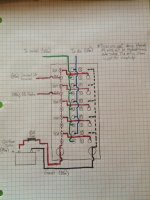
Ok so here is what I came up with. I think it should all work, but please let me know what you think. Edit: Sorry if this is too small. I could make it bigger if you need it.

Bussmann Relay Box.jpg

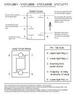
The only thing I am a little confused about is the switch wiring. This is a switch I currently have, and I cannot figure out how to get that damn lower LED to work. The wire coming out of the box labeled "To Switch" will go to pin 3 (daisychained to other switches). The constant 12V will go to pin 2 (daisychained to other switches). Pin 7 will be daisychained and grounded, as will Pin 8, although they will be separate. That is how I currently have it and the upper LED comes on. I tried tapping a fuse in my normal fuse box and connecting it to 6 for the lower LED, but that didn't work. I don't want to damage the factory wiring too much, so I might use a T-Tap on a wire in an unused switch that I know only comes on with the dash lights. Then I'll daisy chain that to the rest of the switches. Would that work? Here is the diagram for reference.

OTRATTW Switch Wiring.JPG
 

Attachments

  • Bussmann Relay Box.jpg
    Bussmann Relay Box.jpg
    67.1 KB · Views: 6,118
  • OTRATTW Switch Wiring.JPG
    OTRATTW Switch Wiring.JPG
    114.5 KB · Views: 2,514
Thanks for the diagram! Pictures make this much easier.

Pre-edit: <s>I think your diagram has the relays flipped around, as if they were installed 180* backwards. The fuse box shouldn't be supplying a common bus to the coil (pin 86 on the relay), but rather the switch pole (pin 30).</s> Now I think I was wrong and your diagram is correct. This changes a bit of what I was saying in previous posts as well, sorry!

Okay, so first: The dotted red supply bus from the battery to the fuses would terminate at the unseen terminals (like you did for the dotted black line to the relays). Your circles there are the fused outputs from that bus, half of which you've routed over to the relay circuits (pin 87). Not important, but you could route those wires to pin 30 instead to have a slightly shorter/cleaner run. Your blue wires would then move over to pin 87.

The outputs from the relays are your blue lines, I'm reading your note to say that you realize each circuit gets it's own blue wire (so 5 total leaving the box). Those will supply relay controlled fused high current power to your accessories.

To turn the relays on/off, you have your switches providing switched +12V on the green wires to the relay coils (pin 85), and the coils grounded via pin 86 and the common bus within the box. That'll work fine, <s>but if you reverse this control scheme your wiring will become slightly simpler...</s> *The benefits are negated since you're using lighted switches and will have +12V at the switch anyway.

You don't need #8 for the battery ground wire; it's only carrying the relay coil currents, which will be about half an amp for all 5 of them combined - even #18 is overkill! You also don't have to run it all the way back to the battery, any good chassis ground spot will do.

All told, your schematic should work fine! Sorry for trying to steer you wrong before - some of the diagrams are top down, others are bottom up, spacial manipulation can be tricky.

As for the switch wiring: You can't daisy chain pin 3 on the switch to other switches/relays, that's it's individual switched output and should go to a single relay's coil contact (pin 85). i.e. you should have a bundle of 5 green wires coming out of your relay box, just like the blue wires. You're fine with what you're thinking on pins 2, 7, and 8. For pin 6, I don't know why tapping a fuse didn't get it to illuminate; it should work fine if you supply it +12V as long as pin 7 is grounded. Maybe jumper pin 6 to pin 2 just for a quick test - if it lights up, all is good. After that, you'd be fine tapping into an existing illumination wire on some other switch (can't help you with which one though, sorry) and then daisy chaining that to the rest of your switches.

Hope that helps, and good luck!
 
Last edited:
Been there, struggled through it...

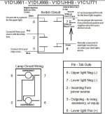
[MENTION=127401]Krayziekid[/MENTION] The front of my 2005 4Runner use to be lit up like a Christmas Tree (as someone once commented, haha) and having been there and struggled through the electrical connections to the OTTWATTW switches let me help you out. Attached is what will work.
I hope this helps you.
 

Attachments

  • otrattw.JPG
    otrattw.JPG
    59.3 KB · Views: 726
Thanks for the diagram! Pictures make this much easier.

Pre-edit: <s>I think your diagram has the relays flipped around, as if they were installed 180* backwards. The fuse box shouldn't be supplying a common bus to the coil (pin 86 on the relay), but rather the switch pole (pin 30).</s> Now I think I was wrong and your diagram is correct. This changes a bit of what I was saying in previous posts as well, sorry!

Okay, so first: The dotted red supply bus from the battery to the fuses would terminate at the unseen terminals (like you did for the dotted black line to the relays). Your circles there are the fused outputs from that bus, half of which you've routed over to the relay circuits (pin 87). Not important, but you could route those wires to pin 30 instead to have a slightly shorter/cleaner run. Your blue wires would then move over to pin 87.

The outputs from the relays are your blue lines, I'm reading your note to say that you realize each circuit gets it's own blue wire (so 5 total leaving the box). Those will supply relay controlled fused high current power to your accessories.

To turn the relays on/off, you have your switches providing switched +12V on the green wires to the relay coils (pin 85), and the coils grounded via pin 86 and the common bus within the box. That'll work fine, <s>but if you reverse this control scheme your wiring will become slightly simpler...</s> *The benefits are negated since you're using lighted switches and will have +12V at the switch anyway.

You don't need #8 for the battery ground wire; it's only carrying the relay coil currents, which will be about half an amp for all 5 of them combined - even #18 is overkill! You also don't have to run it all the way back to the battery, any good chassis ground spot will do.

All told, your schematic should work fine! Sorry for trying to steer you wrong before - some of the diagrams are top down, others are bottom up, spacial manipulation can be tricky.

As for the switch wiring: You can't daisy chain pin 3 on the switch to other switches/relays, that's it's individual switched output and should go to a single relay's coil contact (pin 85). i.e. you should have a bundle of 5 green wires coming out of your relay box, just like the blue wires. You're fine with what you're thinking on pins 2, 7, and 8. For pin 6, I don't know why tapping a fuse didn't get it to illuminate; it should work fine if you supply it +12V as long as pin 7 is grounded. Maybe jumper pin 6 to pin 2 just for a quick test - if it lights up, all is good. After that, you'd be fine tapping into an existing illumination wire on some other switch (can't help you with which one though, sorry) and then daisy chaining that to the rest of your switches.

Hope that helps, and good luck!

Thank you for all of your help! No worries about "trying to steer me wrong" lol. The reason I went with this layout was simply because if I switched the relays around (i.e. reversed them), then I would still get one bus for power but the other bus would be the pins for the switch activation. Not sure how I would bus that, as you mentioned I can't daisychain those. I know I can't daisychain them. I have no clue why I said I was going to lol.

I have seen other bussmann boxes like this with only one post for grouping connections (like I have with my Pos and Neg busses). These have more pin openings and probably offer more "customization" but I figured if I can make a common power and common ground simple, why wouldn't I? Also thanks for the heads up about the ground wire size.

Yea I am trying to use lighted switches. They are lit on the bottom when off, and then lit on the top and bottom when on. I still can't figure out the bottom light though. That one wire labeled constant 12V for switch is simply a fused connection from the box to the switches that will eventually get daisychained to other switches. That will allow the top light to turn on while activated. I am going to play around with other wires and fuses and stuff, but at this point I am thinking I may have gotten a bum switch. Might order another one simply to see if that is the case.

Thanks for all of your help!!! I am likely going to be attempting this over the next few weeks, so I'll probably be heading back your way if I have any questions. Probably gonna make a build thread too.
 
[MENTION=127401]Krayziekid[/MENTION] The front of my 2005 4Runner use to be lit up like a Christmas Tree (as someone once commented, haha) and having been there and struggled through the electrical connections to the OTTWATTW switches let me help you out. Attached is what will work.
I hope this helps you.

Question. Do those wire color labels on there correspond to the wires from the relay box I posted earlier? Or should I mainly just be looking at the two on the right (the top and bottom pins). If so, am I T-Tapping those two wires from an existing switch? Sorry about all the questions, but I really appreciate it!
 
Question. Do those wire color labels on there correspond to the wires from the relay box I posted earlier? Or should I mainly just be looking at the two on the right (the top and bottom pins). If so, am I T-Tapping those two wires from an existing switch? Sorry about all the questions, but I really appreciate it!

I don't know what lights/ accesories you are using or what the harness looks like so if you can correlate to the colors of the Rigid Industries Harness then the left side of the switch could be useful to you...
However, I posted mainly for the right side wire colors to try to help you out. Yes, I just t-tapped as you say, into those existing wire colors, which can be found on the back side of any dimmable switch on your dash or center console. Don't overcomplicate that part of the wiring. Find the closest switch that dims next to your install and tap there (then daisy chain for your other switch bottom lights on the right side of the OTTRATTW switches, done.)..
 
I don't know what lights/ accesories you are using or what the harness looks like so if you can correlate to the colors of the Rigid Industries Harness then the left side of the switch could be useful to you...
However, I posted mainly for the right side wire colors to try to help you out. Yes, I just t-tapped as you say, into those existing wire colors, which can be found on the back side of any dimmable switch on your dash or center console. Don't overcomplicate that part of the wiring. Find the closest switch that dims next to your install and tap there (then daisy chain for your other switch bottom lights on the right side of the OTTRATTW switches, done.)..

Ok, one final question. When you say dimmable, you mean these switches will only light up when the dash lights are on right? They will be off otherwise?

Thank you so much for all of your help!
 

Members online

Forum statistics

Threads
278,312
Messages
3,554,089
Members
248,016
Latest member
Advally Service

Trending content

Back
Top