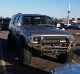
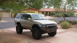
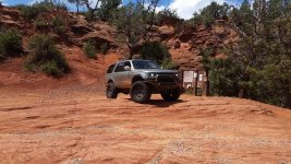
D Farms' Build thread: "Goldilocks"

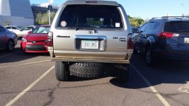
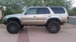
after a wheeling trip the other day the outer ply of one of my balding tires cracked open. I ended up having to put the spare on. so im finally getting new tires, specifically the bfg ko2 in 315/75r16. I ordered them from the local 4wheel parts, along with a warranty that actually covers going offroad, and i dont have lie about it. they had one in stock and had to order the other 3. with all 4 tires, mounting, balancing, the warranty, minus the rebate it came out to about $1100. not bad for 35s, and good ones at that. I had them mount the one they had on the wheel i had to take off, which is perfect since I needed to clearance my wheel wells anyways.

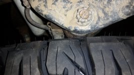
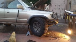
When i put in my poly bushing a few posts ago I cut and welded my ucas to clear bigger tires. so I went to put the 35" on and it cleared the uca, on a stock 16x7 wheel. unfortunately the tire was actually touching on the spindle... so I reluctantly ordered some wheel spacers.

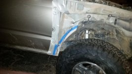
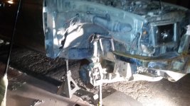
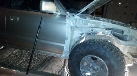
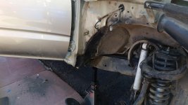
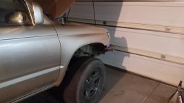
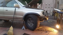
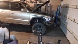
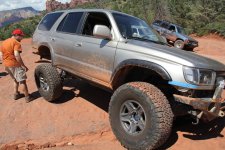
last night i stayed up cutting and welding up my passenger wheel well, and it easily clears a 35"or maybe even a 36". I will say a big hammer can do a lot of work, but there were certain parts that were reinforced and had to be cut. I also hammered after I cut and it was very effective.I put the truck on jack stands and took the coilover out. I then put the 35 on and jacked it all the way up and compressed the bumpstop as much as I could, and turned the wheel left and right. as predicted it rubbed the pinch weld and a lot of the inner fender wall.
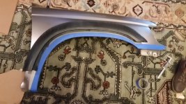
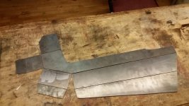
so I marked with blue tape and cut it out with the angle grinder. Its not nesessary to make the cut that wide, but it helps to go deep after a wheeling trip the other day the outer ply of one of my balding tires cracked open. I ended up having to put the spare on. on the bottom I cut all the way back to the first bolt hole and then curved the cut up and terminated the cut at a sharp angle in the sheet metal(hard to explain unless you are looking at it). then I cut along the inner fender wall to make a sort of triangle shape. once i had cut it, me and my bfh went to town and I was able to pound the entire fender well out where it might rub. after I was satisfied, I bolted the tire back on and jacked it back up and turned the wheel left and right. It cleared the back of the fender but the stupid windshield fluid resivoir was in the way. I removed the windshield fluid resevoir and relocated it into the engine bay, just had to move a fuse box over a bit and the fluid lines were right next it anyways. Once that was done I checked again and now it was rubbing the front still. this part was a double reinforced sheet and a lot more difficult to bend. out came the sledge. checked again and it was good, about 1.5"+ clearance all around, keep in mind i havent put the spacers on. after that I plasma cut some 16 gauge steel to cover what i had cut and welded it in, only starting one fire in my truck... ill need a new passenger door plug, shit got melted. it took about 3 hours to get to the point where I was welding, minus the windshield washer relocation. welding it took a lot longer, the sheet metal was really thin, and im used to the thick stuff. anyways it came out clean, and I was able to keep hammering it too, so If I decide to modify the bumpstops or something to get more up travel, I can.

Next Ill need to do the drivers side. and figure out what im going to do with my fenders.

My spacers come in later today and the other tires might be in on monday.

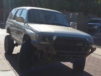
In addition to all of this, I got $57 dollar light bar, 32" 180watts, I plasma cut a hole and mounted it in my bumper, should look clean once I finish the pocket for it. also the bumper needs to come off and you need 3 wierd allen keys to remove it, so it probably wont get stolen. anyways its bright as hell.

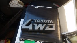
I also got chevy blazer bump stops, I cant say how I like them, but they are longer than stock and softer too haha. $2 a piece. also got the emblem off an 80s 4wd Tercel thats going to go into my grille. It looks bad ass and Says 4WD in big letters.
 

Attachments

  • 20150610_174244.jpg
    20150610_174244.jpg
    138.9 KB · Views: 1,576
  • 20150612_003226.jpg
    20150612_003226.jpg
    129.5 KB · Views: 1,484
  • 20150612_013246.jpg
    20150612_013246.jpg
    131.6 KB · Views: 1,498
  • 20150612_032442.jpg
    20150612_032442.jpg
    138.7 KB · Views: 1,453
  • 20150612_043833.jpg
    20150612_043833.jpg
    134.9 KB · Views: 1,513
  • 20150612_053037.jpg
    20150612_053037.jpg
    138.3 KB · Views: 1,433
  • 20150612_084015.jpg
    20150612_084015.jpg
    132.4 KB · Views: 1,733
  • 20150612_165828.jpg
    20150612_165828.jpg
    128 KB · Views: 1,497
Quick jump to 35s and you're making me jealous. Looking good man, any plans on gears?

I have 3.93 gears.

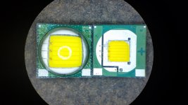
Still waiting for my wheel spacers, last night absalom dedomed his 40w led spots and said they came out awesome. if you dont know what dedoming is, this is a brief explanation. the throw(light concentration) of many offroad led products suffer. the leds come with a dome of silicone on them that helps to boost the light output by capturing the light from many angles, however it also spreads the point from the light is coming from. in almost all light setups the smaller your light source, the more concentrated your light output is. If you remove the dome the die is exposed and the surface area from which the light is emitted is much smaller. since the area is smaller and the light is more concentrated your beam is brighter and smaller, so it goes much farther.

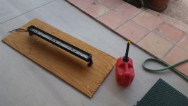
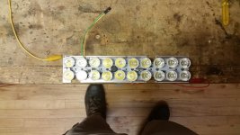
I recently bought a $57 180w led bar and im now in the process of dedoming it. I took it apart removed the reflectors and then set it up outside on a piece of wood. The dedoming process is pretty simple. I poured gasoline over the circuit boards and leds and lit it on fire, then I did a little dance and now im waiting until the sun god decides its time for the silicone domes to pop off. then ill flush it and my self with alcohol and test the output.
 

Attachments

  • 20150613_182718.jpg
    20150613_182718.jpg
    136.1 KB · Views: 1,454
  • 20150613_183218.jpg
    20150613_183218.jpg
    137.4 KB · Views: 1,407
  • 20150613_183811.jpg
    20150613_183811.jpg
    135.4 KB · Views: 1,447
well the sun gods werent happy, all the led wires broke. oh well time for an xml swap.

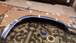
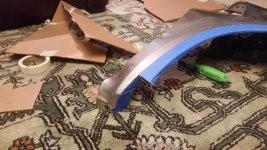
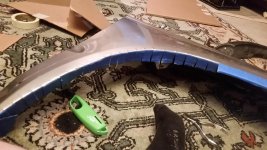
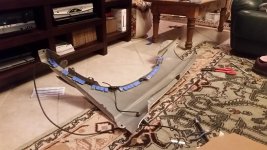
in other news, cut and fold. I used cardboard and made a template of the original lines on the fenders. Then I marked with tape with tape. I used the same shape and moved it back about an inch and about two up. My flares will simply be moved up and back, I continued the angle of the end of the flare down and ended it at the same spot as where i cut the firewall. I started with narrow 3/4" cuts but wider 2" cuts worked just as well. I used sheet metal shears to make the cuts. Ideally you would use sheet metal bending pliers but the ones i had were made for shorter sheet metal, so I simply pulled the tabs over. I put a plastic water tube under neath and bent them over in order to form a radiused edge. the finish is not excellent, but Its much stronger than just cutting, I didnt have to weld and then repaint, and my flares fit over. the only thing you will notice is that there is a lot of room for a bit wheel to fit into.
 

Attachments

  • 20150614_173143.jpg
    20150614_173143.jpg
    141.6 KB · Views: 1,373
  • 20150614_173927.jpg
    20150614_173927.jpg
    139.3 KB · Views: 1,365
  • 20150614_180406.jpg
    20150614_180406.jpg
    143.2 KB · Views: 1,389
  • 20150614_183626.jpg
    20150614_183626.jpg
    140.7 KB · Views: 1,363
  • 20150614_193207.jpg
    20150614_193207.jpg
    140.2 KB · Views: 1,396
got it mounted back on the truck, and tweaked the flare a bit, ill have to get some custom mudflaps or something to fill in that gap on the bottom though. my bumper will be moving up as well in order to sit at the same level as the flare, which will give the tire more room, and me an even better approach angle.

now all thats left is to redo the flare mounts cut the front off of the fender and make a set of flare extensions.
 

Attachments

  • 20150614_201854.jpg
    20150614_201854.jpg
    113.5 KB · Views: 1,432
  • 20150612_053037.jpg
    20150612_053037.jpg
    138.3 KB · Views: 1,360
  • 20150614_202540.jpg
    20150614_202540.jpg
    120.7 KB · Views: 2,801
put one on and then went to get the rest.

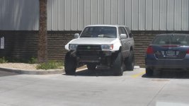
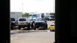
also saw this guy again, its a long travel desert dune 4runner, I left him my card so hopefully hell contact me or something so we can go wheeling.
 

Attachments

  • 20150615_165552-1.jpg
    20150615_165552-1.jpg
    126.3 KB · Views: 1,403
  • 20150615_181116-1.jpg
    20150615_181116-1.jpg
    130.8 KB · Views: 1,324
  • 20150615_114402.jpg
    20150615_114402.jpg
    131.6 KB · Views: 1,402
Went wheeling last night and figured out where I was rubbing, the passengerbside that I tubbed was perfect, the drivers side needs some work. the rear needs to be trimmed as well, but its not actually too bad, just rubs when flexing.

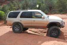
anyways Absalom pointed out to me last night that i wasnt all that excited to have these new awesome 35s, but the truth is that they dont have as many downside as you would think, they are smooth and handle well and do what I want, and I dont have to worry about anything hitting the underside of my truck haha. we also didnt do any rock crawling as thats not his style, he likes to go fast. They did well in the sand, we were going 30 on my speedo through most of the wash, which means about 40ish and they floated over the sand. I think I need to air down more though since the surface area has increased and also they are thicker tires.
 
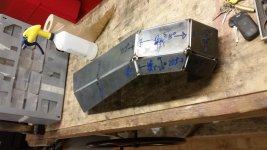
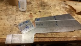
finished my tapered body lift, next is to make a new strong mount for the front bumper and also just finish it and paint it. in the meanwhile ive got my rear wings cut finally. I also beveled each peice before hand so each weld has a perfect 90 degree channel to weld into. its like a welders wet dream haha.

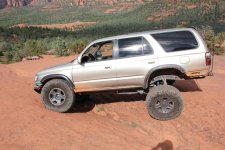
Ive also been playing around with the bump stops in the front, and I have shortened them, I cut enough to fit 35s without rubbing, and then added my tapered body lift which gave me about 2.6" more room for up travel, absalom gave me a set of poly bumps, which I then shortened a bit and installed. I did put the small stock bumpstop on the back of the arm though and it still allowed for the extended travel. so far no issues with the geometry or even bottoming out the tundra 5100 shock, I noticed that it had an entire inch that was left unused previous to doing this.

here are a couple videos, the first one is a 2-3 foot bump about 50mph(not sure wasnt looking that close at the spedo. the second is some articulating down a hill. I also have no sway bars, but im thinking about replacing the one on the back to force the front to articulate more.


Attachments

  • 20150712_215835.jpg
    20150712_215835.jpg
    135.3 KB · Views: 1,364
  • 20150712_205548.jpg
    20150712_205548.jpg
    131.2 KB · Views: 1,336
  • 20150712_181909.jpg
    20150712_181909.jpg
    142.1 KB · Views: 1,263
  • 20150711_171108.jpg
    20150711_171108.jpg
    127.8 KB · Views: 1,321
  • 20150711_143828.jpg
    20150711_143828.jpg
    129.1 KB · Views: 1,346
  • 20150711_052715.jpg
    20150711_052715.jpg
    138.3 KB · Views: 1,274
I have no need for 35's but damn does this make me want a set. Starting to really shape up, cant wait to see this thing with some painted bumpers.
 
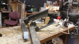
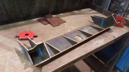
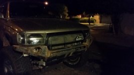
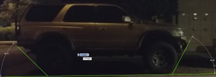
very close to finalizing the front, and the back is basically done except for welding a few things together, the tire swing out will come together later. I made a new better mount for the front that has reinforcement ribs, and a short hitch receiver. the mount basically goes right on the bottom plate of the bumper and in order to increase the approach angle I chopped the frame back to the welds for the body mount. another nifty thing about the body lift is that it lifted the radiator up so instead of hanging out 3.5" below the frame it hangs just a half inch below, and that allows me to basically not need a big ass skid plate, I can make a much more low profile streamlined one. the approach angle is about 60 degrees, and departure angle is 45 degrees. also I got rid of the top bar since it was interfering with my headlights and would probably damage them in a collision. another thing I did was finish chopping the front fenders so now the bumper comes all the way up to the lights.
 

Attachments

  • 20150719_105438.jpg
    20150719_105438.jpg
    136 KB · Views: 1,210
  • IMG_3739.jpg
    IMG_3739.jpg
    141.4 KB · Views: 1,354
  • IMG_3762.jpg
    IMG_3762.jpg
    139.9 KB · Views: 1,198
  • IMG_3765.jpg
    IMG_3765.jpg
    139 KB · Views: 1,197
  • 20150723_005004.jpg
    20150723_005004.jpg
    141.1 KB · Views: 1,180
  • 20150724_190842.jpg
    20150724_190842.jpg
    132 KB · Views: 1,222
  • 20150730_025618.jpg
    20150730_025618.jpg
    130 KB · Views: 1,228
  • approach angle.jpg
    approach angle.jpg
    118.5 KB · Views: 1,215
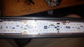
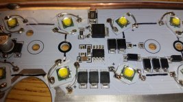
finally moving forward on the lightbar build. I ruined all of the previous leds, but a buddy of mine gave me a fe cree xml 10w leds. obviously they werent a direct plug and play fit. I ordered 16mm aluminum pads to mount the leds onto. the next issue was fitting the small pads onto the original circuit. I had to cut each pad down, then use a thermal epoxy to attach them to the main board. then I used stripped solid core wire and soldered one end to the board and one end to the pad. using a power supply at the lab I fired it up and it worked. with the new leds all on it pulled about 35 watts(200w worth of leds), which is strange. both leds are white and should have been pulling the same ammount of wattage, im not sure what this means about the original leds but I was able to find the resistor that limits the current, its 0.056 ohms. so i. order to get the wattage where I want it it needs to be I need to replace it with a 0.01 resistor to get approximately 200 watts of power running through.

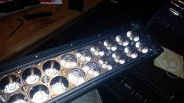
the next thing to tackle was optics. the main issue with the majority of the chinese led bars is the optics arent correct for the leds. the optics that came on the light bar were supposedly a 20° spot, and on the side 40° floods. unfortunately the optics were designed for the type of 5mm round leds found at radioshack for $1.99 each. any high powered led is a low profile half dome, the dome needs to be inside of the parabola to work correctly, with the way they old reflectors were, the the reflectors were positioned too far in front of the leds, and even if they wanted too, the reflector hole wasnt big enough to fit the led at all. after retrofitting the xml's I trimmed down the reflector to fit and it did actually work, however instead of filling up the whole reflector it made a ring, so it wasnt going to be efficient.
way back when I was making my own optics for my led plates(now used as leds work lights) I had discovered a new type of optic that collimates light and has a high efficiency. Its called total internal reflection or tir for short. in optics theres a thing called refractive index, this is the angle at which light is no longer transmitted through the medium and is instead reflected. using this optical property a lens can also be used as a reflector.

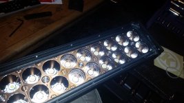
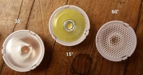
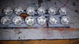
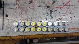
after discovering this I laser cut some 2d tir lenses and found that they worked nicely on some smaller flat leds. on ebay I found a company thats makes them for the xml's at around $0.50 each. I ordered 90 15° lenses 10 60° lenses and 5 30° lenses. they are all the same shape on the rear but the 30° has a fine microlens array on the front, and the 60° has a slightly corser microlens array, while the 15° was totally clear. as you can see in the picture the 15° lens is full of yellow, and that is good. Ill post more pictures of the output when I get to the lab.

Im so excited, as far as I know this is will be the highest power light bar that I know of at 600 watts, and the cree xml's are rated at 120 lumens per watt, and its using excellent optics that are %93 efficient. did I mention its only a 30" bar as well.
 

Attachments

  • 2015-08-08 16.07.49.jpg
    2015-08-08 16.07.49.jpg
    140.2 KB · Views: 1,146
  • 20150806_200857.jpg
    20150806_200857.jpg
    133.6 KB · Views: 1,198
  • 20150715_233141.jpg
    20150715_233141.jpg
    127.7 KB · Views: 1,200
  • 20150613_182718.jpg
    20150613_182718.jpg
    136.1 KB · Views: 1,150
Ok so I finally figured out why the board wasnt giving the leds enough juice. the inductor was limiting the ammount of current. basically the driver board is simply a buck driver that reduces voltage and increases the current. so in order to trick the driver i needed to do a couple of things. first I had to reduce the resistance of the resistor on the current sense pin, it was 0.056 which gave me 2.5 amps, I want to pull about 10 amps to give me about 130-140watts of total power usage. I needed a resistor that was approximately 0.01 ohms total. after looking for a while with no results I realized that a length of magnet wire would serve as a low ohm resistor. with 26 gauge that number was 2.5" of wire haha. so I wired it up and it was only pulling 6.5 amps, then I realized that the wire in the inductor was resisting the larger current draw. I did a bit of research and then found an old power supply with a ferrite core, then I took some thick magnet wire and wound it to replace the existing core. I wired it in and now I was at about 10 amps. I also placed the spot lenses on and they work perfectly, they have a nice hotspot with a bit of spill, no need for flood lenses at all. next is to secure the magnet wire resistor and find a spot to fit the new inductor. then ill mount the lenses and temporarily seal it all back up to test out.

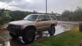
rained again the other day, also moved to a place with a nice long driveway to work on my truck.

here is a video of the output, I have the light of my phone on the entire time.
 

Attachments

  • 20150809_015144.jpg
    20150809_015144.jpg
    135.3 KB · Views: 1,190
  • 20150809_025413.jpg
    20150809_025413.jpg
    141.4 KB · Views: 1,130
  • 20150807_181049.jpg
    20150807_181049.jpg
    137.4 KB · Views: 1,140
Last edited:
I've driven up and down that exact spot at Butcher. I lifted a tire too lol.

the spot in the video you mean? I didnt lift at all haha, my rig is sort of sketch on the highway though man, I need to make some sort of sway bar system of the back that can be quick disconnect and tucked out of the way.
 
Video yeah, I thought the guy in the video said, "yeah" when asked if a tire was lifted lol. Maybe I heard wrong.
 
Video yeah, I thought the guy in the video said, "yeah" when asked if a tire was lifted lol. Maybe I heard wrong.

oh haha, it must have been when that front tire was compressed all the way.

man I missed out on a craigslist deal big time last weekend, a set of fron and rear 4.88s with a locker for $450, it would have probably paid itself off in gas mileage in a year.

do you lift here as well

 
Last edited:
oh haha, it must have been when that front tire was compressed all the way.

man I missed out on a craigslist deal big time last weekend, a set of fron and rear 4.88s with a locker for $450, it would have probably paid itself off in gas mileage in a year.

do you lift here as well


That would have been a nice grab! Not sure about there, that is a different spot right? Looks different from that angle at least lol.
 
That would have been a nice grab! Not sure about there, that is a different spot right? Looks different from that angle at least lol.

this is coming into the second cove, at the time I had a 3" body lift, which I have now taper to just 3 in the front and zero in the back.
 
Not sure about that one. I'll have to go back and find it and report back lol.

I have a body lift that is a bit over 1/2 an inch I still need to put on. Vehicle looks good, keep it up!
 
tucked in the wire resistor, and made a slightly more compact high amperage inductor. also hot glued the reflectors for now, just needs power and ill seal it and test it.
 

Attachments

  • 20150810_004818.jpg
    20150810_004818.jpg
    141.3 KB · Views: 1,101
  • 20150810_004917.jpg
    20150810_004917.jpg
    143.3 KB · Views: 1,118

Members online

Forum statistics

Threads
278,312
Messages
3,554,085
Members
248,016
Latest member
Advally Service

Trending content

Back
Top