
You are using an out of date browser. It may not display this or other websites correctly.
You should upgrade or use an alternative browser.
You should upgrade or use an alternative browser.
D Farms' Build thread: "Goldilocks"
- Thread starter D Farms
- Start date



D Farms
New member
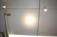
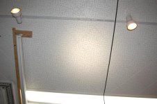
Well after last night I decided to dedome all of the leds. they still have a good ammount of spill but the hot spot is much much better and more yellow. after a few calculations, the dedomed led has a hotspot of about 7.5 degrees, compared to the 15 degrees of the domed led.
Attachments
D Farms
New member
finally got ahold of a rear locked axle. its a 4.30 ratio, which for now will be close enough to my 3.90s since I have awd. it has a bit of surface rust and is in rough shape but worst case scenario I just modify my stock axle to fit it. it ended up being 350, and the guy offered to buy my old axle back when im done.
does anyone have a link for info on swapping just the third member? this axle housing is kind of crappy and id rather just modify my existing housing.
does anyone have a link for info on swapping just the third member? this axle housing is kind of crappy and id rather just modify my existing housing.
Last edited:
D Farms
New member
Tested the light bar finally. here is a comparison between 20" of the 30" lightbar and my headlights. on saturday night [MENTION=116114]cf_coder[/MENTION] [MENTION=122900]AZBub[/MENTION] and I did a night run of box canyon, in record time I might add, I left at 7:00 and was back at 11:30, and I live in tempe. the light bar was working great at first, but I had really not tested the long term stability of it at all. one board worked it self loose quickly enough that there was no damage. on the other board, an led on each string managed to desolder itself because it was getting so hot. after taking it apart, I found that there wasnt very much thermal paste, and the mating surface of the heatsink was covered in clear powdercoat, which prevented the heatsink from absorbing the heat coming from the leds.
I have that landcruiser transmission cooler sitting around, and I have a few water pumps as well. I had joked to some of my friends that I would need to water cool this thing, and maybe I really do.
I have that landcruiser transmission cooler sitting around, and I have a few water pumps as well. I had joked to some of my friends that I would need to water cool this thing, and maybe I really do.
Attachments


D Farms
New member
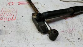
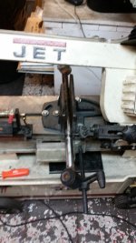
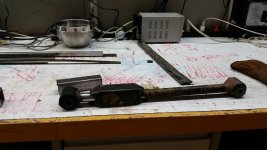
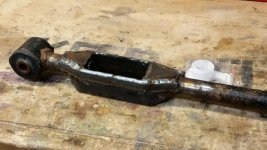
Modifying an beefing up some lower links. The main goal here is to make it stronger than stock, but still be able to have it accept the shock. Ive come to the conclusion that you would have to have 500lbs of extra stuff in the back to get any sort of landcruiser shock to feel right. The shock mounts directly to the control arm, 1/4 of the length away from the axle mount. there are a couple advantages that I get from this, first it takes my 9" tokico lc shock and makes it inline vertically with the axle, and when the shock travels 9" the axle travels 12". the second advantage is the shock will be softer now by a factor of about 25%.
Heres basically what I did:
cut the link 5.75" from the center of the bushing.
Plasma cut a 2x2" tube out and hammer the ends to make the cup
weld the cup together and cut the holes for the link to fit.
put the link through the tube, then tack weld back together.
line the cup up on the link, and weld it in place
cut the 2x2 tube open on the top
cut the remainer of the link out
weld the reinforcment strips on the sides
mill out the pocket so its clean.
mill the holes for the shock to bolt through.
thats it for now, later I will add more metal to the entire length of the link.
Heres basically what I did:
cut the link 5.75" from the center of the bushing.
Plasma cut a 2x2" tube out and hammer the ends to make the cup
weld the cup together and cut the holes for the link to fit.
put the link through the tube, then tack weld back together.
line the cup up on the link, and weld it in place
cut the 2x2 tube open on the top
cut the remainer of the link out
weld the reinforcment strips on the sides
mill out the pocket so its clean.
mill the holes for the shock to bolt through.
thats it for now, later I will add more metal to the entire length of the link.
Attachments
D Farms
New member
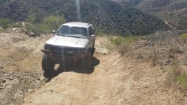
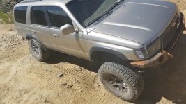
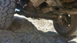
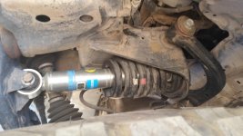
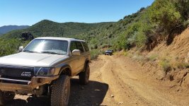
Did the back road to crown king, did all of the obstacles, except one where I knew I would need rock sliders.
Before the trip I had a huge fiasco with my engine coolant. My truck came from the factory with Toyota red coolant, at some point the radiator was changed out. I opened the top of my radiator and the fluid looked greenish but dirty. So I drained it, and it looked red. Then I decided to do a heavy duty flush and filled it with prestone coolant, the new formula. Apparently the old formula would cause sludge to form if mixed with the Toyota red coolant.
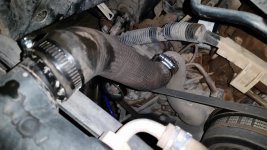
I also shortened the lower hose since it was kinked after the body lift, all I had to do was cut it and reattach.
Before the trip I had a huge fiasco with my engine coolant. My truck came from the factory with Toyota red coolant, at some point the radiator was changed out. I opened the top of my radiator and the fluid looked greenish but dirty. So I drained it, and it looked red. Then I decided to do a heavy duty flush and filled it with prestone coolant, the new formula. Apparently the old formula would cause sludge to form if mixed with the Toyota red coolant.
I also shortened the lower hose since it was kinked after the body lift, all I had to do was cut it and reattach.
Attachments

snivilous
Senior Member
Make sure your shock mounts below the centerline of the link, or otherwise has a wobble stop feature. I also assume you did at least a basic stress analysis to know the link is strong enough to handle the shock forces? Since obviously the link isn't designed to handle that much of a perpendicular load from it's nominal load vector, I would be worried that the huge moment at the root of the shock mount could bend/snap the link.
D Farms
New member
Make sure your shock mounts below the centerline of the link, or otherwise has a wobble stop feature. I also assume you did at least a basic stress analysis to know the link is strong enough to handle the shock forces? Since obviously the link isn't designed to handle that much of a perpendicular load from it's nominal load vector, I would be worried that the huge moment at the root of the shock mount could bend/snap the link.
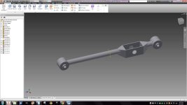
I haven't finished reinforcing it yet, but the idea was to use a thick angle iron along the entire length to increase the stiffness and make sure it won't yeild. The bolt hole is centered in the square, but the square hangs low on purpose to prevent the shock from trying to twist the link. I'll post my car model later, and the fea.
Attachments
Last edited:
D Farms
New member
What's loads are you using out of curiosity?
The best way I can think of getting the amount of force would be to calculate the downward speed of the truck if it were to fall from a certain difference.
I would never jump my truck more than 3 ft and the rear suspension will be about 12" of travel so I'll use 4ft as an example.
Let's say my truck weighs about 4500lbs.
When my truck hits the ground something has to give, obviously the suspension will cushion the impact, however for this situation lets assume that the suspension is fully compressed at the bump stop and that only one tire impacts. The tire will compress a certain amount upon impact. Let's say 4"
To determine the force we use the old physics 1/2at² equation. First we need to find the speed of the truck.
x=x0+v0t+½at²
0=4+½(32.2)t² t=√(8/32.2)=1 seconds so thats 8 ft per second. well plug that into our second equation.
x=x0+Vav*T
0=1/3+(8+0)/2*T T=0.166
0=1/3+½a(0.166)² a=144*2/3=23ft/s²
the mass of my truck is 4500lb/32.2ft/s²=140slugs
so the force would be 140*76=3220lb+4500lb
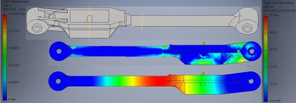
so about 7,720*4/3= about 10,000lb and id like a safety factor of about 2 if possible. feel free to check my math and also change any of the numbers. another thing is that the force would be much less if you consider that the suspension compresses 9" and the bump stops and rubber bushings also compress as well. also if it hit only one tire it would flex while compressing adding even more travel to that.
Last edited:
snivilous
Senior Member
That's interesting you have a stress spike there. Does your long hand analysis match the FEA in those peak stress areas? I don't understand why you would have so much stress near the joint where your moment is going to zero, unless I'm just not understand what the cross section is like right there.
D Farms
New member
That's interesting you have a stress spike there. Does your long hand analysis match the FEA in those peak stress areas? I don't understand why you would have so much stress near the joint where your moment is going to zero, unless I'm just not understand what the cross section is like right there.
I think it just has a lot more leverage over it right there. the other joint is just farther away. let me see if i can make the bolt fixed and apply force on the ends of the link instead.
edit: the constraints werent properly set, I fixed it
Last edited:
snivilous
Senior Member
I would pin the shock bolt hole and the frame mount, and then apply the 5000lbf at the axle mount location and that should be all you do for the FEA. That's why I asked about the long hand, at work we check everything with 3x different methods especially since FEA is so easy to screw up and you can just look at it and know that you have a 1st order moment curve that's a triangle and since stress =MC/I that means your stress is linearly decreasing (assuming the section is constant obviously)--and your FEA didn't match that.
D Farms
New member
I would pin the shock bolt hole and the frame mount, and then apply the 5000lbf at the axle mount location and that should be all you do for the FEA. That's why I asked about the long hand, at work we check everything with 3x different methods especially since FEA is so easy to screw up and you can just look at it and know that you have a 1st order moment curve that's a triangle and since stress =MC/I that means your stress is linearly decreasing (assuming the section is constant obviously)--and your FEA didn't match that.
interesting, ill have to mess with it some more later.

1985taylor1925
Senior Member
I see your logic with the shocks. I run lc rear shocks and they are too stiff with no added weight.
With the angle you are putting on them, wont the shocks (at the bottom where mounted to the a arms) swivel forward as the rear is compressed? Im trying to get a visual. In that case leverage will actually make the shock softers toward the bottom of compression. Or maybe Im visualizing too much angle on the shocks?
With the angle you are putting on them, wont the shocks (at the bottom where mounted to the a arms) swivel forward as the rear is compressed? Im trying to get a visual. In that case leverage will actually make the shock softers toward the bottom of compression. Or maybe Im visualizing too much angle on the shocks?
snivilous
Senior Member
I think what [MENTION=56756]1985taylor1925[/MENTION] is saying is that with the stock mounts the shock is angled forward which will give you an efficiency knock down as well. You want your shocks moving towards parallel with the direction of motion so they'll get "more efficient" as the suspension compresses (assuming you want that, that would be the same thing as progressive valving but from a geometry perspective). If the shock is angled forward to begin with it'll rotate forward as the axle bumps which will make it act softer as you compress more.
D Farms
New member
I think what [MENTION=56756]1985taylor1925[/MENTION] is saying is that with the stock mounts the shock is angled forward which will give you an efficiency knock down as well. You want your shocks moving towards parallel with the direction of motion so they'll get "more efficient" as the suspension compresses (assuming you want that, that would be the same thing as progressive valving but from a geometry perspective). If the shock is angled forward to begin with it'll rotate forward as the axle bumps which will make it act softer as you compress more.
I see, ill make a model, and see how the comparison is, the other thing is that the shock will be verticle from the left to right perspective now, instead of being angled. ill take a look under the truck and see what the angle is from front to back of stock and where it is on the new arm.
Similar threads

- Replies
- 2
- Views
- 3K
- Replies
- 2
- Views
- 2K


