
You are using an out of date browser. It may not display this or other websites correctly.
You should upgrade or use an alternative browser.
You should upgrade or use an alternative browser.
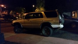
D Farms' Build thread: "Goldilocks"
- Thread starter D Farms
- Start date

theBEAR
New member
Hey [MENTION=100116]D Farms[/MENTION] First of all, I love the build. It looks great!
Did you install those yellow "running lights" during your headlight retrofit? I've been thinking about doing some wiring to have more control over my headlights. DRL might be more "safe" but I have never liked them. I want to do something similar to what you have done. I want the option of turning on my parking lights if I want heightened visibility.
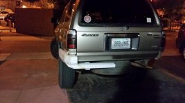
Secondly, all of us are DIYers on here, but every once in a while I finish a project and I think, "that was such a PITA! I should have paid someone else to do that . . ." Do you feel a sense of achievement after finishing your bumper or was it a "shoulda got an ARB" moment?
... judging by your rear bumper build in progress I think I know the answer to the question, but I wanted to get your thoughts. thanks
Did you install those yellow "running lights" during your headlight retrofit? I've been thinking about doing some wiring to have more control over my headlights. DRL might be more "safe" but I have never liked them. I want to do something similar to what you have done. I want the option of turning on my parking lights if I want heightened visibility.
Secondly, all of us are DIYers on here, but every once in a while I finish a project and I think, "that was such a PITA! I should have paid someone else to do that . . ." Do you feel a sense of achievement after finishing your bumper or was it a "shoulda got an ARB" moment?
... judging by your rear bumper build in progress I think I know the answer to the question, but I wanted to get your thoughts. thanks

D Farms
New member
Hey [MENTION=100116]D Farms[/MENTION] First of all, I love the build. It looks great!
Did you install those yellow "running lights" during your headlight retrofit? I've been thinking about doing some wiring to have more control over my headlights. DRL might be more "safe" but I have never liked them. I want to do something similar to what you have done. I want the option of turning on my parking lights if I want heightened visibility.
Secondly, all of us are DIYers on here, but every once in a while I finish a project and I think, "that was such a PITA! I should have paid someone else to do that . . ." Do you feel a sense of achievement after finishing your bumper or was it a "shoulda got an ARB" moment?
... judging by your rear bumper build in progress I think I know the answer to the question, but I wanted to get your thoughts. thanks
Thanks!
I did the led lights recently, they arent bright enough on the amber setting during the day to be used as drls, the white setting is noticable. as far as my bumper, there were a few criteria that i went for while building it: excellent protection, good approach angle and looks that match my 4runner, pretty much none of the bumpers on the market were what i wanted, espescially not the arb which is made to crunch. plus it cost me significantly less than what an arb is. the bumper build was not a pain at all, putting in poly bushings in the steering rack without the right tools is a pain.
theBEAR
New member
Thanks!
I did the led lights recently, they arent bright enough on the amber setting during the day to be used as drls, the white setting is noticable. as far as my bumper, there were a few criteria that i went for while building it: excellent protection, good approach angle and looks that match my 4runner, pretty much none of the bumpers on the market were what i wanted, espescially not the arb which is made to crunch. plus it cost me significantly less than what an arb is. the bumper build was not a pain at all, putting in poly bushings in the steering rack without the right tools is a pain.
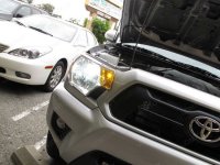
Oh, that is disappointing. The amber looks really cool! I've always loved the '12 Tacoma headlights and the parking lights look awesome to me. I'm thinking about a way to add some ambers bright enough to increase visibility during the day and in dusk/daybreak driving. Without looking like an ebay shopping cart, of course.
What level of skill do you need with a welder to do what you did with your bumper?
Here is a pic of a 2012 Tacoma headlight for your reference.
Attachments
D Farms
New member
This was really my first big project with a welder, but as ive heard and experienced, 90% of welding is preparation, cutting and grinding. I modeled it in the computer first, then made a mock up out of 3/16" foamcore cnc cut on a laser cutter at my hackerspace. then made sure it all fit. then i had the pattern water jetted out of 3/16" steel. the mig welder i used was only 140amps, so I tacked together all the plates and ground each joint to a u slot. then I welded it all up. so its not hard at all, but there is a lot of prep to do before you even do any welding, and if you dont have the right tools it will take a lot longer.
for my rear bumper im going to make the foam mock up again(already done) but im going to cut all the pieces with a 7" cutoff wheel and then use this grinding machine we have to make the edges perfectly flat. it will take longer but it will be cheaper since i cant get it water jetted this time for free.
for my rear bumper im going to make the foam mock up again(already done) but im going to cut all the pieces with a 7" cutoff wheel and then use this grinding machine we have to make the edges perfectly flat. it will take longer but it will be cheaper since i cant get it water jetted this time for free.
D Farms
New member
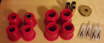
pretty much all the bushings in my front end that i havent replaced are toast. so i got this set of poly bushings for $45, which is good since they are poly.
heres the instructions http://www.lcengineering.com/LCInstructions/8481839 Energy.pdf
heres the instructions http://www.lcengineering.com/LCInstructions/8481839 Energy.pdf
Attachments
Last edited:

scrapper
New member
This was really my first big project with a welder, but as ive heard and experienced, 90% of welding is preparation, cutting and grinding. I modeled it in the computer first, then made a mock up out of 3/16" foamcore cnc cut on a laser cutter at my hackerspace. then made sure it all fit. then i had the pattern water jetted out of 3/16" steel. the mig welder i used was only 140amps, so I tacked together all the plates and ground each joint to a u slot. then I welded it all up. so its not hard at all, but there is a lot of prep to do before you even do any welding, and if you dont have the right tools it will take a lot longer.
for my rear bumper im going to make the foam mock up again(already done) but im going to cut all the pieces with a 7" cutoff wheel and then use this grinding machine we have to make the edges perfectly flat. it will take longer but it will be cheaper since i cant get it water jetted this time for free.
Very very impressive. I cannot believe you made that front bumper
and it looks as cool as any I've seen.
It is somewhat disheartening at the same time though.
I was sweating, bleeding, cursing myself into Hell and
banging chips of concrete out of my garage floor with
my bloody socket wrench in fury just taking off my stock running boards. Damn.

D Farms
New member
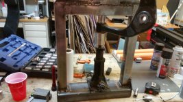
Thanks, I made my self a nice shop bench press, it uses this piece of shit jack I found for now.
heres my CAD drawing i made first.

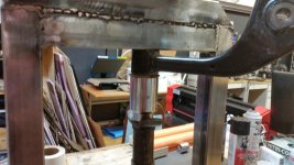
and then I made it, it accepts 1/2" impact gun.

and then i crushed a can for a test, and it worked!:sniper:

Thinking about making it hitch mountable.
heres my CAD drawing i made first.
and then I made it, it accepts 1/2" impact gun.
and then i crushed a can for a test, and it worked!:sniper:
Thinking about making it hitch mountable.
Last edited:
D Farms
New member
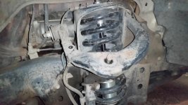
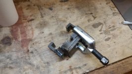
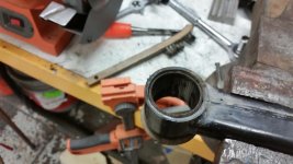
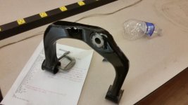
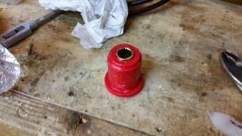
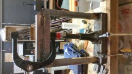
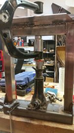
Ok well im having one hell of a time doing my uca bushings. first my puller broke, luckily im at the lab so i fabbed up an adapter to go over the uca and allow a pitman arm puller to be used that i had with me. finally got the arm out, the bolt was easy. then using the press i made yesterday i started on the bushings, which were actually in perfect condition so this is really just a big waste of time. With these poly bushings you leave the metal sleeve from the old bushings and remove the rubber. It says to take the whole bushing out, but I couldnt figure out a good way to do it with my press, plus they are probably seized in there anyways. so I actually just pressed the rubber out leaving the shells in. I used a 35mm socket(the one for the axle) underneath and put a 1inch socket on top of the rubber, then pressed the rubber out. there was some residual rubber, so i used some screw drivers a chisel and wire brush to get rid of the extra rubber. If you are thinking about doing this you could also use a hot knife cutter to scrape the rubber out. so far the rubber removal was actually the easiest part of this project. when i was pressing them out, they kind of made this noise and, I could tell, that's when they gave up.
man now im thinking i should have kept them in, they gave me so much more flex on the trail.https://plus.google.com/u/0/photos/112866749432716540184/albums/6139406964219068273/6139406965681272818
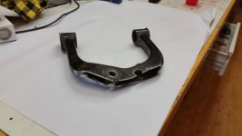
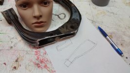
while i was at it I "shaved" my UCAs using steve shafers pictures as my model. I just made the cuts and figured id write this while waiting for the uca to cool down so i can trace the shape of the cut for the filler piece of metal.
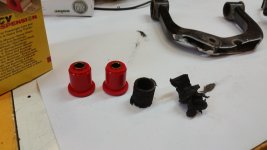
also old vs new bushings.
man now im thinking i should have kept them in, they gave me so much more flex on the trail.https://plus.google.com/u/0/photos/112866749432716540184/albums/6139406964219068273/6139406965681272818
while i was at it I "shaved" my UCAs using steve shafers pictures as my model. I just made the cuts and figured id write this while waiting for the uca to cool down so i can trace the shape of the cut for the filler piece of metal.
also old vs new bushings.
Attachments
-
 20150418_225829.jpg133.8 KB · Views: 1,522
 -
 20150419_012835.jpg130.1 KB · Views: 1,429
 -
 20150419_020908.jpg138.8 KB · Views: 1,457
 -
 20150419_021238.jpg135.2 KB · Views: 1,433
 -
 20150419_023348.jpg129.8 KB · Views: 1,411
 -
 20150419_035040.jpg112.2 KB · Views: 1,418
 -
 20150419_041333.jpg116 KB · Views: 1,430
Last edited:
D Farms
New member
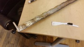
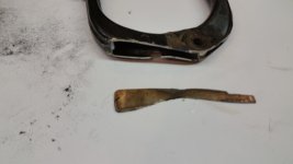
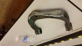
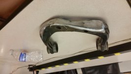
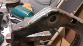
Alright waiting for the paint to dry. After i cut the uca using a cutoff wheel, I used this jet flat grinder we have at the lab to make the cut flat, then I traced the shape of the cut and by hand removed an 1/8" of material then cut it out and transfered the pattern to steel. went back to the welding booth and used the cutoff wheel to get the rough shape, then finished it off with the jet grinder. then I tacked it in place on one side, and beat it with a hammer to go around the curve, then clamped it the rest of the way down and tacked it. then i welded it all the way around. after than i used a 7 inch grinder with a flap wheel to smooth it all out, what i did looks better than the what the oem part does. then just a couple coats of gloss black.
ill post back in a few after I press the bushings in.
ill post back in a few after I press the bushings in.
Attachments
D Farms
New member
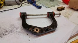
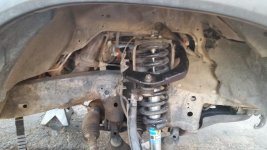
All done modifying the uca and its painted now. I greased the poly bushings and pushed them in on the press, then bolted it back in to the truck, just need to put the wheel on, and do the other side and both lowers. oh yeah the little plug fit back in too!
Attachments
Last edited:
D Farms
New member
D Farms
New member
[MENTION=75445]4Running Daily[/MENTION] came over to the lab and helped me do the bottom bushings. the main difference was getting the arm off required ubolting and moving the steering rack, and also unbolting the drivers side diff drop and loosening the passenger side diff. You actually have to dissasmble the bushing. basically there is an outershell, which stays in. and an inner sleeve that has washers on each end.
to better explain this inner sleeve, the end of the sleeve... ****it ill draw it in cad.
anways the thin end part is put through the washer and then mushroomed over to keep it on.
In order to put the new bushing on, one washer needs to come off. I picked the smaller one because my pitman arm puller fit over it. it was a tight fit, then i found a machine bolt that fit in the end of the sleeve but didnt cover the washer. i also put a nut between the screw of the puller and the bolt head. the washers get bent but they are strong and can be bent back, the flatness is not important to the operation of the bushing.
then we took the arm outside and heated it up with the torch focusing most of the heat on where the sleeve was attached to the arm. you can kind of hear the bushing start popping and crackling, keep the heat on a little longer then grab the sleeve with pliers and it should pull out, if it doesnt heat it longer. use the torch on the inside of the sleeve. once the rubber starts crackling use something disposable to scrape it off. we discovered that a piece of scrap steel works best and have now patented the idea, we call it "metal thing".
then chuck it in the vice and use a wire wheel on a drill to remove the excess rubber from the inner and outer sleeve. take the sleever and use the vice to fold the metal that was holding the washer back in so the washer will fit over it, use the washer to check, it doesnt need to be perfect, if its close a tap of the hammer will finish the job.
grease the new poly bushings and press it all together. if you dont have a press, get creative with your bottle jack, use your bumper, use a metal chair, whatever works. now put the washer on and use a ball pein hammer the mushroom the sleeve metal over the washer, i didnt have a ball pein so i used a blunt chisel and hammer.
now the arm is done and can be bolted in.
I also noticed that my control arm mount had taken a hit, but it seemed to fit back in ok.
to better explain this inner sleeve, the end of the sleeve... ****it ill draw it in cad.
anways the thin end part is put through the washer and then mushroomed over to keep it on.
In order to put the new bushing on, one washer needs to come off. I picked the smaller one because my pitman arm puller fit over it. it was a tight fit, then i found a machine bolt that fit in the end of the sleeve but didnt cover the washer. i also put a nut between the screw of the puller and the bolt head. the washers get bent but they are strong and can be bent back, the flatness is not important to the operation of the bushing.
then we took the arm outside and heated it up with the torch focusing most of the heat on where the sleeve was attached to the arm. you can kind of hear the bushing start popping and crackling, keep the heat on a little longer then grab the sleeve with pliers and it should pull out, if it doesnt heat it longer. use the torch on the inside of the sleeve. once the rubber starts crackling use something disposable to scrape it off. we discovered that a piece of scrap steel works best and have now patented the idea, we call it "metal thing".
then chuck it in the vice and use a wire wheel on a drill to remove the excess rubber from the inner and outer sleeve. take the sleever and use the vice to fold the metal that was holding the washer back in so the washer will fit over it, use the washer to check, it doesnt need to be perfect, if its close a tap of the hammer will finish the job.
grease the new poly bushings and press it all together. if you dont have a press, get creative with your bottle jack, use your bumper, use a metal chair, whatever works. now put the washer on and use a ball pein hammer the mushroom the sleeve metal over the washer, i didnt have a ball pein so i used a blunt chisel and hammer.
now the arm is done and can be bolted in.
I also noticed that my control arm mount had taken a hit, but it seemed to fit back in ok.
Last edited:
D Farms
New member
Now that you have it all back, dont put the skid back on just yet, put everything else back and drive it for a few feet and make a turn or two.
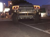
this is how my truck looked afterwards, and i did align everything back to where it was.
so why was it so bad? the bushings were so bad the alignment shop had to over compensate to get it to have the correct alignment.
I could not even drive it a straight line, it felt like i was driving with a locked front diff with a 35 on one side and 28 on the other haha. the tires were pointing in at eachother and the tires tilted inwards on the bottom.
so i put down some old floor mats with the spikes down, and another on top with the spikes up, then reversed on to them, just for the front. using a measuring tape and my eyeballs i adjusted the cams first then adjusted the tie rods.
I got it pretty close, and it felt good enough to drive home and drive to the alignment shop.
this is how my truck looked afterwards, and i did align everything back to where it was.
so why was it so bad? the bushings were so bad the alignment shop had to over compensate to get it to have the correct alignment.
I could not even drive it a straight line, it felt like i was driving with a locked front diff with a 35 on one side and 28 on the other haha. the tires were pointing in at eachother and the tires tilted inwards on the bottom.
so i put down some old floor mats with the spikes down, and another on top with the spikes up, then reversed on to them, just for the front. using a measuring tape and my eyeballs i adjusted the cams first then adjusted the tie rods.
I got it pretty close, and it felt good enough to drive home and drive to the alignment shop.
Attachments
Similar threads

- Replies
- 2
- Views
- 3K
- Replies
- 2
- Views
- 2K


