
You are using an out of date browser. It may not display this or other websites correctly.
You should upgrade or use an alternative browser.
You should upgrade or use an alternative browser.
DRL and Turn Signal Mods.
- Thread starter J.A.
- Start date
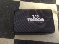
buyer beware VLEDS
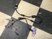
2. I put the harness together to see if everything was functioning
properly. As you can see, I took the DLR light harness out
to wire up the LEDS to the lower DLR light source. This allowed
the VLEDS to light up even when truck isn't running.
2. I put the harness together to see if everything was functioning
properly. As you can see, I took the DLR light harness out
to wire up the LEDS to the lower DLR light source. This allowed
the VLEDS to light up even when truck isn't running.
Attachments
Last edited:
Buyer beware VLEDS
3. I noticed that the connection to the bulb socket was very loose. So I figured since it is suppose to be a "Dry" component, I wrapped it in tape to keep the elements out. And this was done to make a more secure connection. There is nothing more frustrating than having a New Mod fail.
3. I noticed that the connection to the bulb socket was very loose. So I figured since it is suppose to be a "Dry" component, I wrapped it in tape to keep the elements out. And this was done to make a more secure connection. There is nothing more frustrating than having a New Mod fail.
Attachments
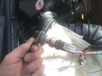
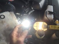
4. During installation I kept testing the system by turning it on to see
if there were any problems. This turned out to be a good policy
here.
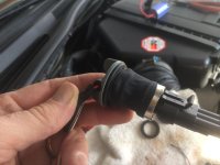
I noticed that the shaft of the LED was a little loose in the collar/
heat sink thingys. They serve a purpose to allow the light to be adjusted
in the reflector.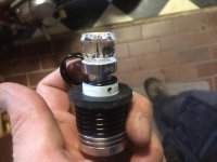
The reflector should be dry so as not to get that fish bowl effect
(MOISTURE). So I used 3-4 layers of Teflon tape. It also tightened
the bulb assembly.
Here is my first complaint about the product. IT SHOULD ALREADY
BE WATER TIGHT. I didn't test it, but I was certain moisture would
have gotten through without modification.
if there were any problems. This turned out to be a good policy
here.
I noticed that the shaft of the LED was a little loose in the collar/
heat sink thingys. They serve a purpose to allow the light to be adjusted
in the reflector.
The reflector should be dry so as not to get that fish bowl effect
(MOISTURE). So I used 3-4 layers of Teflon tape. It also tightened
the bulb assembly.
Here is my first complaint about the product. IT SHOULD ALREADY
BE WATER TIGHT. I didn't test it, but I was certain moisture would
have gotten through without modification.
Attachments

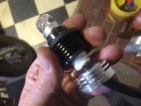
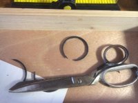
5. Now you will notice on the last photo, I had a rubber gasket on the
of the LED. I had tried the other socket gaskets that came in the kit.
There were two small gaskets; one thin, the other one thicker. And
two bigger gaskets; thick and thinner.
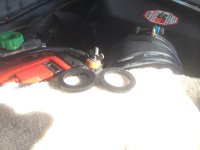
When I tried the smaller ones, I noticed light sneaking past the gaskets
while the light was installed. Not Good! If light can get through... so can
water.
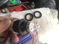
The bigger gaskets didn't fit the reflector either. I had to trim
the bigger thick gasket to make it work AND add lots of Teflon.
of the LED. I had tried the other socket gaskets that came in the kit.
There were two small gaskets; one thin, the other one thicker. And
two bigger gaskets; thick and thinner.
When I tried the smaller ones, I noticed light sneaking past the gaskets
while the light was installed. Not Good! If light can get through... so can
water.
The bigger gaskets didn't fit the reflector either. I had to trim
the bigger thick gasket to make it work AND add lots of Teflon.
Attachments
Buyer beware VLEDS
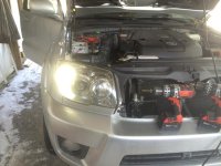
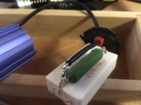
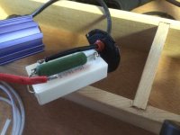
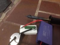
6. So I installed the light and ran it a bit. Tested the signals, high
beams, ....
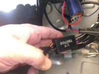
Then I noticed that the signals started flashing quickly. It was normal
at first. But after 10 minutes... the Resistor failed. :flamethrwoer2:
Brand new product... and now here I was trying to think through
this problem. (resistor provided additional wattage to the relay to
have the signal cycle properly... do I cut this thing out... try to
install a actual lamp for resistance.. uummm...
6. So I installed the light and ran it a bit. Tested the signals, high
beams, ....
Then I noticed that the signals started flashing quickly. It was normal
at first. But after 10 minutes... the Resistor failed. :flamethrwoer2:
Brand new product... and now here I was trying to think through
this problem. (resistor provided additional wattage to the relay to
have the signal cycle properly... do I cut this thing out... try to
install a actual lamp for resistance.. uummm...
Attachments
Buyer beware VLEDS
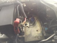 I put everything back together again and tried it. Surprisingly...
It worked. I let the resistor get hot and it held.
So now I pull apart the second resistor. It looks good... I thought...
so I began to install the second lamp on Batt side.
I repeat my lamp preparation and install. I test everything and
it works... well looks like it.... I think...
I put everything back together again and tried it. Surprisingly...It worked. I let the resistor get hot and it held.
So now I pull apart the second resistor. It looks good... I thought...
so I began to install the second lamp on Batt side.
I repeat my lamp preparation and install. I test everything and
it works... well looks like it.... I think...
Attachments

Last edited:
Buyer beware VLEDS
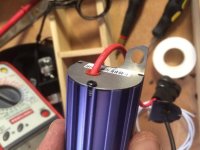
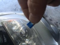
:roadkill::roadkill:It worked. I Put the Batt back. Drive a little.... btw... it was 15 degrees out ( Fahrenheit). So three hours
I'm done, I'm cold... I'm putting back my tools and I try my left signal one more time. It fails. :-(
The signals are both out. I check the 15 amp fuse and it's blown.
I then take out the tools. Take out the Battery. Take out the Resistor
and opened it up... the solder melted just like the other one. When it did
the positive wire grounded in the heat sink case.
So I remove the resistor. I solder it up again. I put it back. I install a new
mini fuse.
:roadkill::roadkill:It worked. I Put the Batt back. Drive a little.... btw... it was 15 degrees out ( Fahrenheit). So three hours
I'm done, I'm cold... I'm putting back my tools and I try my left signal one more time. It fails. :-(
The signals are both out. I check the 15 amp fuse and it's blown.
I then take out the tools. Take out the Battery. Take out the Resistor
and opened it up... the solder melted just like the other one. When it did
the positive wire grounded in the heat sink case.
So I remove the resistor. I solder it up again. I put it back. I install a new
mini fuse.
Attachments
Last edited:
Buyer beware VLEDS
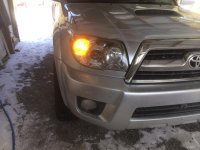
Finally it all works. The lights work and are bright. Ambers kick in
on signals as it should. I did not connect the dimmer wire, but
I am leaning towards wiring up a manual switch. I want to first
see how blinding these things are at night and see if a dimmer is
necessary.
I have driven around for a day it seems to be holding up. Not sure
if the reflectors are water tight. But I will know soon enough. If
I have to I will just keep adding Teflon until it can keep the water
out.
While I was impressed by the VLED light output, I was really
disappointed by the lack of quality with the resistors (at least
both resistors failed predicatively and consistently) and the
lack of a proper fit into the lamp housing. The plug in connection
with the socket output was unimpressive. There were no installation
instructions included either. You basically have to slide all the
connectors together and try to figure out what the extra blue wire
was for (it was a positive input for the DRL which could be spliced
into the headlight or the smaller DLR). This could be a Great
product, but it is the lack of attention to detail that makes
this product just above average. Unless you are well versed in
electrical knowledge and you have a lot of ingenuity, I would warn
most people to stay away from this kit.
I would be glad to answer any installation questions. I feel sorry
for some of you that have had to deal with the same aggravation
as I had.
Finally it all works. The lights work and are bright. Ambers kick in
on signals as it should. I did not connect the dimmer wire, but
I am leaning towards wiring up a manual switch. I want to first
see how blinding these things are at night and see if a dimmer is
necessary.
I have driven around for a day it seems to be holding up. Not sure
if the reflectors are water tight. But I will know soon enough. If
I have to I will just keep adding Teflon until it can keep the water
out.
While I was impressed by the VLED light output, I was really
disappointed by the lack of quality with the resistors (at least
both resistors failed predicatively and consistently) and the
lack of a proper fit into the lamp housing. The plug in connection
with the socket output was unimpressive. There were no installation
instructions included either. You basically have to slide all the
connectors together and try to figure out what the extra blue wire
was for (it was a positive input for the DRL which could be spliced
into the headlight or the smaller DLR). This could be a Great
product, but it is the lack of attention to detail that makes
this product just above average. Unless you are well versed in
electrical knowledge and you have a lot of ingenuity, I would warn
most people to stay away from this kit.
I would be glad to answer any installation questions. I feel sorry
for some of you that have had to deal with the same aggravation
as I had.
Attachments
Last edited:


CookieRoe
Senior Member
damn............
[MENTION=79761]Cycle M5[/MENTION] sorry to hear of your woes. Thanks for documenting your experience, but I would've returned them before soldering, trimming and whatever. I'm sure any "warranty" claim would be thrown out the door. In any event, good to see you got them working. Your experience is WAY different from mine. I had no installation issues and they continued to work flawlessly even when (a few threads ago) one popped out of the light assembly. It got soaked, frozen, etc and continued to work. I'm still happy with them and would recommend them to anyone.
Switchbacks (lots of chinese products) have been out for a while now, but most folks get them on fleabay. I still say vLeds make a quality product. I haven't seen a product that compares to them (in fact, I'm playing with the idea of getting their LMZ 4500LMN monsters for my hi beams). If there is a company that stands behind their product like they do, let us know!
Let us know how they hold up!
[MENTION=79761]Cycle M5[/MENTION] sorry to hear of your woes. Thanks for documenting your experience, but I would've returned them before soldering, trimming and whatever. I'm sure any "warranty" claim would be thrown out the door. In any event, good to see you got them working. Your experience is WAY different from mine. I had no installation issues and they continued to work flawlessly even when (a few threads ago) one popped out of the light assembly. It got soaked, frozen, etc and continued to work. I'm still happy with them and would recommend them to anyone.
Switchbacks (lots of chinese products) have been out for a while now, but most folks get them on fleabay. I still say vLeds make a quality product. I haven't seen a product that compares to them (in fact, I'm playing with the idea of getting their LMZ 4500LMN monsters for my hi beams). If there is a company that stands behind their product like they do, let us know!
Let us know how they hold up!

J.A.
Senior Member
Wow, that didnt sound good and I would have returned them as well. I am running the Gen2 kit but it looks like they moved to Gen2.5 now and they now appear to have external resistors. I'm not liking that at all, looks like a step backward. The Gen2 control box looks much nicer in all metal as well. Probably too late now but since they still sell the Gen2 control boxes separately perhaps you can get them to swap your out to the older style?
Buyer beware VLEDS
I still think these VLEDS are impressive. But it was the little headaches that took away from this product's mark of high quality.
I only took the resistors apart. The main led was not disassembled in any way. The large gasket would not fit, even when i tried to force it into the headlight assembly. I even tried 'dry fitting' the large gasket by itself with no light, and it was just a shade to big. If the inner diameter was a shade smaller, and the outer diameter was a shade smaller, and the washer was just a bit thicker... it would have worked. It almost seemed like when the LEDS were upgraded to 2.5, the sizes of the hardware shrank by a millimeter. The adapter collar didn't even fit that well. it had a decent sized gap between the LED and the adapter collar.
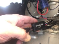
And the control box was not at all like the 2.0's that I saw on this thread. The wires come out of both ends of the box RIGHT where the screw tab was. It made it almost impossible to screw the things into the sheet metal.
I was half tempted to glue new tabs to the control box to mount it with. This was not very well thought out. The older style appeared to be better designed with both insulated wires coming out the bottom.
I may write to VLED and possibly let them know of these issues. I'm not looking for any discounts or special treatment... but it seems like somebody is not taking a close look at the product they are putting together. There should be some internal quality control at that business.
I still think these VLEDS are impressive. But it was the little headaches that took away from this product's mark of high quality.
I only took the resistors apart. The main led was not disassembled in any way. The large gasket would not fit, even when i tried to force it into the headlight assembly. I even tried 'dry fitting' the large gasket by itself with no light, and it was just a shade to big. If the inner diameter was a shade smaller, and the outer diameter was a shade smaller, and the washer was just a bit thicker... it would have worked. It almost seemed like when the LEDS were upgraded to 2.5, the sizes of the hardware shrank by a millimeter. The adapter collar didn't even fit that well. it had a decent sized gap between the LED and the adapter collar.
And the control box was not at all like the 2.0's that I saw on this thread. The wires come out of both ends of the box RIGHT where the screw tab was. It made it almost impossible to screw the things into the sheet metal.
I was half tempted to glue new tabs to the control box to mount it with. This was not very well thought out. The older style appeared to be better designed with both insulated wires coming out the bottom.
I may write to VLED and possibly let them know of these issues. I'm not looking for any discounts or special treatment... but it seems like somebody is not taking a close look at the product they are putting together. There should be some internal quality control at that business.
Attachments
OK,
I let VLEDS know of my experiences. Hopefully, they take a second look at this product and make some changes. Here was my letter.
"I had some problems installing your product. The control box was not as shown on your website. The collars did not really fit that well on the led emitter. There was no instructions included. The resistors failed in the first 10 minutes. The gasket rings (large one) did not fit my 08 Toyota 4 Runner. The LEDS did work and were very bright. but I spent a good 4 hours battling the other issues with the install. I'm a big fan of your products and I not asking for any refunds. I just thought you should know my experiences. For a more detail description of the issues, please see my post on the T4R forums; http://www.toyota-4runner.org/4th-gen-t4rs/170869-drl-turn-signal-mods-6.html#post1929754.
Thank you for your time, Andy"
I let VLEDS know of my experiences. Hopefully, they take a second look at this product and make some changes. Here was my letter.
"I had some problems installing your product. The control box was not as shown on your website. The collars did not really fit that well on the led emitter. There was no instructions included. The resistors failed in the first 10 minutes. The gasket rings (large one) did not fit my 08 Toyota 4 Runner. The LEDS did work and were very bright. but I spent a good 4 hours battling the other issues with the install. I'm a big fan of your products and I not asking for any refunds. I just thought you should know my experiences. For a more detail description of the issues, please see my post on the T4R forums; http://www.toyota-4runner.org/4th-gen-t4rs/170869-drl-turn-signal-mods-6.html#post1929754.
Thank you for your time, Andy"

Pathfinder5243
New member
Buyer beware VLEDS
Update:
So after two days the VLEDS are holding up well. Drove with them at night and they are super. They have not been in the rain yet so when it rains tomorrow, I will have more to report on if I have been able to keep out the moisture. The resistors that I soldered/repaired have not failed yet after three hours of driving. It has been cold here in the north east and that might be helping to keep the resistors cooler... maybe not.
The good people at VLEDS have contacted me and gave me some good advise about their product. I had mentioned that I used Teflon tape around the shaft of the LED under the heat sink. They advised me that this was not a good idea because this would keep heat from being transferred away from the LED.
I think this is wise advice. I realized this when I did it, but I read somewhere here that the lamp heat sink was not really necessary because it did not get very hot. I checked the heat sink after a couple hours of driving and they were pretty warm, but not bad. I can only guess that the heat is transferring through the very thin Teflon just fine. VLEDS also claims that the heat sink should keep the moisture out when the rear collar is tightened up. I will probably test this theory by taking off the Teflon on the passenger side lamp to see if it stays dry.
They also reported the large gaskets were the proper size that needed no trimming. I had tried to dry fit them after failing to install them mounted on the lamp, but it did not seat in the outside of the housing. Maybe I should have forced them in more... I'm not certain if that would have worked. The smaller gaskets did not really fit well. I could see light light escaping around the gasket. I'd like to hear what the experiences of others have been in this respect.
VLEDS also mentioned that they no longer use that resistor that was sent to me. That is good to hear, but unfortunately I must have gotten the last of that batch of the Morimoto Resistors. If anyone else here has had them fail, I can tell you that they can be re-soldered pretty easily. My recommendation would be to wrap the wires together well before soldering them with flux. They get WAY hotter than the LEDS.
I will have more on this product later.
Update:
So after two days the VLEDS are holding up well. Drove with them at night and they are super. They have not been in the rain yet so when it rains tomorrow, I will have more to report on if I have been able to keep out the moisture. The resistors that I soldered/repaired have not failed yet after three hours of driving. It has been cold here in the north east and that might be helping to keep the resistors cooler... maybe not.
The good people at VLEDS have contacted me and gave me some good advise about their product. I had mentioned that I used Teflon tape around the shaft of the LED under the heat sink. They advised me that this was not a good idea because this would keep heat from being transferred away from the LED.
I think this is wise advice. I realized this when I did it, but I read somewhere here that the lamp heat sink was not really necessary because it did not get very hot. I checked the heat sink after a couple hours of driving and they were pretty warm, but not bad. I can only guess that the heat is transferring through the very thin Teflon just fine. VLEDS also claims that the heat sink should keep the moisture out when the rear collar is tightened up. I will probably test this theory by taking off the Teflon on the passenger side lamp to see if it stays dry.
They also reported the large gaskets were the proper size that needed no trimming. I had tried to dry fit them after failing to install them mounted on the lamp, but it did not seat in the outside of the housing. Maybe I should have forced them in more... I'm not certain if that would have worked. The smaller gaskets did not really fit well. I could see light light escaping around the gasket. I'd like to hear what the experiences of others have been in this respect.
VLEDS also mentioned that they no longer use that resistor that was sent to me. That is good to hear, but unfortunately I must have gotten the last of that batch of the Morimoto Resistors. If anyone else here has had them fail, I can tell you that they can be re-soldered pretty easily. My recommendation would be to wrap the wires together well before soldering them with flux. They get WAY hotter than the LEDS.
I will have more on this product later.
Similar threads
- Replies
- 5
- Views
- 4K


- Replies
- 13
- Views
- 3K


- Replies
- 0
- Views
- 2K


