FJ Console fog light switches

4Runrrun'n

New member
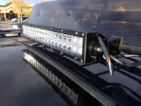
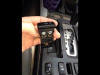
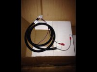
Ok so Darkie3495 you were the catalist in this purchace and I am stoked to get it up and running with my light bar (thanks gaterose GB). But being an eletronics noob/simpleton I need to know how to make these play nice together.
I have very limited know how with wiring up stuff but I am very good at step-by-step directions...:hippie:
Help please...
 

Attachments

  • image.jpg
    image.jpg
    130.9 KB · Views: 1,580
Register to hide this ad
I notice you didn't include a picture of a new relay. Are you not planning to use one or just didn't include it in the photos of the parts you want to work together? Just checking before I try and make a small step by step for you later today should nobody else beat me to it ;)
 
Here's another nice reference from [MENTION=20116]darkie3495[/MENTION] that I used to help in my wiring:
this diagram might help:
Piaa-FJswitch_diagram.jpg~original

And another link I used alot:
Wiring Aftermarket Lights with Toyota FJ Cruiser Off Road Aux Switch - Toyota FJ Cruiser Forum

Here's what I did, it works, others may or may not agree with all of my moves, but I'm confident I won't have any electrical fires, my lights work, the dimmer works right, and I'll be able to troubleshoot the wiring if something fails, which is all that matters to me:

Cut the connector and ring terminal off of the wires on the end that does NOT plug into the FJ switch. These wires need to be wired to other things. You can cut them at the connector, or up closer to the FJ connector, whichever you prefer to your liking for cleanliness. (I like lots of extra wire in case I screw up, or need it in the future, so I cut in about the middle of the harness)

Take that red wire w/ blueish purple tracer (line) on the new harness (pin 1) and run it to one of the coil prongs for the relay you should be installing (typically labeled 86). Now take the red wire w/ green tracer (pin 4), and tap it into that same wire using one of these:
5601.gif~original


Now take the black wire (pins 2) and tap it into the ground on the DAC switch, which is a white and black wire.

Now take the brown or grey wire (the one next to the purple wire, pin 5) on the new harness, and tap that into the white wire the green tracer on the DAC switch. Notice, there are TWO OF THESE. I tapped into the one that was next to the green wire on the DAC switch, NOT the one right next to the white/black one you just tapped into above.

Now take the green wire with a redish purple tracer (pin 3) from the new harness, and send that to one of these:
190257d1261094229-rocker-switch-wont-turn-1c4adfe6-eff3-4dd3-9dc6~original

or these
~original

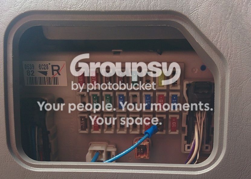
that you should be using on the 'lower right section 7.5A fuse' as mentioned in the above wiring diagram from [MENTION=20116]darkie3495[/MENTION].
lightswitch%20fuse.jpg~original


Now take the last wire, should be the purple one (pin 6) and tap it into the green wire on the DAC switch. (this green wire should be right next to the white/green wire you tapped into previously).

This takes care of the FJ aux switch. You should be able to turn the key to ACC now and test that the switch lights up and dims the same as everything else in the car, and the little light should come on when you press it.

Now we go for the relay.
here's a diagram that may help, mind you the colors, amp ratings, etc. mean nothing, it's just for your reference of wires and where they are going:
relay-diagram.gif~original


You should have one wire on it already, it should be on one side of the coil, typically labeled 86. Now wire a ground to the other side of that coil, usually prong 85 (note that these prongs are not always exactly opposite each other. go by the numbers).

Now you're relay should click when you push the new FJ button (assuming the car is on). All that's left is the light.

Wire 12 volt source (Such as your + side of new fuse block, or + terminal on battery) to terminal 30 or 87 on the relay. Then wire the other terminal (87 or 30) to the + connector on your light. MAKE SURE YOU HAVE A PROPERLY SIZED FUSE BETWEEN THE + SOURCE AND THE LIGHT (whether it's between the source and the relay, or the relay and the light, just make sure its SOMEWHERE on that line). You can use one of these to get a fuse in there if you don't have a fuse block:
15cm-Small-font-b-Fuse-b-font-font-b-Holder-b-font-Blade-Waterproof-font-b.jpg~original


Then run the (-) connector on your light to ground. This can be the (-) terminal on the battery or typically a metal bolt/nut on the body.

Note: your relay may have 5 pins, in which case the 5th one should be left open and is probably labeled 87a.
2nd Note: I wired just slightly different from that reference I have above from darkie. Instead of wiring both pins 2 and 5 to ground, I wired 2 to ground and 5 to the DAC green/white wire. When I did both to ground I had no dimming capabilities on the button. That green/white wire on the DAC button (the one next to the green wire on the button) goes through a dimmer then to ground, and that's how I got my FJ buttons to dim properly.
3rd Note: Use proper wiring sizes.

I realize this is long, probably vague, and I haven't really revised it. Just tried to get something out fast to help you. If you have any questions, PM me and I can do what I can to sort you out.

Good luck!

 
Last edited:
I notice you didn't include a picture of a new relay. Are you not planning to use one or just didn't include it in the photos of the parts you want to work together? Just checking before I try and make a small step by step for you later today should nobody else beat me to it ;)

I have not picked up a relay but do want to use one.
40W
 
Just had a chance to read this through, Fantastic thank you JustinB.
Just what I needed to walk me through it.
I didn't think of looking this up on the FJ forum, i thought since the switch and wiring harness was made for the FJ that it would just be plug and play for them.

Thought I was going to be able to get to this project this weekend but something came up and had meeting all day out of town. Wont know if I need further help until I get into it. But thank you again JustinB for getting on this so quickly. If I did get to do this today as I planned I would have needed it ASAP.
Still now I can get the relay and etc together and I am hoping for tomorrow.

Do I need to look for something specific in a relay?
Also do you recommend 14g wire or should I go for 10g
 
Glad I could help. I'm sure others on here may have other suggestions as well. The best you can do is continue to read up and see what works for you.

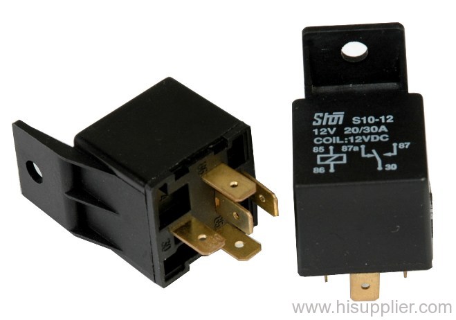
As to the relay, I went with whatever generic relay was available at my local oreilly's, looked like this:
k-shoi$183403401(s).jpg


For the wiring, that would have to be based on the power consumption of that light bar. I put 2 100W lights on top and went with 12 gauge, I also ran a lot of wire as I went all the way to the back of the car, up, and then all the way back to the front. 14 may be fine for your application. Again, it depends on how many actual watts that bar consumes. I'm guessing 10 may be overkill. You can find wire sizing tables online.

Note that this sizing is just for the power wiring from the battery (or fuse block) to the relay and out to the light and back. For the relay coil, and all of the wires from the FJ switch you can go with something smaller like 14 or 16 (I think you could go 18, but I hate dealing with tiny wire).

By the way, I assumed you would figure this out but just to clarify, you're going to need plenty of extra wire to splice from that FJ harness out to the 7.5A fuse, the relay, etc. (the FJ harness just isn't long enough to reach the front of the car ;) )

Good luck on this project, you'll love it once it's done!

PS: I see two FJ switches in your photo, what's the other for? :naughty:
 
Last edited:
Great thanks! I am going to get relay and wire today. We will see if I can smudge together all this info.
The second switch is for the two 6" black oaks I have on order which will go behind the front grill.
 
2 quick questions:
where did you place/attach your relay and where did you ground your relay. Also how did/what did you use to tap into the DAC wires.
Otherwise this has been so clear and well described, exactly what I needed. Thank you again!
 
Last edited:
I placed my relay on the DS fender...I used the factory screw and the relay mounts right there by the fuse box...to tap into the DAC power, I just used a wire tap...super easy and once you're in there...use the wiring diagram and you're set...
 
Sounds like [MENTION=91425]LOSTR4[/MENTION] pretty much answered your questions. I mounted my relay in about the same area as well. As for grounding it, any metal inside there should work, a nearby metal fender bolt or nut should work. Maybe sand away some of the paint on the fender where said bolt/nut makes contact to ensure a good ground.

x2 on the wire tap for the DAC connections. One of those first pictures I stole from the interwebs up in my "step-by-step" (if you wanna call it that) is a blue wire tap, that's what I used.

Let us know how it goes!
 
Well I got the FJ switch wired up and the coil of the relay to the point of testing it with the ACC on the see if the back illumination and "on" light worked. Turned the key and lights on and nada. Bummer.
It was then that I realized that the DAC back illumination is not working and hasn't for so long it didn't occur to me. The DAC function works because when I push the DAC switch on the dash light that indicates it's been activated goes on. Just no back illumination.
Perhaps I could tap into one of the seatheater switches the same way as with the DAC switch. Thoughts about that?

As far as the relay I hooked up to the coil but no "click" with acc test. Agh!
I may have not wired it up correctly. I got a water tight/ pigtail type relay and the only prong that is numbered is the 87.
Will attach a pic.
 

Attachments

  • image.jpg
    image.jpg
    125.1 KB · Views: 1,077
Another.
I'm not sure I am interpreting the diagram right with the wire color coding. The white wire are a smaller gauge of wire so I assumed the were the coil wires. I wired the white to my fj switch harness and black to coil ground. For the larger gauge wires the 87 is labeled and is the blue wire and was going to use the red as the other one. Correct?

Any thoughts?
 

Attachments

  • image.jpg
    image.jpg
    135.2 KB · Views: 1,335
To the DAC lighting: My DAC backlight bulb has been burnt out since I bought the truck, though if you're not getting anything on the FJ switch then something else could certainly be wrong if you are confident in your wiring. I believe others have used the seat heater switches, I don't have any so I can't say. If you have pictures of the wiring between the FJ harness and DAC harness we may be able to help, electrical can be tricky without pictures.

I see 5 wires on your relay. Which colors did you wire to what? I would guess that in relation to my above pin numbering that the following is your best bet:
30 (power from battery/fuseblock/fuse): Yellow
85 (coil neutral/ground): White
86 (coil power from FJ switch pin#4, red w/ green tracer): Black
87 (power to lights, or to fuse then lights): Blue
87a (not used): Red
 
Another.
I'm not sure I am interpreting the diagram right with the wire color coding. The white wire are a smaller gauge of wire so I assumed the were the coil wires. I wired the white to my fj switch harness and black to coil ground. For the larger gauge wires the 87 is labeled and is the blue wire and was going to use the red as the other one. Correct?

Any thoughts?

This wiring should have worked as far as the relay coil is concerned (typically the coil +/- wiring doesn't matter as long as one is + and one is -). But using that red wire I would guess your lights would be on all the time (using the normally closed contact). I would look at my above post and I would also guess you are missing something on the FJ switch and DAC harness connections.

You just reminded me, if you wire that appropriately and it works, you should cap the unused wire as it will have 12VDC hot on it anytime the light bar isn't on. Not a huge deal, just could lead to a blown fuse now and again if it touches metal. (This reminded me I should probably go cap an extra prong I have on one of my relays :) )
 
Last edited:
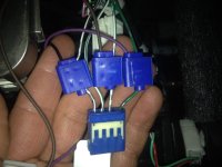
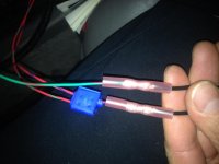
Here are 2 pics of the wiring. Hope it is clear enough.
And duly noted I will cap the 5th tab
 

Attachments

  • image.jpg
    image.jpg
    128.8 KB · Views: 227
The set on left with 2 red wires goes to relay and right to pigtail in dash fuse box 7.5 bottom slot second in from left
 

Attachments

  • image.jpg
    image.jpg
    129.9 KB · Views: 220
Well done, that looks like a pretty clean job. Clean enough to have me befuddled for now. Assuming that green wire red tracer goes to an ACC 12v power source, and those two red wires with green and purple tracers go to the relay you, then I'd have to question my directions and wonder if I confused the relay coil wiring. I'll take a look in the morning and let you know. If you have access to a multimeter I would suggest checking continuity between the pins of the DAC and FJ switches to ensure your wiring connections are good.
 

Members online

Forum statistics

Threads
278,310
Messages
3,554,080
Members
248,016
Latest member
Advally Service

Trending content

Back
Top