High Beam Indicator - What Triggers it?

DaMonkey

New member
Stock:

Each headlight harness (9003) has 3 wires: hot wire that goes hot for both hi/lo, a ground wire that switches for lo beam, a ground wire that switches for hi beam. When no lights are on, each wire in the 9003 floats (neither hot or grounded).


Now modified:

Each 9003 harness now drives a bosch style automotive relay.

On both sides of truck, the hot wire from the 9003 harness now goes to 85 on a relay which is the hot side of the trigger solenoid to turn on bulb. The ground side of the trigger solenoid goes to a constant ground, so the lo beam grounding switch wire from 9003 harness is now empty.

On both sides of truck, the hot wire from the 9003 harness also drives the hot side of another solenoid that triggers the high beam shutter. The ground side of that solenoid goes to the high beam grounding switch in the 9003 harness.

Situation:

This setup is great. It works perfect because with this setup, there is no power interruption to the HID ballast just to trigger the hi beam shutter. If I wired the lo beam solenoid ground to the 9003 harness, there would be an interrepution to the ballast. The interruption is why people need to install a capacitor to carry that brief power during the hi/lo switch on a retrofit.

I would have just bought a harness like the Morimoto one, except I really don't like it because it only pulls from one side of a dual circuit to go through one fuse and one relay to then split again and drive both left and right. That's super dangerous. Any failure point through that harness will knock out both lights at once. No thank you.

I made my harness with redundant circuits for both sides and they have independent fuses and relays. It works great, but the dang blue light on my dash does not work anymore. Not that I really need it... I sure know when high beams are on lol.

When switched for lo beams, there is very little solenoid current through the hot 9003 that grounds common (so there is no current returning back through the lo switched ground in 9003).

When switched for high beams, there is very little solenoid current through the hot 9003 that grounds back through the hi switched ground. And there is still a little more hot current that's still driving the lo beam solenoid.

So I can't imagine why the hi beam indicator stopped working?
 
Register to hide this ad
Stock:

When switched for lo beams, there is very little solenoid current through the hot 9003 that grounds common (so there is no current returning back through the lo switched ground in 9003).

When switched for high beams, there is very little solenoid current through the hot 9003 that grounds back through the hi switched ground. And there is still a little more hot current that's still driving the lo beam solenoid.

So I can't imagine why the hi beam indicator stopped working?

I haven't checked the wiring diagram yet, but I believe the indicator light on the dash is powered in series with the high beam circuit.

I just lost my hi beam indicator too, because of new LED I just put in. The high resistance of the LEDs doesn't allow enough current to light the indicator.

A couple ways to fix:

1. Isolate the indicator light circuit and re-wire it to run in parallel with the hi beam circuit - it sounds like this should work well for your setup. This would probably not work with the stock wiring, because it would back feed voltage to the low beams as well.

2. Add a load resistor in parallel with the hi beam circuit to allow more current to light the indicator - I might do this, because it's quick and easy.
 
*for the non-DRL trucks*

The high beam indicator is powered through the low beam filaments of the headlight.

When the low beams are on, the high beam indicator is shorted to ground. When the high beams are on, the 'low' side of the low beam filaments are floating (go up to 12V+) and then can power the high beam indicator. When light bulb filaments are 'off' they are very low resistance, so the 45W filaments (x2) can easily power a 1.5W (or whatever) bulb for the indcator.

It is up to you whether you want to figure out a reasonable way to wire around this... It might be a fairly low value resistor in place of a low beam filament (like, <100ohm of appropriate wattage) or a new wire up to the dash to power the bulb from the high beam shutter power...

-Charlie
 
I haven't checked the wiring diagram yet, but I believe the indicator light on the dash is powered in series with the high beam circuit.

I just lost my hi beam indicator too, because of new LED I just put in. The high resistance of the LEDs doesn't allow enough current to light the indicator.

A couple ways to fix:

1. Isolate the indicator light circuit and re-wire it to run in parallel with the hi beam circuit - it sounds like this should work well for your setup. This would probably not work with the stock wiring, because it would back feed voltage to the low beams as well.

2. Add a load resistor in parallel with the hi beam circuit to allow more current to light the indicator - I might do this, because it's quick and easy.

Thx ! :hatsoff:

#2 makes sense. I just jumped some small wattage resistors I had in my box. Added to both sides in the hi beam circuit to add about 0.7 watts burning each side when high beams are on. Didn't do it. I'll plop more in when i get a chance to flow more current and see when it triggers. Any way to tell from wiring diagram (or intuition) how much load it would need?

Hopefully we don't need to really juice it up just for the indicator.
 
I haven't checked the wiring diagram yet, but I believe the indicator light on the dash is powered in series with the high beam circuit.

I just lost my hi beam indicator too, because of new LED I just put in. The high resistance of the LEDs doesn't allow enough current to light the indicator.

A couple ways to fix:

1. Isolate the indicator light circuit and re-wire it to run in parallel with the hi beam circuit - it sounds like this should work well for your setup. This would probably not work with the stock wiring, because it would back feed voltage to the low beams as well.

2. Add a load resistor in parallel with the hi beam circuit to allow more current to light the indicator - I might do this, because it's quick and easy.

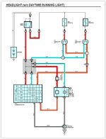
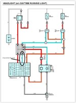
Well, you ought to check the wiring diagram, because everything you posted is wrong. It is not truly a high beam indicator, it is a "lows not on" indicator, at least on your '96 which will not have DRLs unless it is Canadian. . It is wired between the ground side of the low filaments and chassis ground. When the ground switched low filaments are on, no current flows through the indicator because it all goes directly to ground. When highs are on, current flows through the cold low filaments to the indicator to ground because the direct ground is switched off.

I suspect the issue with your LEDs is that it does not flow any current through the low side when the highs are on. I'd need a good understanding of how your LEDs are switched to give a solution to this.

I'll help the OP, too, but he has to post year and whether he has DRLs or I can't help him.

EWD for '96:
 

Attachments

Last edited:
You don't have OEM DRLs right? Try this if you still have the wiring loose. Bypass your custom harness for now.

1) Connect one high beam solenoid wire to the common bulb positive

2) Connect the remaining high beam solenoid wire to the high beam negative

3) Turn high beams or flash on. Solenoids should activate. Did the highbeam indicator work?
 
Thanks Durk.

I was mistaken. The indicator is in series with the low beam circuit.

For stock wiring, a parallel load resistor on the low beam side would allow enough current to pass in order to light the indicator.
 

Attachments

  • Headlight.jpg
    Headlight.jpg
    59.1 KB · Views: 8,066
98 non-DRL.

I can draw it if that helps.

Thx for any input.

Here's my arrangement that is functional, but no indicator.

4hebfk.png
You don't have OEM DRLs right? Try this if you still have the wiring loose. Bypass your custom harness for now.

1) Connect one high beam solenoid wire to the common bulb positive

2) Connect the remaining high beam solenoid wire to the high beam negative

3) Turn high beams or flash on. Solenoids should activate. Did the highbeam indicator work?

No DRL. 98.

My arrangement effectively does that. I just pulled the bulb relays out and tried what you suggested. Of course the bulb did not go on, but the shutters activated for hi beam. No indicator light though.
 
Thx ! :hatsoff:

#2 makes sense. I just jumped some small wattage resistors I had in my box. Added to both sides in the hi beam circuit to add about 0.7 watts burning each side when high beams are on. Didn't do it. I'll plop more in when i get a chance to flow more current and see when it triggers. Any way to tell from wiring diagram (or intuition) how much load it would need?

Hopefully we don't need to really juice it up just for the indicator.

It sounds like you don't need to add any resistors. Instead try powering the low beam side ground of the 9003 harness with your high beam relay. (tie the low ground trigger and high ground trigger together on the 9003 harness)

That will power the indicator light when you switch to hi beams
 
Last edited:
It sounds like you don't need to add any resistors. Instead try powering the low beam side ground of the 9003 harness with your high beam relay. (tie the low ground trigger and high ground trigger together on the 9003 harness)

That will power the indicator light when you switch to hi beams

My high beams would always be on if I tied those two together?
 
My high beams would always be on if I tied those two together?

Darn. Yep

Might have to add another relay (only needed on one side) to power the low beam ground wire when the hi beams are turned on. Or the load resistor from Hi/Lo +12V to the low beam ground.
 
Last edited:
I already gave you the right answer... please read my post.

Two options:
1. Add low-value resistor in place of original low-beam (I have used two 100ohm 5-watt reisistors in parallel successfully in the past).
2. Add a wire from the high beam shield power to the gauge cluster (cut original wire, connect to Blue-Black wire on gauge cluster).

Adding the load/bypass resistors is much easier and easily reversible...

-Charlie
 
I already gave you the right answer... please read my post.

Two options:
1. Add low-value resistor in place of original low-beam (I have used two 100ohm 5-watt reisistors in parallel successfully in the past).
2. Add a wire from the high beam shield power to the gauge cluster (cut original wire, connect to Blue-Black wire on gauge cluster).

Adding the load/bypass resistors is much easier and easily reversible...

-Charlie

Sorry Charlie (had to do it :)

I was not able to make sense out of the diagram, but I get the gist of what's happening. 100 ohms each side? or 100 ohms in parallel each side? or parallel one side?

To confirm, this goes from my empty lo-ground switch in the 9003 harness to the +12 in the harness?

30vlvro.png
 
Phatty's idea should work, although I'd wire the resistor(s) to the high ground and common positive.
 
I'd go the indicator to resistor to switched high beam 12V+ approach. The value of the resistor should be the same as two cold low beam stock filaments in parallel. Measure one bulb and use this formula for two, where R1 and R2 are the value of the single cold low filament resistance.


1/Rt = 1/R1 + 1/R2

Don't calculate backwards from bulb wattage as cold and hot filament resistance are very different. Resistor wattage does not need to be very high as the indicator will not pass that much current. You don't need one of those big ass coil load resistors.

If somebody measures the voltage to ground on a stock setup at a point between the indicator and the low filament with highs on we can calculate the current draw through the resistor/indicator and thus the resistor wattage needed (once we have measured the filament resistance.)
 
Last edited:
Sorry Charlie (had to do it :)

I was not able to make sense out of the diagram, but I get the gist of what's happening. 100 ohms each side? or 100 ohms in parallel each side? or parallel one side?

To confirm, this goes from my empty lo-ground switch in the 9003 harness to the +12 in the harness?

30vlvro.png
Two 100 ohm resistors total. You could put one on each side or two on one side - your choice. Where you drew the connection is correct. They will be dissipating around 4 watts (total) so I suggested 5W parts to be safe. It should allow enough current to pass through the high beam indicator to light it sufficiently.

Something like this should work: https://www.digikey.com/product-detail/en/stackpole-electronics-inc/CB5JB100R/CB5JB100R-ND/1740793

Phatty's idea should work, although I'd wire the resistor(s) to the high ground and common positive.
The high beam indicator has nothing to do with the high beam filaments. If you want the high beam indicator to turn on, you need current to flow through the low beam filament, or where it used to be. Take a look at the diagram TheDurk posted.


If somebody measures the voltage to ground on a stock setup at a point between the indicator and the low filament with highs on we can calculate the current draw through the resistor/indicator and thus the resistor wattage needed (once we have measured the filament resistance.)
A cold bulb filament will measure near 0 ohms. The current to light a small #74 bulb isn't enough to heat the filament, so it will still be very low resistance and essentially a short. The 50 ohm total load I chose here is a compromise to get enough brightness out of the high beam indicator while not creating big heat source where it shouldn't be needed.

-Charlie
 
Here's another idea:

If you can find the light control switch and disconnect the light blue #17 wire, that would remove the extra path to ground (which you are not using for the low beams). Likewise you could disconnect that side of the ground wire at the J4 junction plug - interruption at any point along that ground path will do.

Then you can run power to the low beam wire on the 9003 plug directly from the high beam circuit.

No resistors, or extra relays needed...
 

Attachments

  • HL Switch.JPG
    HL Switch.JPG
    120.9 KB · Views: 824
Last edited:
Here's another idea:

If you can find the light control switch and disconnect the light blue #17 wire, that would remove the extra path to ground (which you are not using for the low beams). Likewise you could disconnect that side of the ground wire at the J4 junction plug - interruption at any point along that ground path will do.

Then you can run power to the low beam wire on the 9003 plug directly from the high beam circuit.

No resistors, or extra relays needed...

But what reduces the voltage to the indicator? No filament, no resistor...
 
But what reduces the voltage to the indicator? No filament, no resistor...

Nothing. It’s not needed if the extra ground path is taken away. A load resistor is only needed to flow extra current when a single resistive load is too big ( or absent in this case).

Voltage is always equal across all loads in a parallel circuit regardless.
 

Members online

Forum statistics

Threads
278,310
Messages
3,554,080
Members
248,016
Latest member
Advally Service

Trending content

Back
Top