HowTo: rear backup camera mod

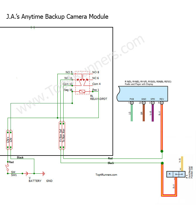
The dual throw relay isolates the signal so that it does not back feed into the ecu which may cause some issues.

Here is the Backup Camera Only portion of the mod I have done which can be seen in detail at Toyota 4Runner Video on Nav and Anytime Backup Camera Mods, hope it helps.

backupcamera_schematic.jpg

I know this should be a suimple project to just add a switch to have the nav screen display the rear view camera, but I have tried several times. I can get the switck to work but after a few times the camera will switch on the reverse lights, then I get a dash light showing the vsc is light up. I can clear the vsc light and turn off the back up lights with a code reader. I would like to be able to use this mod since I tow a jeep trailer off road. Can you offer some help with this? you seem to be very good at this. I also noticed that you have made a devive to take care of this. I just need a simple switch mod.

Thanks for all your help on past mods.

dwinev33
 
I tried just a switch, I am not sure how to wire the relay. I could use a diagram of just the relay and switch wireing. Aslo what relay model number did you use? I know that this works and it should not be this complicated. I have done other wireing mods but not with relays. Thanks for the rast reply and past help on 4 runner projects

dwinev
 
I tried just a switch, I am not sure how to wire the relay. I could use a diagram of just the relay and switch wireing. Aslo what relay model number did you use? I know that this works and it should not be this complicated. I have done other wireing mods but not with relays. Thanks for the rast reply and past help on 4 runner projects

dwinev

The diagram is above and the part number on my site.
 
The diagram is above and the part number on my site.

No offense J.A. but your understanding far exceeds some of us so what is obvious to you is foreign to us. I'm also interested in doing this but need a more simplistic diagram.
 
No offense J.A. but your understanding far exceeds some of us so what is obvious to you is foreign to us. I'm also interested in doing this but need a more simplistic diagram.

Understand, but the diagram posted says it all. Need more pointed questions to be of assistance. The relay is a Panasonic DS2E-S-DC12V DPDT 12V PCB Mount Relay. Solder it to a board and connect the wires as shown. Happy to help but not sure how to. Let me know.
 
CXS is righr, but it's becimming mor clear after going back to your diagrams and instructions. I have ordered the relay after re-reading your instructions and diagram. It was not that easy for us that don't know how th read electric diagrams and we all don't know the electric symbals. I think I have it now. I'll let you know if I was successfull.

thanks for helping with this...this is one mod I have been trying for some time..

dwinev
 
Thanks for the offer J.A. I'm going off the 1st post in this thread rather than yours due to my inability to follow yours. You replied that a relay was needed but I'm unsure of where this needs to be added. I also think you and the OP used different switches, is a DPDT what you recommend? Ideally a simple drawing showing the placement of the relay would be great.
 
Let's go back to basics and start with a normal automotive 12V single pole dual throw relay available at any automotive parts store. This requires NO soldering but rather uses the more commonly available crimp type connectors.

relaytextA2.gif


The relay can be in either the unenergized or energized states. Let's start with unenergized as seen here.

relaytext2b.gif


To start wiring this for the backup camera mod. Find the red with yellow stripe reverse camera wire behind the nav screen.

Cut it clear thru...in half. Wire the cut side coming from the vehicle to pin 87a on the relay and the cut side to the nav screen to pin 30. By doing this you basically put the cut wire back together and your vehicle will function as normal.

But when the relay is energized (which occurs when the coil on the relay is energized) the red with yellow stripe wire is "opened" (disconnected). See figure 3.

relaytext3b.gif


To energize the coil you need to have positive and negative at pins 85 and 86. So simply run a ground to pin 86 first. Then wire a single pole single throw switch so that 12V positive goes to one side of the switch and the other side goes to pin 85 on the relay. When you turn the switch on the relay is energized and the reverse wire is "broken".

With the switch on and the reverse sensor wire is broken, we can send a 12V positive signal thru the relay (via pin #87) and out to the camera via pin 30 with out backfeeding it to the vehicle which is at pin 87a.

How do you get 12V+ to 87? Simple, just send a wire from the switch output to 87 as well as 85 at the same time.

The nav screen sees 12V positive coming in and turns on even while moving forward, but since the 12V positive is not feeding thru out the circuit to the vehicle no adverse effect are realized.

Hope that helps, any questions let me know.
 
Thank you, that is exactly what I need and can understand. One final question; you cut the wires behind the nav screen while the OP skinned them below the screen - can you explain the different approaches and why yours is better?

Thanks for your simplifying it to my level!
 
I can understand this. This is what I have been looking for, simple, easy to follow and complete. I appreciate your taking time out to make this easier for us amatuers.

dwinev
 
Thank you, that is exactly what I need and can understand. One final question; you cut the wires behind the nav screen while the OP skinned them below the screen - can you explain the different approaches and why yours is better?

Thanks for your simplifying it to my level!

If you just skin/strip the wire without cutting it thru, any power put to the nav screen will back feed into the circuit. By cutting it and wiring it into a relay, the relay connects it and disconnects the wire halfs as per the direction of the switch. Switch off, the cut wire is connected. Switch on, wire disconnected (avoiding backfeeding the circuit) and allows 12V+ to be piped directly into the nav screen tricking it to turn on the backup camera.
 
Perfect description, I get it now and see the difference between using and not using a relay. The feedback is what i was missing. Now that I understand I'll do it as soon as I get a chance. Thank you very much J.A.!
 
JA
Tried your last post using the 12 volt auto relay. Did as instructed. Turned on the nav screen with the SPST turned off in reverse the camera was on, with the switch powered on the the rear view camera was off. Then when I turned on the switch to activate the camera in drive nothing. Guess somehow I am not powering the camera. I think I did okay until the point of powering up the camera when in drive.....could use some help clearing up wireing post 87 with 30


dwinev
 
Good to see you,re ahead of me on this dwinev! Looking forward to you working out the details.
 
JA
Tried your last post using the 12 volt auto relay. Did as instructed. Turned on the nav screen with the SPST turned off in reverse the camera was on, with the switch powered on the the rear view camera was off. Then when I turned on the switch to activate the camera in drive nothing. Guess somehow I am not powering the camera. I think I did okay until the point of powering up the camera when in drive.....could use some help clearing up wireing post 87 with 30


dwinev

Did you bring 12V+ to both 87 and 85 via the SPST switch?
 
I will try this tomorrow, I went form the 12 volt + to the relay post 85, that is where I went wrong, I'll try to wire 12+ to the switch first then to 85 and 87 via the switch. Does the negative to 86 also come from the switch?

thanks for the help

dwinev
 
I will try this tomorrow, I went form the 12 volt + to the relay post 85, that is where I went wrong, I'll try to wire 12+ to the switch first then to 85 and 87 via the switch. Does the negative to 86 also come from the switch?

thanks for the help

dwinev

Your switch will only have negative if it has a light on it. You can get the negative over to 86 from any ground point.
 

Members online

Forum statistics

Threads
278,310
Messages
3,554,080
Members
248,016
Latest member
Advally Service

Trending content

Back
Top