Isolating Fog Light portion of Left Column Stalk

drdolittlerwc

New member
I've read the threads involving a 'Fog Light Mod', and they all (or at least the ones I've read) talk about bypassing the DRL's & High's to operate Fog's when desired.

This is not what I'm trying to accomplish, but of course, I'm new to these sort of mods and so I don't even know if what I am about to ask is possible. So, if it is not, I'm sure there is someone smart enough out there to tell me. Don't worry, I can take it!:croc:

I would like to completely eliminate the fog light circuit, but keep the switch, which I would then use to switch an aftermarket light bar. I have the complete wire harness w/ switch, but would rather use the stock switch.

I don't have fogs anymore since I've changed out my bumper.

Basically, I need to know if the switch on the stalk has enough dedicated wire connections to 'exchange' the routing/wire connections. From what I've read this switch seems to be tied into the DRL circuit, hence the mods...

Any help would get me out of this psych spiral.... :ybrick:
 
Register to hide this ad
Looking forward to the answer to this. I've got my fogs wired up to a relay under the dash and would love to use the stock fog light switch.
 
Why eliminate the existing circuit? At least keep the relay, unless your light bar requires the Hoover Dam to power up. Even then, I would think it would be easier to daisy chain two relays: the existing fog relay and a new larger one for the bar. But the switch goes between T10 and T11 on the stalk switch. You can isolate it if you choose to. I'm pretty sure there is only one part number for a stalk with fogs, so the T10/T11 thing should apply to all years. Wire colors may vary. On a 2002, they are green-black(T10) and black-red(T11). The pin-outs are shown at C13 here:

http://tacoma.site40.net/4Runner_96-02_Repair&Wiring/techinfo.toyota.com/ileaf/ewdtmc2/ewdtmpdf/ewdsourc/2002/024runne/connecto/connecto.pdf

People do the mod because the factory fog circuit only comes on with the low-beams. The way I see to defeat that is intercept the green-black wire from T10 of the stalk switch and run it straight to a full-time ground. Then you can use the rest of the circuit as you see fit within its power limitations.(This is on a 2002--the only schematic available to me. I can't be sure if it would be the same on your year.) I haven't done this, I'm just looking at the schematics.

http://tacoma.site40.net/4Runner_96-02_Repair&Wiring/techinfo.toyota.com/ileaf/ewdtmc2/ewdtmpdf/ewdsourc/2002/024runne/systemci/021ffl.pdf

http://tacoma.site40.net/4Runner_96-02_Repair&Wiring/techinfo.toyota.com/ileaf/ewdtmc2/ewdtmpdf/ewdsourc/2002/024runne/systemci/020hldrl.pdf
 
Last edited:
Why eliminate the existing circuit? At least keep the relay, unless your light bar requires the Hoover Dam to power up. Even then, I would think it would be easier to daisy chain two relays: the existing fog relay and a new larger one for the bar. But the switch goes between T10 and T11 on the stalk switch. You can isolate it if you choose to. I'm pretty sure there is only one part number for a stalk with fogs, so the T10/T11 thing should apply to all years. Wire colors may vary. On a 2002, they are green-black(T10) and black-red(T11). The pin-outs are shown at C13 here:

Now THAT is the tip of the day!! :guitar3: THANKS!!

I understand the reason for the existing circuit mod, but I no longer have stock fogs, and my light bar is 120w (too much for one feeder from the fog circuit, and trying to mod the existing circuit seemed kinda cumbersome and I'll say it... hokie).

As you can see here, the company I bought the light from supplied me with the complete harness (circuit) for the light bar (waterproof connector, relay, fuse, switch etc. + a heavier gauge wire to feed the bar), but I would like to be able to 'cut & paste' the wiring to the fog switch. Hence the need to isolate.

drdolittlerwc-albums-light+bar-fog+switch+mod-picture21434-img-0206.jpg


I was looking at my stalk connector and it looks like the wires you suggested are correct (both color and placement). I just want to confirm that these are the wires I need. Also, the switch I have shows HOT (+), RELAY, GROUND. Since there are three wires on the provided switch, will I need to isolate 3 wires or can I just connect 2, and if so, which ones???:confused:

drdolittlerwc-albums-light+bar-fog+switch+mod-picture21369-bottom-view-wires-entering-connector.jpg
 
OK, I think I might be starting to think this through a little better....

I remember while poking around with a tester and flipping switches, that the Yellow wire is the + for the stalk. Correct??

Which would leave me with Black/Red (Relay??), and Green/Black (Ground?)

Now, can I use the + to the stalk for the Relay trigger?

Please remember, I'm new to the whole relay issue. I can wire a whole house, but these nuances escape me...:roadkill:
 
Here's what I did. http://www.toyota-4runner.org/3rd-gen-t4rs/115227-mod-use-fog-light-switch-driving-lights.html Sounds exactly like what you want to do. It was quick and easy, with minimal changes, and easily reversable.

Thanks!

One of the big differences I'm want to achieve is to increase the feeder wire size to the light bar. As you know, the fog lights are 55w each (with 2 separate feeders) and my bar is 120w (with a single feeder). So, if I use the original circuit, even with a simple mod, I will also have to deal with the smaller gauge wire issue that will cause either a voltage drop (lowering my light output) or even worse..... let's not talk about that.........
 
I would tap the RELAY wire to Terminal 2 of the FOG relay (described as an alternative in the link posted by [MENTION=59733]98OzarksRunner[/MENTION]). The FOG relay needs to stay in place when you do this. RELAY then goes to the coil side of the new relay in your light bar harness. The GROUND wire can be taped off--I presume this only needed for an indicator light in the new switch which you will not be using. The HOT wire can also just be taped off. Leave the stalk switch alone. This is what I meant when I said: "daisy chain two relays: the existing fog relay and a new larger one for the bar." I prefer this because you don't have to mess with the stalk wiring nor the new harness.

Or you could do as posted in the link. You are only running relay coil current through the stalk switch so power is not a concern with either approach. Your new harness will source its own power for the lights. So then: Cut and ground the green-black wire from the stalk, either at the stalk or at the relay as he describes. Connect the RELAY wire to Terminal 2 of the old FOG relay as he describes. Then you have to connect the other side of the relay coil in your new harness to a 12V+ because the stalk is switching ground and I am pretty sure your new relay coil has ground on the other side. The other wires to the new switch can just be taped off.

If you could post the schematic of the new harness I could be more certain about this. The important thing we need to know is whether the other side of the new relay coil is wired to ground or 12V+. They could do it either way since both are present at the new switch in the harness because both are needed for the indicator light and I don't know which the switch is switching, so to speak. I have assumed on all the above that the new switch is set up to switch hot, but I can't be sure. This is critical to know for sure. Usually they switch hot because then they tell you to tap hot from a key-on source. It's very hard to find a key-on ground.
 
Last edited:
Thanks!

One of the big differences I'm want to achieve is to increase the feeder wire size to the light bar. As you know, the fog lights are 55w each (with 2 separate feeders) and my bar is 120w (with a single feeder). So, if I use the original circuit, even with a simple mod, I will also have to deal with the smaller gauge wire issue that will cause either a voltage drop (lowering my light output) or even worse..... let's not talk about that.........

I'm not sure what you're saying (sorry), but it sounds like you are concerned about the current for the lights running through the original fog light circuit. In my mod, the power for the lights comes directly from the battery through its own fuse (in my case, a 15 amp since that's what came with the lights) and is switched by the contacts on the added relay (Relay 1 in my diagram is not the original fog light relay but is the new relay. Its coil wires connect to the under-hood fuse panel where the original fog light relay plugged in). The wire could be 0 gauge with a 100 amp fuse if you want, since the power side (battery to lights) is totally isolated from the original fog light wiring (but you'll need a big relay or contactor for that much current :) ). The original wiring just powers the coil for the relay. It accomplishes what you want with no added wiring inside the cab - it's all under the hood, and no cutting and splicing wires for the fog light switch. The only wiring change is to ground the green/black wire on the DLR controller, and plug the new relay coil wires into the fuse panel where the old fog light relay was. Easy as pie. The whole mod took less than an hour, and most of that was figuring out the factory wiring.

If you want to understand what the mod does - it's 2 things. First, it overrides the high-beam shutoff for the fog lights. Grounding the green/black wire does that. Second, it REPLACES the original fog light relay with a new one and the original fog light circuit simply powers the coil on the new relay. You add your power circuit for the light bar to the contacts on the new relay, and since it's isolated from the original circuit by the new relay, it can handle as much current as the relay contacts and your new wiring can handle.

I modified the original schematic to clarify the connections.

Driving%20Lights%20Wiring.jpg
 
Last edited:
If you want to understand what the mod does - it's 2 things. First, it overrides the high-beam shutoff for the fog lights. Grounding the green/black wire does that. Second, it REPLACES the original fog light relay with a new one and the original fog light circuit simply powers the coil on the new relay. You add your power circuit for the light bar to the contacts on the new relay, and since it's isolated from the original circuit by the new relay, it can handle as much current as the relay contacts and your new wiring can handle.

OK, as I like to say, I think we are on the same page but just reading different paragraphs.

I understand that the fog circuit is controlled by the ground thru the DRL relay, correct?

That ground is also located coming out of the stalk connector, correct?

The relay trigger (switch leg), is the Black/Red wire out of the stalk connector, correct?

So, next question, the larger yellow wire is the hot (+), correct? Is this supply a 'constant' to the whole stalk 100% of the time? If so, can this supply be 'substituted' for the supply to the switch that is included in the new circuit that I received with the light without damaging the circuit/relay?

My goal is basically to introduce a 'new' circuit and use the stock switch to 'trigger' the relay in that new circuit. I'm assuming the 12v DC is a constant and it would not be similar to adding a 'phase' as on a house circuit.

I would disconnect the Green/Black at the stalk connector and create a 'hard ground', and connect my switch ground to the portion. Then clip the Black/red wire from the connector to my relay trigger (switch leg) on my new circuit. Only wire that would be left out is the power supply, which would come from the stalk (if it is constant).

The wire harness (circuit), I have is (from the start), connected directly to the battery/ground, and provides a hot(+) to the switch. My main concern is if there will be a conflict in the circuit if I don't use the provided hot by replacing it with the stalk hot.

Does that clarify it? :suspicious: I'm sure I just created a slew of additional ???????

I've already opened up my steering column so I'm not worried about what it takes to get it done. It's just that my mind sees it being a more complete solution for my needs....
 
1. I don't see a yellow in the schematics at the stalk. Only two red-yellows that may show 12V+ but are really on the ground side of loads, no good for you.

2. A relay triggers when you have ground on one side of its coil and 12V+ on the other. The red-black provides a switched ground you can feed to one side.(the RELAY wire).

3. Then the other wire to the relay coil in the new harness must go to a 12V+. Full-time if you want full-time, key-on if you want that, etc. If you don't modify your new harness, you will have ground on both sides and nothing will work (assuming I am right on how it is wired.)

Or you can make the stalk switch provide a 12V+ signal on red-black by moving green-black to a 12V+ source. There is nothing in the stalk circuit that I can see, yellow or any other color, that would be a useful 12V+ source, as the whole thing is set up to switch grounds.

Focus on how your new relay coil is wired. It can be:

ground >> switch >> coil >> 12V+; or

12V+ >>switch >> coil >> ground. Either will work. What you can't do is have ground on both sides or 12V+ on both sides.
 
1. I don't see a yellow in the schematics at the stalk. Only two red-yellows that may show 12V+ but are really on the ground side of loads, no good for you.

2. A relay triggers when you have ground on one side of its coil and 12V+ on the other. The red-black provides a switched ground you can feed to one side.(the RELAY wire).

3. Then the other wire to the relay coil in the new harness must go to a 12V+. Full-time if you want full-time, key-on if you want that, etc. If you don't modify your new harness, you will have ground on both sides and nothing will work (assuming I am right on how it is wired.)

Or you can make the stalk switch provide a 12V+ signal on red-black by moving green-black to a 12V+ source. There is nothing in the stalk circuit that I can see, yellow or any other color, that would be a useful 12V+ source, as the whole thing is set up to switch grounds.

Focus on how your new relay coil is wired. It can be:

ground >> switch >> coil >> 12V+; or

12V+ >>switch >> coil >> ground. Either will work. What you can't do is have ground on both sides or 12V+ on both sides.

Sorry, I must have posted these pics in another thread.

drdolittlerwc-albums-light+bar-fog+switch+mod-picture21372-top-view-wires-entering-connector.jpg


drdolittlerwc-albums-light+bar-fog+switch+mod-picture21369-bottom-view-wires-entering-connector.jpg


drdolittlerwc-albums-light+bar-fog+switch+mod-picture21370-straight-view-light-stalk-connector.jpg


This is my stalk connector. The Larger Yellow wire is 12v+, I checked it, I just didn't check whether it was Key on or not. I'm assuming that 12v+ is supplied to the whole stalk continuously regardless of switch position since the circuits are controlled by grounds and relays.

I am going to splice the green/black at the connector to ground. Then I will splice the black/red to the new relay. This is according to the connector diagrams and wire call outs given in this thread, and I believe them to be the very same, same I have already ran through them with an ohm meter.

My concern is the 12v+ for the relay trigger ONLY, as the new circuit connects it's own power directly to the battery and a hard ground. My question is, will 12v+ from the stalk conflict with the relay in the new circuit in a negative way? I am assuming not, since they are both 12v+ and no new phase is being introduced.

Notice my circuit and switch below...

drdolittlerwc-albums-light+bar-fog+switch+mod-picture21371-switch-belonging-wire-harness-aftermarket-light-bar.jpg


drdolittlerwc-albums-light+bar-fog+switch+mod-picture21435-img-0207.jpg


Thanks for all your patience and help!

I'm going to do this Sat afternoon, so if you see smoke on the horizon, don't send the cavalry, just send prayers....:violin:
 
Notice my circuit and switch below...

drdolittlerwc-albums-light+bar-fog+switch+mod-picture21371-switch-belonging-wire-harness-aftermarket-light-bar.jpg

I read briefly through these post so forgive me if I misunderstood you. Can you clarify that at one point you had factory fog lights? And after changing bumpers, there is no longer a bulb at the end of the wiring?

If not, you can stop reading. I missed the details.:doh:

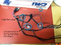
But, if that is the case, you can remove the rocker switch that came with the wiring harness, I'm seeing three wires so I presume there's a LED on the switch, replace the switch with the correct lightbulb connector (H3?).

(See attachment) Now you can connect in the wiring harness to where the fog light bulb would go. Since you're still using a wiring harness, the wiring on the switch side is only powering a solenoid so wire gauge is not an issue. The wires you connect to the battery on the wiring harness are the ones powering the new light, so they are sized correctly from the company.

Hope this helps.
 

Attachments

  • user94182_pic21435_1380594370.jpg
    user94182_pic21435_1380594370.jpg
    81.7 KB · Views: 626
Sorry, I must have posted these pics in another thread.

This is my stalk connector. The Larger Yellow wire is 12v+, I checked it, I just didn't check whether it was Key on or not. I'm assuming that 12v+ is supplied to the whole stalk continuously regardless of switch position since the circuits are controlled by grounds and relays.

I am going to splice the green/black at the connector to ground. Then I will splice the black/red to the new relay. This is according to the connector diagrams and wire call outs given in this thread, and I believe them to be the very same, same I have already ran through them with an ohm meter.

My concern is the 12v+ for the relay trigger ONLY, as the new circuit connects it's own power directly to the battery and a hard ground. My question is, will 12v+ from the stalk conflict with the relay in the new circuit in a negative way? I am assuming not, since they are both 12v+ and no new phase is being introduced.

Notice my circuit and switch below...

Thanks for all your patience and help!

I'm going to do this Sat afternoon, so if you see smoke on the horizon, don't send the cavalry, just send prayers....:violin:

Are you sure that is a yellow and not a yellow-red?--the pictures and the schematics tell me it's yellow-red, but the pics aren't super clear as to the red part. If it is yellow-red, then it is from Pin #2(which it looks to be), and is the supply to the turn signal circuit, which is key-on and south of the flasher.As I read it, that 12V+ will flash like a blinker, which is probably not what you want your light bar to do. I would check that with your meter again, although the load of the meter alone is so small that the flasher may not cycle unless the bulbs are loading the circuit so that is why it LOOKS to be a solid 12V+. I'm not sure what happens if you load the the flasher with the just the relay coil. But I AM sure that your light bar will flash with the turn signals every time you use the blinker because then the flasher will surely cycle. So no, you can't use that as a 12V+ source for your new fog relay unless you never use the blinker and the bar at the same time. (LOL--but no phase issues, boy you really ARE a house wiring guy!--autos are as single-phase as a flashlight. DC=no phases.) Try your meter on that wire with the key on AND the turn signal operating and see what you get.

My concern continues to be how you connect any 12V+ to your new relay. You have to make sure that 12V+ goes to the opposite side of the new coil since you are triggering with ground. I suspect if you just connect it to the hot wire going to the supplied switch in the harness that it won't work. But I don't know how your new harness is set up so I can't be sure. Is it a standard Bosch relay?...i.e. are the contacts numbered 85,86,87 and 30 on the bottom of the relay?
 
Last edited:
Your light harness, unless you modify it, already has 12V supplying the switch. If you are going to use it intact (and cut up the factory wiring anyway), the easiest way to use it is simply to cut the Green/Black wire and the Black/Red wire in the stalk. These go to the fog light switch. Cutting these wires will remove the fog light switch from all other circuitry and power in the stalk. Cut off the switch supplied with your kit and connect the white wire (it looks white in the picture, + on the switch) to either the Black/Red or Green/Black wire from the switch (be sure it's 'switch' side - you can verify that with an ohm meter) and connect the blue wire from the switch (A on the switch) to the other wire. The black wire is a ground that is used for the light in the switch, so don't connect it to anything. That way the power that was going to go through the switch supplied with the kit is now going through the fog light switch.

Cut off this switch and use the white and blue wires (either way doesn't matter).


Wire it like this:

LightSwitch.jpg


See the original fog light wiring here for reference - http://tacoma.site40.net/4Runner_96...df/ewdsourc/2002/024runne/systemci/021ffl.pdf

The other option is simply to plug wires from pins 30 and 85 on the new relay into pins 2 and 5 in the under-hood fuse box, and ground the Green/Black wire under the dash, but I've beaten that horse enough.
 
Last edited:
Your light harness, unless you modify it, already has 12V supplying the switch. If you are going to use it intact (and cut up the factory wiring anyway), the easiest way to use it is simply to cut the Green/Black wire and the Black/Red wire in the stalk. These go to the fog light switch. Cutting these wires will remove the fog light switch from all other circuitry and power in the stalk. Cut off the switch supplied with your kit and connect the white wire (it looks white in the picture, + on the switch) to either the Black/Red or Green/Black wire from the switch (be sure it's 'switch' side - you can verify that with an ohm meter) and connect the blue wire from the switch (A on the switch) to the other wire. The black wire is a ground that is used for the light in the switch, so don't connect it to anything. That way the power that was going to go through the switch supplied with the kit is now going through the fog light switch.

Cut off this switch and use the white and blue wires (either way doesn't matter).


Wire it like this:

LightSwitch.jpg


See the original fog light wiring here for reference - http://tacoma.site40.net/4Runner_96...df/ewdsourc/2002/024runne/systemci/021ffl.pdf

The other option is simply to plug wires from pins 30 and 85 on the new relay into pins 2 and 5 in the under-hood fuse box, and ground the Green/Black wire under the dash, but I've beaten that horse enough.

DUDE! Exactly what I'm lookin for, and I think I was heading in that direction, but your confirmation makes it all the better!!

You definitely deserve the prop for the diagram too!! Tenks Breds!

:first:
 
Are you sure that is a yellow and not a yellow-red?--the pictures and the schematics tell me it's yellow-red, but the pics aren't super clear as to the red part. If it is yellow-red, then it is from Pin #2(which it looks to be), and is the supply to the turn signal circuit, which is key-on and south of the flasher.As I read it, that 12V+ will flash like a blinker, which is probably not what you want your light bar to do. I would check that with your meter again, although the load of the meter alone is so small that the flasher may not cycle unless the bulbs are loading the circuit so that is why it LOOKS to be a solid 12V+. I'm not sure what happens if you load the the flasher with the just the relay coil. But I AM sure that your light bar will flash with the turn signals every time you use the blinker because then the flasher will surely cycle. So no, you can't use that as a 12V+ source for your new fog relay unless you never use the blinker and the bar at the same time. (LOL--but no phase issues, boy you really ARE a house wiring guy!--autos are as single-phase as a flashlight. DC=no phases.) Try your meter on that wire with the key on AND the turn signal operating and see what you get.

My concern continues to be how you connect any 12V+ to your new relay. You have to make sure that 12V+ goes to the opposite side of the new coil since you are triggering with ground. I suspect if you just connect it to the hot wire going to the supplied switch in the harness that it won't work. But I don't know how your new harness is set up so I can't be sure. Is it a standard Bosch relay?...i.e. are the contacts numbered 85,86,87 and 30 on the bottom of the relay?

Thanks for setting me straight, you're right, the Yellow/Red is the turn signal. I checked it again.

As far as the new relay, it's a complete circuit, it comes with + and ground connections that power it up.

I'm getting ready to install it now, so we'll see what happens.

Thanks for all your help!
 

Members online

Forum statistics

Threads
278,316
Messages
3,554,120
Members
248,016
Latest member
Advally Service

Trending content

Back
Top