Jerod's Supercharged T[u]RD Build

Rough couple of months for the 4Runner. In that time, here's what happened:

  • Brand new knock sensor failed
  • Electric fan motor bearing failed
  • Overheated
  • Stalled multiple times until undrivable
  • New IAC, TPS
  • New electric fan (warranty)
  • Did knock sensor job for the 3rd time this year...
  • Threw CEL for Crank and Cam sensors, solder failed on patch harness
  • Repaired CEL just in time to get it smogged

Phew. I'm tired of working on this thing in the heat. Been over 90 degrees non-stop with smoke too. That list represents over $1000.00 in parts and fees. I have more parts to put on like the 3" intake but I need a break for a while. Just going to enjoy having it working again.
 
My sc'ed engine is surging when at full throttle at higher rpms. Not sure what the culprit is. 2.2 pulley, Thorley headers, K&N intake and 7th injector installed. Other than that all is good. I changed the fuel filter but haven't dug into it any more than that yet. Knock sensor? Bad plug? Any thoughts?

Thanks.
 
My sc'ed engine is surging when at full throttle at higher rpms. Not sure what the culprit is. 2.2 pulley, Thorley headers, K&N intake and 7th injector installed. Other than that all is good. I changed the fuel filter but haven't dug into it any more than that yet. Knock sensor? Bad plug? Any thoughts?

Thanks.

Not the knock sensors. They either work or they don't so if you don't have a CEL, you can rule those out. Most common issues of surging under throttle have to do with the MAF sensor and the TPS sensor. In rare cases, it could be your fuel pump. Did you replace it with the Walbro 190 when you installed the 7th Injector?

An odd symptom that led me to replace the TPS was sometimes on the freeway I'd let off the gas to coast for a bit to slow down, except that the RPM's didn't drop and it kept chugging along at 2K RPM's. After 5 seconds or so it'd drop back down. The TPS wasn't registering that the throttle was actually closed. Then the surging and stalling set in.
 
Last month I got the same knock sensor and wire codes bank one. Replaced both sensors and sensor wire with genuine OEM. Those things sit right under the supercharger and my guess is the supercharger generates WAY too much heat with the 2.1” pulley. I’m not surprised to hear yours failed again with the 2.0” pulley. I went back to the 2.2” pulley after the sensors got replaced. Folks seem to have less problems running that size. The difference in power isn’t worth the reliability issues in my opinion.
 
Last month I got the same knock sensor and wire codes bank one. Replaced both sensors and sensor wire with genuine OEM. Those things sit right under the supercharger and my guess is the supercharger generates WAY too much heat with the 2.1” pulley. I’m not surprised to hear yours failed again with the 2.0” pulley. I went back to the 2.2” pulley after the sensors got replaced. Folks seem to have less problems running that size. The difference in power isn’t worth the reliability issues in my opinion.

I have been seeing the same thing. On the 3.4L Supercharged group on FB people are complaining about knock sensor failure all the time. But then you come here and it's less common on N/A engines, though does still happen.

One of my next moves will be to port the supercharger. It can really lower the temperature of the compressed air.
 
No CELs and believe the PO replaced the fuel pump [formerly Red-Runners vehicle]. Good info on the knock sensor. I have tried it with methanol and without- Same result. It could be a dodgy spark plug or just the AZ heat. When I read his old build thread, I remember he had some issues with his tune and went back to the original pulley. Also I replaced the engine so it was tuned to the old one. I probably need to retune with the new engine. I will hook up my old LM1 to see what the AFRs are doing. Feels like a timing or fuel change.
Last time I checked the AFRs were around 11.5:1 on the old engine. I would like to go a little bit leaner, like maybe 12:1. I know my old turbo air cooled VW bug used to like 12.8:1 but I would go a litter richer for safety.
 
Last edited:
Preview on what's coming next... 3" intake. Learning how to create a MAF re-map for a larger intake charge!

gamefreakgc-albums-engine-performance-mods-picture58527-20200711-131342-a.jpg

FINALLY getting around to making the 3" intake. I've got the intake tube pretty much done, just need to put one more barb on for the EVAP hose that goes to the air box. I can't tell if that's pulling clean air or expelling gas vapors so I'm putting it pre-MAF like it is on the stock intake just in case. Don't want unmetered air going in.

The other two components of this intake is an "air dam" as well as a new tune. The "air dam" is just simple steel sheeting that will be placed between the cone filter and the engine bay so it sucks in cold air from the fender hole and headlight, not hot air coming in from under the engine (which passes right by the exhaust headers). It's pretty cold here right now so I could probably get away with not having one in winter but when our temps push 100* or higher every day there's no way that will fly.

The tuning part is the most daunting. I'm starting to record MAF voltage values with my current setup. Because I'm increasing the size of the intake tube but not increasing velocity, the MAF voltages will be lower and could cause the engine to run poorly, or not at all. To correct this I'm having to increase the voltage signal using the AEM FIC 6 by roughly 14-20% by my calculations so far. I'm focusing on recording values at cold start, idle, hot start, freeway driving and city driving. WOT is easy, I have tons of logs to pull data from. It's the closed loop tuning that is the hardest and most critical. I can't have this thing dying on me. To be continued.
 
FINALLY getting around to making the 3" intake. I've got the intake tube pretty much done, just need to put one more barb on for the EVAP hose that goes to the air box. I can't tell if that's pulling clean air or expelling gas vapors so I'm putting it pre-MAF like it is on the stock intake just in case. Don't want unmetered air going in.

The other two components of this intake is an "air dam" as well as a new tune. The "air dam" is just simple steel sheeting that will be placed between the cone filter and the engine bay so it sucks in cold air from the fender hole and headlight, not hot air coming in from under the engine (which passes right by the exhaust headers). It's pretty cold here right now so I could probably get away with not having one in winter but when our temps push 100* or higher every day there's no way that will fly.

The tuning part is the most daunting. I'm starting to record MAF voltage values with my current setup. Because I'm increasing the size of the intake tube but not increasing velocity, the MAF voltages will be lower and could cause the engine to run poorly, or not at all. To correct this I'm having to increase the voltage signal using the AEM FIC 6 by roughly 14-20% by my calculations so far. I'm focusing on recording values at cold start, idle, hot start, freeway driving and city driving. WOT is easy, I have tons of logs to pull data from. It's the closed loop tuning that is the hardest and most critical. I can't have this thing dying on me. To be continued.

I have the “air dam” from my old AFE intake that I don’t need anymore if you want it for free. I cut the intake and made an air raid style tube so I could run a snorkel..
 
The tuning part is the most daunting. I'm starting to record MAF voltage values with my current setup. Because I'm increasing the size of the intake tube but not increasing velocity, the MAF voltages will be lower and could cause the engine to run poorly, or not at all. To correct this I'm having to increase the voltage signal using the AEM FIC 6 by roughly 14-20% by my calculations so far. I'm focusing on recording values at cold start, idle, hot start, freeway driving and city driving. WOT is easy, I have tons of logs to pull data from. It's the closed loop tuning that is the hardest and most critical. I can't have this thing dying on me. To be continued.
Changing MAF tube diameter will be a challenge without a really good tuning solution (reflash or standalone). Good luck! The physics of laminar flow in a tube mean that things won't necessary go like you think they will. It will be highly dependent on where the sensor is in the tube, the diameter change (you have that part figured out) and how fast the air is flowing in the tube, how the airflow dynamics change with MAF placement, etc.

Also see if you can get a filter with a 'top filter' in place of the rubber top too - there are some gains to be had there from the extra flow.

-Charlie
 
I have the “air dam” from my old AFE intake that I don’t need anymore if you want it for free. I cut the intake and made an air raid style tube so I could run a snorkel..

Wow really? That would save me a ton of time as it's already made to fit. I can pay for shipping. I'll PM you.

Changing MAF tube diameter will be a challenge without a really good tuning solution (reflash or standalone). Good luck! The physics of laminar flow in a tube mean that things won't necessary go like you think they will. It will be highly dependent on where the sensor is in the tube, the diameter change (you have that part figured out) and how fast the air is flowing in the tube, how the airflow dynamics change with MAF placement, etc.

Also see if you can get a filter with a 'top filter' in place of the rubber top too - there are some gains to be had there from the extra flow.

-Charlie

Yeah, I've been warned before that MAF tuning is difficult. Not impossible though. I did look into getting one with a top filter instead of a rubber cap but I would have had to make the filter wider and wasn't sure if it would still fit. It would have worked well though as the top filter would have been facing right behind the headlight cold air inlet. The filter media already has 80% more surface area than the filter it is replacing so I think my flow rates should still be good.
 
I've started creating a data log of MAF voltage as seen by RPM and PSI/vacuum. This table is in PSIA, so a value of 14.6 is air pressure at sea level where I live. Below 14.6 is vacuum, higher than is boost.

TSZdMxK.png


I don't have every cell completed but I don't need to. These are the most common values used for everyday driving. I'm not concerned about WOT, since I rarely drive that hard and it's easier to tune anyway. These are for reference for when I install the 3" MAF and intake pipe. The larger pipe will increase the capacity but decrease the velocity of the air resulting in a lower MAF voltage value which will mess up the ECU and the stored values. If I were to leave as-is it will run very lean since it can't "see" the increased flow. I'll adjust by a certain multiplier (1.2, for example) across the table rather than input a certain voltage value to bring the values up to where the ECU is programmed to see. If I put a specific voltage value instead of a percentage, that doesn't allow the ECU to adjust for hot summer days with less dense air which results in a lower MAF voltage reading. By applying a percentage I allow the ECU to still make adjustments for air temperature.

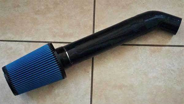
Here's a peek at what the intake looks like:

gamefreakgc-albums-engine-performance-mods-picture59753-3-intake-tubing.jpg


I'll spell out what parts used to build it in another post with more photos.

An important piece I learned is that the MAF signal is very choppy when under heavy load. Take for example this chart:

Red = RPM
Blue = PSIA or boost
Yellow = MAF voltage

i2ZBojW.png


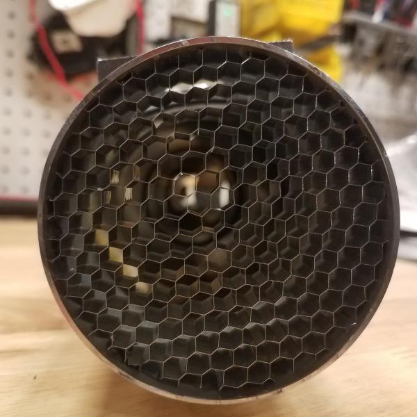
See how the MAF voltage is spiking up and down? That's a sign that I have turbulance at the MAF sensor. The stock airbox only has a single air straightener. I added a "honeycomb" or air straightener to the pipe before the MAF. This will eliminate any turbulence or swirling happening with the intake charge and hopefully smooth out that MAF signal, making it easier to tune and increase power.

gamefreakgc-albums-engine-performance-mods-picture59771-20210115-190122-a.jpg


Lastly, my MAF voltage spikes as high as 4.9 volts. Once it hits 5, it throws a CEL light for out of range voltage value. Can't believe I've maxed out the airflow on a stock MAF sensor without a turbo!
 
Last edited:
The intake is finally on! I wanted to wait until I took some time off from work so I had time to diagnose and tune it.

THmjTVv.jpg

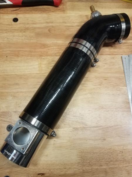
The basics of the intake is this from filter to throttle body:

aFe oiled 8" cone filter: Magnum FLOW Pro 5R Air Filter | aFe POWER
Spectre 3" aluminum MAF housing - comes with adapters to fit DENSO MAF Mass Flow Air Sensor Adapter Kit
3" aluminum air straightener "honeycomb" (see photo in above post) 3.0 OD x .5 Airflow Straightener Screen .187 honeycomb cell mass air flow | eBay
aFe air dam/shield. Essential for keeping hot air away from the filter element so it pulls in cold air from the fender and headlight.
3" diameter silicone tubing, 12" straight section from Intercooler Pipe Fabrication, cut to fit. I cut off around 4"
3" joiner pipe with worm clamps
Silicone port system with brass barb
3" to 2.5" 45 degree reducer

The old 99 intake had an inner diameter of 2.55". Actually a bit larger than I was expecting. The new intake had an inner diameter of 2.89". Some math from 9th grade comparing the surface area difference of the two tubes shows an increase in pipe size of 27.8%. I then create a new tune with a MAF map of 27.8% increase in all values. Reason being is with a larger pipe the capacity is increased but the velocity decreases, meaning the MAF will "see" less airflow than before, even though the engine is still ingesting the same volume of air.

I load up the map and take it for a spin. After 5 minutes it's apparent I'm running rich. After 10 minutes it starts to stumble at idle. After 15 minutes the AFR gauge is wildly swinging from 10 AFR to 18!! I ended up take out about 10% of MAF voltage increase just to get the darn thing to idle. I ended up changing the map to 18% across the board and that gets it to idle and cruise nicely. However it still is running very rich under slight vacuum and low boost. I have it taper off to 10% at the transition zone, or 14.6 PSIA (atmospheric pressure, when the supercharger begins to make boost) and my fuel trims are basically zero.

Tomorrow I hope to tune 3/4 throttle and then full throttle and see what kind of power it makes over my previous intake! I am hopeful that the much larger filter surface area of +80% over the stock aFe oil filter along with a larger, wider and straighter intake tune will make more power!

Shout out to [MENTION=271883]T4topher[/MENTION] who gave me the aFe air dam! It worked out perfectly after widening the opening and drilling a hole for the EVAP hose.
 
Last edited:
Massive Power Gain from 3" Intake

Wow, did this increase power! I'm actually quite surprised at how much it actually gained! Without further ado, the data:

gamefreakgc-albums-engine-performance-mods-picture59862-3in-intake-vs-old-intake.jpg

That's a gain of +43RWHP and +35RWTQ!!! Those are some serious power gains. You'll notice that the power gain is minimal below 4500 RPM, the max I saw was about 10HP. But once the engine hits 4500 everything is up, TQ & HP. I'm very surprised on how much of a difference it made!

Pros: Massive power gain up top. Moderate gains in the power band of 3500-4500.

Cons: Sounds like there's a shop vac in my engine bay now. Also, I can't tell for sure but I think I lost some low-end torque. It's less responsive with throttle than before. Kind of makes sense though as the air is moving slower at lower throttle.

Overall impression: The power gains are much more than I expected. This thing is getting very fast. Now I'm going to try that 2.0" pulley again!

HP Increase:

43HP!!!

Running Total:

+174 HP
:zoom:

On another note, I've officially doubled the RWHP of a stock 4Runner! They were 148 RWHP brand new. It's like I have two 5VZ-FE's stuffed in my engine bay.
 
Upon request, here is my MAF table. It's pretty linear except for 1500 RPM's and below under vacuum. My engine runs a tad bit lean at startup so I've been increasing that value to richen it up. When I first start the engine, the AFR's hover around 13, when before they were closer to 12 - 12.5. Also included my settings for the tune.

FGr1A5l.png


jJdGrJk.png
 
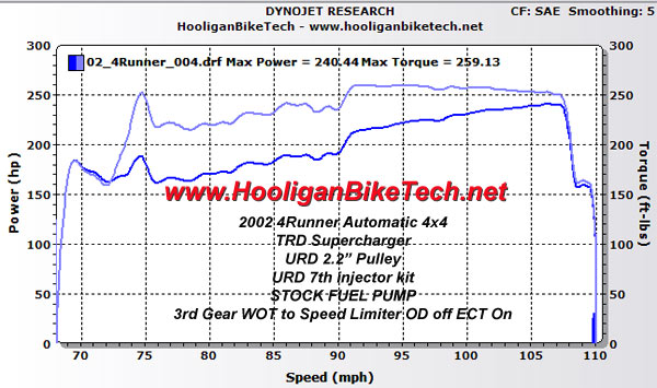
Interesting result! I had someone comment on my Youtube channel that a 5VZFE couldn't' make more than 300rwhp. They were questioning my estimate after adding meth injection and zeroing out the timing map. On a true Dynojet dyno my 2002 auto made 240rwhp and 260rwtq on a 2.2 pulley and 7th injector. It hit the speed limiter or it might have done even better.

Went to a 2.1 pulley and water/meth and zero'd out the timing map which gives me about 7 more degrees of timing so I estimated I was around 300 to the tires now. I'm not sure how much each degree of timing is worth power wise, but I know for a fact on my Hellcat it's 12-14hp per degree. That's a supercharged V8 so probably less on the 4Runner but even if it's only 10 it adds up quick.

projectsportrunnerdyno.jpg
 
Last edited:

Members online

No members online now.

Forum statistics

Threads
278,312
Messages
3,554,089
Members
248,016
Latest member
Advally Service

Trending content

Back
Top