
You are using an out of date browser. It may not display this or other websites correctly.
You should upgrade or use an alternative browser.
You should upgrade or use an alternative browser.
koltlt 97 sr5 build thread
- Thread starter kolelt
- Start date
So I got the new leather shift boot in the mail. It has green stiches 

Also got the TRD caps for the mk6 rims


Started the auto harness repin!!!!


And the final result !!!

You can see the truck running with no check engine light on

So, there is a funny story I have about the repin process. Currently I have the carpet out because I power washed it. And I'm laying down little bit of fatmat, closed cell foam and other things. So I have the factory alarm disconnected. So I go ahead and repin the harness, plug the plugs into the manual pcm and go to start the car. I get nothing. I'm looking back and forth at the chart, at my manual harness that I have for spare and comparing the connectors. Everything is dead on. So I go ahead and repin everything back to auto ! I go ahead and finish and try and start the truck. I get nothing. I start freaking out. Thinking I fried something or I really screwed up. I'm even charging the battery lmfao. Then I'm like, what if I plug in the alarm and try it. And what so you think. It starts up. So I'm like wow!! I go ahead and repin the harness AGAIN! to manual pcm. Plug the alarm back in, and boom everything runs perfectly. So yea, make sure you always have your alarm plugged in. Because it's wired to the PCM. So after 4 repins, sore fingers. It's good.

Also got the TRD caps for the mk6 rims


Started the auto harness repin!!!!


And the final result
!!!
You can see the truck running with no check engine light on

So, there is a funny story I have about the repin process. Currently I have the carpet out because I power washed it. And I'm laying down little bit of fatmat, closed cell foam and other things. So I have the factory alarm disconnected. So I go ahead and repin the harness, plug the plugs into the manual pcm and go to start the car. I get nothing. I'm looking back and forth at the chart, at my manual harness that I have for spare and comparing the connectors. Everything is dead on. So I go ahead and repin everything back to auto ! I go ahead and finish and try and start the truck. I get nothing. I start freaking out. Thinking I fried something or I really screwed up. I'm even charging the battery lmfao. Then I'm like, what if I plug in the alarm and try it. And what so you think. It starts up. So I'm like wow!! I go ahead and repin the harness AGAIN! to manual pcm. Plug the alarm back in, and boom everything runs perfectly. So yea, make sure you always have your alarm plugged in. Because it's wired to the PCM. So after 4 repins, sore fingers. It's good.
I also went ahead and order a new VIPER 2-way alarm. Waiting on that.
Also waiting on gallon of monstaliner!
Also ordered 9-wire cable, and 3 sets of RCA cables for a subwoofer and amp.
Now you may wonder, why 9-wire?, because I am planning on running a 5 channel amp. So I can power a small 10" sub plus 4 door speakers. I don't want anything crazy. So instead of running new speqker wires. You simply run a 9-wire from the amp to the head unit location. And you tap into the factory front left/right and rear left/right positive and negative wires and tape of the wires coming out of the head unit. So in theory you shouldn't need to run any wires and it will save you a headache. I'm pre-running the wires for later.
Also waiting on gallon of monstaliner!
Also ordered 9-wire cable, and 3 sets of RCA cables for a subwoofer and amp.
Now you may wonder, why 9-wire?, because I am planning on running a 5 channel amp. So I can power a small 10" sub plus 4 door speakers. I don't want anything crazy. So instead of running new speqker wires. You simply run a 9-wire from the amp to the head unit location. And you tap into the factory front left/right and rear left/right positive and negative wires and tape of the wires coming out of the head unit. So in theory you shouldn't need to run any wires and it will save you a headache. I'm pre-running the wires for later.
So I wired my (clutch pedal switch) and (cancel clutch button) today. I could have not done this without the help of a fellow member who guided me through the whole process (St Runner).I thank you so much (St Runner)
This is for a 1997 4runner 4x4 with a 5 speed swap. After you have repinned your auto harness to manual PCM.
I don't know if this process is the same for other years.
what you will need:
1)20-22g wire ( I used 18g )
2)Shrink wraps
3)Electrical tape
4)Solder tool
5)Small screw driver
So to start of, you will need to remove the glove compartment and remove the cover that blocks the access to the PCM. it's 3 bolts. Then you will need to remove the connectors that are clipped onto the cover.
Locate this plug, it's on the passenger side , big plug , part of the engine harness.


Go ahead and unplug the grey connector, so you have more slack and room to play with.

Go ahead and remove the pain in the neck , this white clip or whatever you call it. Simply lift on the tab that I am pointing with the screw driver and pull it of. Removing this will allow a lot more room to play with the wire we need. (do not mind the yellow wire, that's the wire I already connected, and later you will to.)

Then unlock the pins on the plug. Not the connector, but the plug/socket. To unlock the pins you need to use a small screw driver to lift up on this : I'm pointing at it with my finger. Each connector, or plug has this. And in order to remove a pin this must be up (unlocked).

Then locate a SMALL, THIN B-R (black-red) wire. It should be next to a small L-Y (blue-yellow) wire. You can see where my screw driver is in. That is where the B-R wire is located. Again, this is on the socket/dash harness part and not the engine harness.

Pin removed. To remove it, remember , you must have the pins unlocked and then you need a small screw driver or something small to push the pin out on the other side. Where the pin is facing.

With this wire, your truck should not start now. So go ahead and try to start the truck. You should get nothing. To make sure you have the right wire, and before cutting things up. I connected a small wire to it, and I grounded the wire. Once you ground that wire/pin, the truck should start. So go ahead and double check everything , before you cut things up or move forward. Again, just hook a wire to the pin you removed and ground the other end.

Once you are sure, that you located the correct wire, go ahead and remove the plug from the clutch pedal. The bottom part of the pedal that is. Should be 2 wires. W-B (white-black),which is GROUND. and B-R(black-red)

Get some more and extend the wires to the correct, desired lenght. Now if you want to wire the Clutch Cancel Button, you will need to solder 3 separate wires. you will solder a wire to the white-black (ground) , you will 2 wires to the black-red. Because, one of the wires, coming from the black-red , it will go across the dash all the way to the passenger side to that plug and to that black-red wire you pulled out. Now the other wire, coming also of the black-red wire of the clutch pedal will be going to the Clutch Cancel Button. The clutch cancel button has 3 wires. white-black (ground) , black-red and black-yellow. The black yellow is the wire that will be connected to a power source 12v and 10amp fuse. Make sure you label your extended wires.

Run your wire across the dash, and before cutting the end of the black-red wire, and soldering. Simply do what I did. Connect a wire to the black-red then another end to your new wire you just ran.

Then go ahead and ground the clutch pedal switch

once you have the clutch pedal grounded, and the clutch pedal connector plugged into the pedal, but your key in and try it. The car shouldn't start. Unless you press the clutch pedal. Once you are sure you have everything wired good. Go ahead and cut the black-red pin and solder your new wire to it.

then shrink wrap it, zip tie, use electrical tape, to clean everything up. And you have successfully aired your clutch pedal switch.
I don't have any pictures of the cancel switch because I ran out of wire to solder to if. But once again, the clutch cancel button has 3 wires. White-black (ground), black-red (which will be the wire you connect to from the clutch pedal that you extended (your second wire you T of) and last wire will be black-yellow which is power source. Need 12v and a 10amp on that line.
After you ran your wire across the dash and solder it to the black-red wire. You should have 2 wires left from your clutch pedal. One is the wire you marked as your ground , which gets grounded. And now you have 1 wire left, which is running of the black-red and this wire will go to the black-red wire on the clutch cancel button part.
This is for a 1997 4runner 4x4 with a 5 speed swap. After you have repinned your auto harness to manual PCM.
I don't know if this process is the same for other years.
what you will need:
1)20-22g wire ( I used 18g )
2)Shrink wraps
3)Electrical tape
4)Solder tool
5)Small screw driver
So to start of, you will need to remove the glove compartment and remove the cover that blocks the access to the PCM. it's 3 bolts. Then you will need to remove the connectors that are clipped onto the cover.
Locate this plug, it's on the passenger side , big plug , part of the engine harness.


Go ahead and unplug the grey connector, so you have more slack and room to play with.

Go ahead and remove the pain in the neck , this white clip or whatever you call it. Simply lift on the tab that I am pointing with the screw driver and pull it of. Removing this will allow a lot more room to play with the wire we need. (do not mind the yellow wire, that's the wire I already connected, and later you will to.)

Then unlock the pins on the plug. Not the connector, but the plug/socket. To unlock the pins you need to use a small screw driver to lift up on this : I'm pointing at it with my finger. Each connector, or plug has this. And in order to remove a pin this must be up (unlocked).

Then locate a SMALL, THIN B-R (black-red) wire. It should be next to a small L-Y (blue-yellow) wire. You can see where my screw driver is in. That is where the B-R wire is located. Again, this is on the socket/dash harness part and not the engine harness.

Pin removed. To remove it, remember , you must have the pins unlocked and then you need a small screw driver or something small to push the pin out on the other side. Where the pin is facing.

With this wire, your truck should not start now. So go ahead and try to start the truck. You should get nothing. To make sure you have the right wire, and before cutting things up. I connected a small wire to it, and I grounded the wire. Once you ground that wire/pin, the truck should start. So go ahead and double check everything , before you cut things up or move forward. Again, just hook a wire to the pin you removed and ground the other end.

Once you are sure, that you located the correct wire, go ahead and remove the plug from the clutch pedal. The bottom part of the pedal that is. Should be 2 wires. W-B (white-black),which is GROUND. and B-R(black-red)

Get some more and extend the wires to the correct, desired lenght. Now if you want to wire the Clutch Cancel Button, you will need to solder 3 separate wires. you will solder a wire to the white-black (ground) , you will 2 wires to the black-red. Because, one of the wires, coming from the black-red , it will go across the dash all the way to the passenger side to that plug and to that black-red wire you pulled out. Now the other wire, coming also of the black-red wire of the clutch pedal will be going to the Clutch Cancel Button. The clutch cancel button has 3 wires. white-black (ground) , black-red and black-yellow. The black yellow is the wire that will be connected to a power source 12v and 10amp fuse. Make sure you label your extended wires.

Run your wire across the dash, and before cutting the end of the black-red wire, and soldering. Simply do what I did. Connect a wire to the black-red then another end to your new wire you just ran.

Then go ahead and ground the clutch pedal switch

once you have the clutch pedal grounded, and the clutch pedal connector plugged into the pedal, but your key in and try it. The car shouldn't start. Unless you press the clutch pedal. Once you are sure you have everything wired good. Go ahead and cut the black-red pin and solder your new wire to it.

then shrink wrap it, zip tie, use electrical tape, to clean everything up. And you have successfully aired your clutch pedal switch.
I don't have any pictures of the cancel switch because I ran out of wire to solder to if. But once again, the clutch cancel button has 3 wires. White-black (ground), black-red (which will be the wire you connect to from the clutch pedal that you extended (your second wire you T of) and last wire will be black-yellow which is power source. Need 12v and a 10amp on that line.
After you ran your wire across the dash and solder it to the black-red wire. You should have 2 wires left from your clutch pedal. One is the wire you marked as your ground , which gets grounded. And now you have 1 wire left, which is running of the black-red and this wire will go to the black-red wire on the clutch cancel button part.

bigdonniebrasco
New member
"Build sponsored by MONSTER"
What a BEAUTIFUL rig!!!! I wish I have 1/2 your skillz
* There is NO way you have a wife or kids!!! And $5 says you live at home!!
I'm just jealous !!!! :bravo:
What a BEAUTIFUL rig!!!! I wish I have 1/2 your skillz
* There is NO way you have a wife or kids!!! And $5 says you live at home!!
I'm just jealous !!!! :bravo:
"Build sponsored by MONSTER"
What a BEAUTIFUL rig!!!! I wish I have 1/2 your skillz
* There is NO way you have a wife or kids!!! And $5 says you live at home!!
I'm just jealous !!!! :bravo:
Is that sarcasm ? I'm a union iron worker. I busted my ass to be where I am.


Got my bussmann 10 relay aux fuse/relay box in the mail. Planning on installing it in back seat where the stock jack goes.

Then I finished up on monstaliner!


Waiting in the mail for new rocker switched, and this plate 1st Gen Tacoma Din Switch plate (6 switch holes) | Paranoid Fabrications
Still have to monstaliner the rock sliders and front grill

Then I finished up on monstaliner!


Waiting in the mail for new rocker switched, and this plate 1st Gen Tacoma Din Switch plate (6 switch holes) | Paranoid Fabrications
Still have to monstaliner the rock sliders and front grill
Nice looking 4runner. I hope to pull off the manual swap on mine in the future, currently have to convince the wife why I want to "fix" it if its not broken.
Haha. What year 4Runner you got?


Freb_mc
New member
Haha. What year 4Runner you got?
1997 limited. starting over fresh. it was stock when I got it.
1997 limited. starting over fresh. it was stock when I got it.
Gotch ya. Hope my information will help you make the swap a easy one !
So today I extended the aftermarket alarm wire harness. I currently have a Viper 3305v installed and the brain is under the steering dash. I'm anal about neatness so after installing I started thinking and I didn't like where the brain of the alarm is. So I went ahead and ordered a harness identical to the one that comes in box when you purchase the alarm. I ordered 2 harness because the original one got cut up and all. The harness ran me $20 each. Reason why I went this way is so i could match the gauge of each wire and the wire color. I think it is much cheaper then buying each wire if you want to have seperate colors. Going to be installing the viper brain under the driver seat on top of the OEM alarm and runing all wires along the OEM alarm wires.

Cut Wires I needed to extended the other harness.

You can see the wires match in color making it easier to reconnect everything later.

Wires extended.

All soldered and shrink wrapped.
Next thing is to move the brains and reconnect everything. The original harness that comes , the wires are to short to reach the proper t-taps where needed. That's why I extended the wires.
Will post the install later

Cut Wires I needed to extended the other harness.

You can see the wires match in color making it easier to reconnect everything later.

Wires extended.

All soldered and shrink wrapped.
Next thing is to move the brains and reconnect everything. The original harness that comes , the wires are to short to reach the proper t-taps where needed. That's why I extended the wires.
Will post the install later
I started wiring the bussmann RFRM 10 relay/fuse aux box. It's a big box. So there's really no space for it under the hood. The box is waterproof. Which is cool if you want to mount it under the hood. But good luck with that. Anyways.... I got tired of knowing that I used a wiring harness to wire my LED lights. Which in reality is ok but sloppy and everything is all over the place. This box eliminates all that. The box is set up like this :
4gauge + wire
4gauge - wire
10/fused relay (12gauge) accessory wires
10/none relay fused (16gauge) wires
10/switch (16gauge) wires
The box originally came with a 8 gauge positive wire. I replaced it with 4gauge welding wire. I used West Marine cable end. They are heavy duty ones. Then I cut small pieces of soldering led and dropped it in the connector, used a blow torch to heat it up and melt the led. While the led was in liquid form I pushed the wire in. Then crimped it down. So it's tight and solid connection. Then used 2 marine grade shrink wraps and some 3m electrical tape to finish it of. Final product is a quality safe cable end. Probably a over kill.
This is the old 8g wire

Here's the new 4gauge


Then I snaked the wire through a opening that's just enough to snake the wires through safely. I snaked the 4gauge and 10 12gauge wires through there. The 4 gauge wire I also put in a plastic wire look with electrical tape to add a layer of extra protection as it will under the metal. And just 3m tape for the 12 gauge.

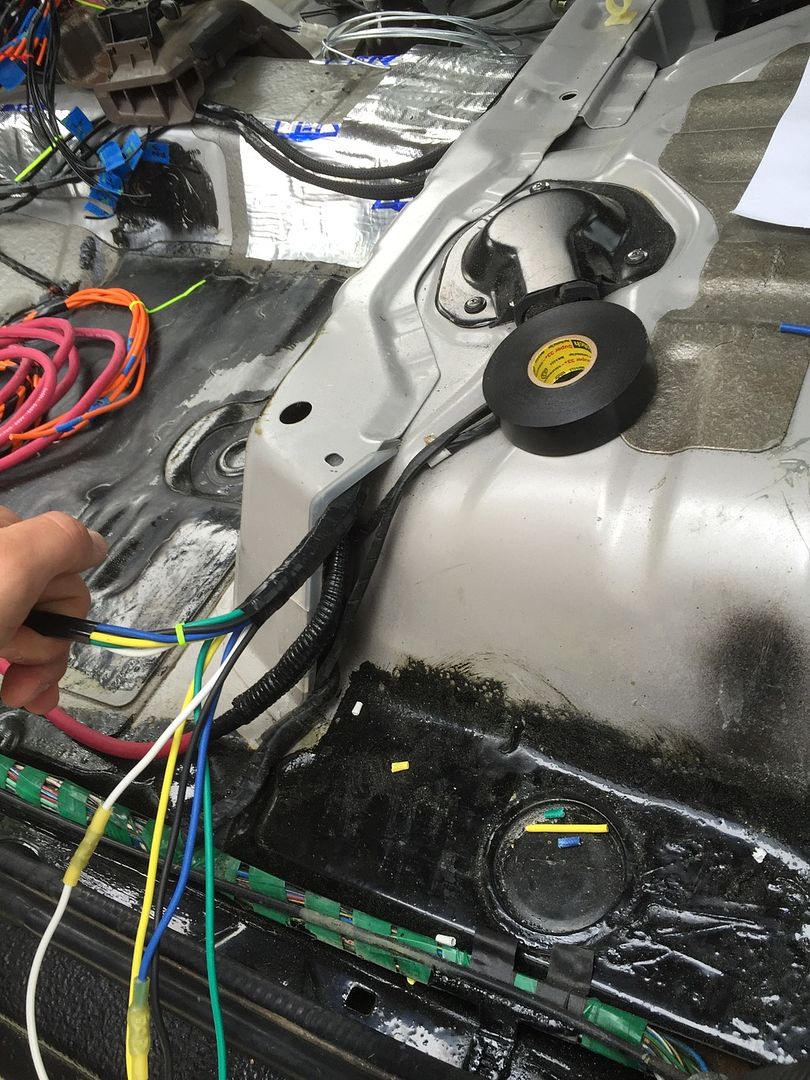
Then I ran the 10 16g switch wires and 10 16g none relay power wires through this opening that's already there. I used some chrome trim pieces to protect the sharp metal edges from messing up the wire. Got it from autozone for about $12


I had to extend all the wires because I ordered the box with short wires like a idiot. Thinking it would fit under the hood. Now I used proper size but connectors and 2 separate marine grade shrink wrap to cover everything up. ( crimps are just as good as soldering. If used proper gauge and proper tools. The way I see it, homes which run way beyond what a vehicle runs , and they don't use no soldering to make connections. So I'm 100% confident )


I divided the switch wires into 2 harnesses. Each containing 5 wires. And the same for the none relay fused power wires. Because these wires are going into the same location and so the none relay fused power wire will be my source of power for the rocker switch which will trigger the relay for the accessory. I used quality 3m electrical tape to tape everything into 1 neat harness.

Here you can see 4 individual harnesses. 2 are switch wires and 2 are none relay fused wires to power the switches. These wires will be running along the center. And into the radio are. I have a 6 hole switch plate that will be under the head unit. Plus later I can add more where ever and the wires will be already there waiting to be used. Eliminating the need of harness.

Then I extended the 12 gauge accessory wire. This set of wire is where the positive wire from your LED light or whatever gets connected to. There is 10 wires, because of 10 relays. Anyways, I divided this set of wires into 2 harnesses. 5 wires going under the hood, and another 5 wires going to the back. This will let me connect 5 accessory from the front of the car. And 5 accessory from the back. For example I have a rear LED light bar. So it's easier to connect it to the rear 12 gauge wires rather then running the led positive wire all the way to the front. And in case I want to hook up anything else, the wires will be there waiting.
Used 12 gauge but connector that has shrink built in.

Then used 3m electrical to seal it more b

5 set of wires all wrapped up in tape. This set is going to the rear.

Wires zip tied and ran to the back.
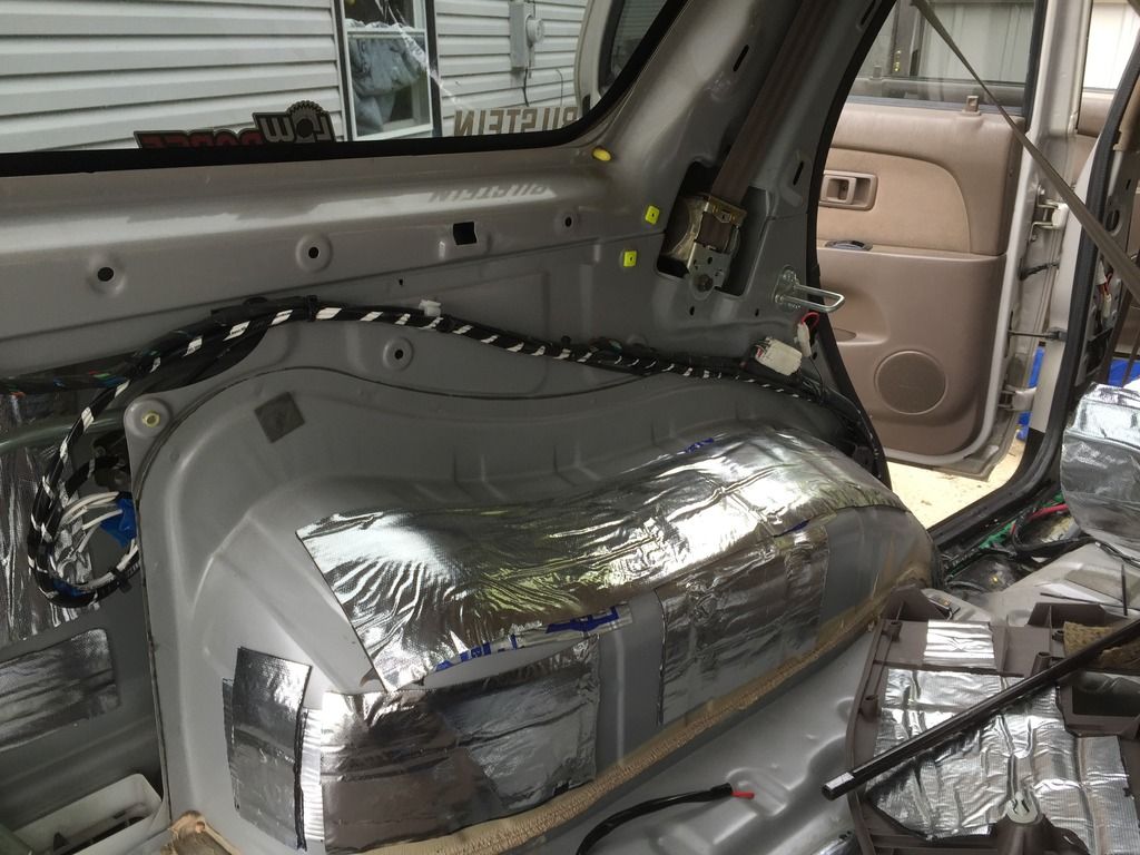
This set of wires are the other 5 set of 12gauge wires. This set will go through firewall under hood. Which I'll use for my windshield led bar and later for CBI dual lights.

I'm not 100% done yet. If I didn't have to extend all the wires and I ordered it with proper length that I needed. It would of saved me a lot of time. But it is what it is.
4gauge + wire
4gauge - wire
10/fused relay (12gauge) accessory wires
10/none relay fused (16gauge) wires
10/switch (16gauge) wires
The box originally came with a 8 gauge positive wire. I replaced it with 4gauge welding wire. I used West Marine cable end. They are heavy duty ones. Then I cut small pieces of soldering led and dropped it in the connector, used a blow torch to heat it up and melt the led. While the led was in liquid form I pushed the wire in. Then crimped it down. So it's tight and solid connection. Then used 2 marine grade shrink wraps and some 3m electrical tape to finish it of. Final product is a quality safe cable end. Probably a over kill.
This is the old 8g wire

Here's the new 4gauge


Then I snaked the wire through a opening that's just enough to snake the wires through safely. I snaked the 4gauge and 10 12gauge wires through there. The 4 gauge wire I also put in a plastic wire look with electrical tape to add a layer of extra protection as it will under the metal. And just 3m tape for the 12 gauge.


Then I ran the 10 16g switch wires and 10 16g none relay power wires through this opening that's already there. I used some chrome trim pieces to protect the sharp metal edges from messing up the wire. Got it from autozone for about $12


I had to extend all the wires because I ordered the box with short wires like a idiot. Thinking it would fit under the hood. Now I used proper size but connectors and 2 separate marine grade shrink wrap to cover everything up. ( crimps are just as good as soldering. If used proper gauge and proper tools. The way I see it, homes which run way beyond what a vehicle runs , and they don't use no soldering to make connections. So I'm 100% confident )


I divided the switch wires into 2 harnesses. Each containing 5 wires. And the same for the none relay fused power wires. Because these wires are going into the same location and so the none relay fused power wire will be my source of power for the rocker switch which will trigger the relay for the accessory. I used quality 3m electrical tape to tape everything into 1 neat harness.

Here you can see 4 individual harnesses. 2 are switch wires and 2 are none relay fused wires to power the switches. These wires will be running along the center. And into the radio are. I have a 6 hole switch plate that will be under the head unit. Plus later I can add more where ever and the wires will be already there waiting to be used. Eliminating the need of harness.

Then I extended the 12 gauge accessory wire. This set of wire is where the positive wire from your LED light or whatever gets connected to. There is 10 wires, because of 10 relays. Anyways, I divided this set of wires into 2 harnesses. 5 wires going under the hood, and another 5 wires going to the back. This will let me connect 5 accessory from the front of the car. And 5 accessory from the back. For example I have a rear LED light bar. So it's easier to connect it to the rear 12 gauge wires rather then running the led positive wire all the way to the front. And in case I want to hook up anything else, the wires will be there waiting.
Used 12 gauge but connector that has shrink built in.

Then used 3m electrical to seal it more b

5 set of wires all wrapped up in tape. This set is going to the rear.

Wires zip tied and ran to the back.

This set of wires are the other 5 set of 12gauge wires. This set will go through firewall under hood. Which I'll use for my windshield led bar and later for CBI dual lights.

I'm not 100% done yet. If I didn't have to extend all the wires and I ordered it with proper length that I needed. It would of saved me a lot of time. But it is what it is.

nc-grayson
Member
wow. your build is entirely over my head and above my pay grade, but I am super impressed!!!
KEEP UP THE GOOD WORK!!!
KEEP UP THE GOOD WORK!!!
wow. your build is entirely over my head and above my pay grade, but I am super impressed!!!
KEEP UP THE GOOD WORK!!!
Thank you sir. But not to be a ass. Why do people keep referring to money. My truck isn't anywhere near to what other members have.
I finished running the amp wire, power wire for fuse box and the switches through the firewall. I really really hope the trim panels go in place. There's a lot of wires on driver side.
nc-grayson
Member
Thank you sir. But not to be a ass. Why do people keep referring to money. My truck isn't anywhere near to what other members have.
I finished running the amp wire, power wire for fuse box and the switches through the firewall. I really really hope the trim panels go in place. There's a lot of wires on driver side.
Just a figure of speech brother...meaning what you're doing is way complicated and above any level of education I've ever had!
Just a figure of speech brother...meaning what you're doing is way complicated and above any level of education I've ever had!
No hard feelings. I was just wondering thanks. I'll keep this posted.
Similar threads

- Replies
- 2
- Views
- 3K
- Replies
- 0
- Views
- 2K

- Replies
- 2
- Views
- 2K
- Replies
- 4
- Views
- 6K


