lets see your interior mods

Hacked the front and rear cubby holes to be a wee bit more functional.


f9jQEYih.jpg


UxBV4xHh.jpg
Where did you get the panels to cover the openings in the dash and cargo area? Are these custom made?

Sent from my S61 using Tapatalk
 
Just added this little thing this morning after finding it in a box while sorting stuff for the upcoming move. We were issued these before deployment and it came in very handy then! Should serve well as a posable maplight/personal light. It's the MLPS from Princeton Tech:

d8Hd1TE.jpg


X2TLpU9.jpg
 
Just added this little thing this morning after finding it in a box while sorting stuff for the upcoming move. We were issued these before deployment and it came in very handy then! Should serve well as a posable maplight/personal light. It's the MLPS from Princeton Tech:

d8Hd1TE.jpg


X2TLpU9.jpg
What happens during an airbag deployment? Remember that the trim covers a portion of the side curtain airbag and disconnects during the deployment, possibly aiming that light as a projectile directly towards you - or perhaps the clip could keep the trim from disengaging as intended or even puncture the inflating airbag.

I apologize, but my job is to expect the unexpected, so I see something like this and say "cool.... what can go wrong?"
 
What happens during an airbag deployment? Remember that the trim covers a portion of the side curtain airbag and disconnects during the deployment, possibly aiming that light as a projectile directly towards you - or perhaps the clip could keep the trim from disengaging as intended or even puncture the inflating airbag.

I apologize, but my job is to expect the unexpected, so I see something like this and say "cool.... what can go wrong?"

I like to live dangerously.


Seriously though, it's a good point. I clipped it onto the sun visor panel I have and that seems like a better position for the light anyway, being directly above instead of angled.
 
What happens during an airbag deployment? Remember that the trim covers a portion of the side curtain airbag and disconnects during the deployment, possibly aiming that light as a projectile directly towards you - or perhaps the clip could keep the trim from disengaging as intended or even puncture the inflating airbag.

I apologize, but my job is to expect the unexpected, so I see something like this and say "cool.... what can go wrong?"

from his sig, he likes to jump out of perfectly good airplanes......so he gets a pass..
 
Any chance you printed or saved Old Red's instructions for this? His thread was shut down by the mods.

I looked thru my old files and I don't see the instructions, sorry. Why did they shut the thread down? Because some other person wanted the business? Ive seen that before on other forums. So unfair and unreasonable that in America you cant sell a good product for cheaper
 
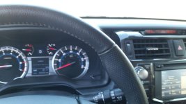
Here is my best interior mod. Upper right hand corner of pic where clock used to be.
 

Attachments

  • 20180717_104119.jpg
    20180717_104119.jpg
    122.3 KB · Views: 2,566
I looked thru my old files and I don't see the instructions, sorry. Why did they shut the thread down? Because some other person wanted the business? Ive seen that before on other forums. So unfair and unreasonable that in America you cant sell a good product for cheaper

It was really unfortunate. "ALL" his threads was shut down except for the group buy one, which is closed for comment.

you can read up on what happened here:

TRD Pro Side Mirror Swap/Upgrade
 
Here is my best interior mod. Upper right hand corner of pic where clock used to be.

any chance you saved or printed the instructions for the swap. Old Red's thread is no longer available at least not with pics.

need the pics that correspond to this steps:

18.) Next step involves inserting the blue and grey wires into connector G13. See below to find connector G13


19.) We need to undo the connector terminal locking mechanism on connector G13 to be able to easily insert the two terminal into their respective spots on the connector. Use the small screw drive and gently pry at the locations shown in the photo below. The locking mechanism only comes up a small way, so if it is slightly raised off of the surface like the second photo below, you did it.


20.) Next step is to insert the right color wires and terminals into the correct spots. Go slow here because if you put it in the wrong spot, they are an absolute PITA to get back out, and nine times out of ten, you will break something trying to get them back out. So, again slow and steady wins the race. These terminals are keyed to only go in one way. If you are having resistance inserting it into the connector, rotate it 180* and try again. You will see there is a small tab standing upon the metal part of the connector. This goes into the notch in the opening of the terminal hole in the connector. Match up the location of the wires to the photos below and insert them all the way until you hear a small click. Once the wires are in correctly, you can press down on the connector terminal lock, and insert G13 back into the connector it came out of.


21.) Now all that is left to do is to route the rest of the harness as shown below to meet with the instrument cluster connector.


22.) We can now use the small self sealing silicone tap to "tap" into the already present LIN Bus. You will want to take it slow here because improper tapping will give you a display with little to no info. The harness will already come with this tap on the green wire. You need to slip the LIN Bus wire (see image below) on the instrument cluster connector into the empty slot on the side of the tap. Make sure the LIN Bus wire is fully seated in this slot so that the internal metal tap will be able to come down and make contact with the wire. Once you have this properly in place, press down on the tap with the pliers and make sure it comes down evenly on both sides.
 
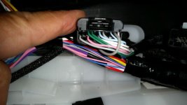
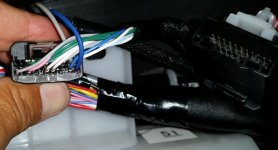
Apologies in advance for the size. I don't recall where I was in the steps when I took these. But I took them to show which slots the wires went into. The wires I am working with are the grey and blue ones that do not "flow" with the cables.
 

Attachments

  • 20180710_192650.jpg
    20180710_192650.jpg
    31.1 KB · Views: 2,774
  • 20180710_192728.jpg
    20180710_192728.jpg
    37.8 KB · Views: 2,739
Apologies in advance for the size. I don't recall where I was in the steps when I took these. But I took them to show which slots the wires went into. The wires I am working with are the grey and blue ones that do not "flow" with the cables.

Thank you. Just got a reply from Old Red with the whole instructions. Appreciate you responding to my question.
 
Where did you end up getting the part? I've seen plenty of the older orange ones but haven't been able to find a blue one...

Is there a link that is operational to this one? The link provided is dead. Just curious if there is also a harness available to purchase so as I can do this mod.

Edit: This was being quoted to the (2015+ Accesory meter display harness that replaces the individual clock on the newer 4runners)
 

Members online

Forum statistics

Threads
278,309
Messages
3,554,075
Members
248,016
Latest member
Advally Service

Trending content

Back
Top