Need help with turn signal issue

kishanSR5

New member
I recently removed my factory front bumper and turn signals and am now a set of 6" oval sequential trailer turn signals for the front of my truck. They are 3 wires coming off the light itself; tail, ground, and stop & turn. I have the ground and stop & turn wires hooked up to the factory turn signal wires. And it does flash however it doesn't flash properly. Does anyone know of a way to fix this?
Here is a video of how it flashes.
 
Register to hide this ad
If you've gone all LED you're going to need some resistors added somewhere in the system.

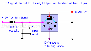
That might work yeah. I also tested the lights with a constant 12V source (wire connected from the battery to the light directly) and they blink sequentially just like they are supposed to. No half flashes or anything. So what I think I need to do for both sides is create some sort of harness with a relay that uses the turn signal power wire as a signal wire and deliver a constant 12V to the turn signal while the turn signal is active.
 
I just ordered a pair of resistors and they should be coming in monday. So I'll do some testing then and post what happens
 
I believe that light is designed to receive a constant 12v, not the flashing sequence of a standard turn signal. Also, no need to add resistors, you can modify your flasher by cutting the "bulb out" hyper flash function. I'll try to get the link here in a bit.
 
I believe that light is designed to receive a constant 12v, not the flashing sequence of a standard turn signal. Also, no need to add resistors, you can modify your flasher by cutting the "bulb out" hyper flash function. I'll try to get the link here in a bit.

Well I guess it's a bit too late because I ordered the resistors but yeah they are designed for a constant 12V. I would really appreciate any help on getting this to work properly.
 
Go to the flasher relay and jam a wire in to the input feed for the relay, that should be s constant signal.
 
Here is a link to convert your turn signal flashing to a constant output. It is designed for a clearance lamp, but will work fine for what you want.

Special Applications with SPDT Relays, Diagrams

:blah:

Ah ok. So I'm guessing the diagram I am supposed to look at is the one "Pulse to Steady Output"? And based on that diagram I need to find the wire that provides a 12v signal to the flasher relay and create a parallel circuit with that wire using a capacitor and resistor ?
 
Ah ok. So I'm guessing the diagram I am supposed to look at is the one "Pulse to Steady Output"? And based on that diagram I need to find the wire that provides a 12v signal to the flasher relay and create a parallel circuit with that wire using a capacitor and resistor ?

turninglights.gif


No, just run the flashing(pulse) turn signal circuit to the capacitor in that circuit.

:keyboard:
 

Members online

No members online now.

Forum statistics

Threads
278,309
Messages
3,554,075
Members
248,016
Latest member
Advally Service

Trending content

Back
Top