Look at this thread (post):
http://www.toyota-4runner.org/engin...me-help-navigation-install-19.html#post133362
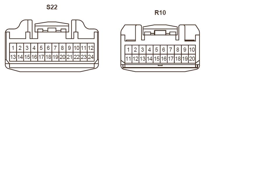
R10 (back of OEM NAV unit) and S22 (back of AMP)
So.. From Connector:
R10 Pin 11 - S22 Pin 23
R10 Pin 12 - S22 Pin 22
R10 Pin 13 ---SHIELD.
My take is that your connect the first 2 wires, then with a shield'ed wire you connect to Pin13 (on R10) and RUN the wire back to the amp and connect to NOTHING. I read this in a Tundra forum but I can't find the post.
Hope this helps.
I'll be embarking on this very soon as I'm getting extremely frustrated on not having these features hooked up yet.
So, I'm a little late to the posting party, but I thought I'd update this thread in case the info helps anyone searching through old threads for info (like me -- I found this thread while searching for info on how to add an IPOD lightning connector input to my E7008 Radio through either the "aux" input or the "SAT" input).
So I went ahead and did this and it did not work for me.
I used three wires, stripped the sheath off one, and made my own shielded wire. I wrapped it around pins 11 and 12, and used oem connectors for the Toyota harnesses. I connected it as required and saw no difference. Either I wired it wrong, which I doubt, or my wiring is correct and I'm missing something minor. Whatever the reason, I'm beyond frustrated that it's not working. Getting tired of taking apart my dash.
I found
this thread that [MENTION=50507]CookieRoe[/MENTION] contributed. Wonder if tapping into that corner they spoke of will help
So, here's my explanation of the pin 13 shield...
Use something like this:

It is intended to by an aluminum foil type of wrapper around the two signal pins, or a braided wire mesh.
The idea is that noise will interfere with the two signal wires if they are not shielded. So you wrap a metal jacket around those two wires (without making electrical contact with them) and this will provide a "shield" to pick up any stray signals in this wrapping. You connect it to pin13 on the radio head unit -- and pin 13 will most likely be grounded somewhere internally to the radio case... because that's how shielding works best) so any stray signals get captured by the shielding and transferred to the radio case, which is all "around" your signal. This way you don't get interference with the intended signal on the two interior wires.
So you may ask, why isn't this "shield" also connected to the amp?
Good question! The answer is to prevent what are called "ground loops".
Because the head unit and amp are both grounded to the car chasis, AND because they are physically far away from each other, if you connected this shield to both the head unit's grounded case AND the amps grounded case, you are likely to have slight voltage differences between the Head Unit, and the amp, and this difference could cause a small (sometimes erratic) current to flow through the shield, which would in turn produce noise such as a hum or pick up an alternator wine.
So you use a shield wrapped all the way around the signal wires, but you only ground it to the head unit (via pin 13) and let it float at the other end.
Now, when interference -- in the form of a magnetic field -- crosses the bundle of two signal wires surrounded by the shielding mesh or foil, the idea is that the magnetic field will induce a current... but only in the shield, and that current can be "drained" through pin 13 which is grounded to the chasis through the head unit.
The theory is that this will protect the wires inside the shield from picking up noise, because those signal wires will not be affected by noise from the magnetic field.
You only do this type of setup in situations where noise IS a problem, and then you do this solution as an attempted "fix" to stop the noise. If you don't experience noise in the first place, then you don't bother with this technique.
Below are a few quotes that I found on an Electrical Engineering board.... I guess you could say that that I like this stuff..
Source:
Shielding -- Is it effective when floating? - Page 1
(quote 1)
Suppose your cable has a floating shield. That means that it will act as a receiving antenna for any radiation intersecting it. As an antenna it will therefore experience induced voltage changes. The wires inside the shield are in close proximity to it, so that they form a capacitor with the shield. So if the shield experiences voltage changes, the wires inside the shield will experience electrostatically induced voltage changes in sympathy. The shield is letting things through.
By tying the shield to an appropriate part of the circuit this effect is reduced. Now the whole system changes in voltage when the shield acts as an antenna and so differential voltages between the shield and the circuit are minimized.
What the shield is basically doing is acting as an equi-potential bonding system. It shorts out any induced differences in voltage along the length of the cable, and it shorts out any differences in voltage between the outside and the inside.
(end qoute 1)
(quote 2)
n answer to your question, yes, shielding is effective when floating. It might be more effective when grounded to your circuit ground, but it still is effective even if floating.
First, I work with a handheld wireless device for my job, and if I bring a piece of metal close to the antenna, it definitely changes the signal coming off the antenna.
Second, we have a shield room / anachoic chamber, and if you go in there, and close the door, your cell phone loses all communication with the outside, ie no 3g, no wifi, no bluetooth unless it's within the chamber. It is not grounded to your phone, but it certainly works well.
Third, when we were getting one of our products tested for FCC certification, it failed because a microcontroller (ATTINY44 to be precise) in a QFN package was radiating too much noise (RF). So I took a piece of copper tape, cut it to a square just smaller than the package, and stuck it to the top of the microcontroller. It was not grounded, in fact it was not connected to anything, just stuck to the plastic case, and it reduced the emissions enough to bring the product into compliance.
With regards to your other question, why is grounding the shield useless if the signal is not grounded. It's been answered, but I'll try to state it a different way. Connecting the shield to any potential that is not referenced to the signal of interest in some way (ie the ground of your circuit of interest), is like not connecting it to anything. You could connect the shield to earth ground, or to a computer's ground, or to a cow. There's stil no connection to your circuit, and thus it doesn't change how the shield behaves with regards to your circuit.
Hope that clears things up.
- Erik
(end quote 2)
Cheers!
-Phil