
OEM rear camera wire diagram?

CookieRoe

Senior Member
Hey All,

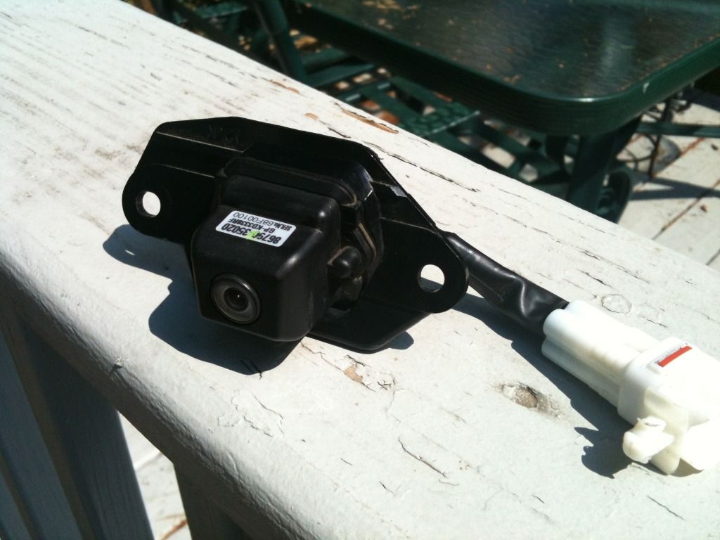
On my never-ending quest to install everything, I bought an OEM rear camera for my 2005 4Runner (Toyota Part #: 86790-35020). I have the pin outs for the NAV (see below), but I've found nothing on the wires on the actual camera. Anyway, many use aftermarket cameras and that's probably why there isn't much info. So then, 4 wires on the camera, they are White, Black, Red and Yellow.

please correct me if I'm wrong, :)

White: Camera Ground (negative): CA-
Black: Video Ground (negative): V-
Red: Camera (positive), Power (6V): CA+
Yellow: Video (positive), video signal: V+


These colors are "the most logical" to me, but I've found conflicting info on Lexus/Toyota forums. So I just connect everything and viola? I've read on other forums that the grounds need to be connected together (CA- and V-) or to the body. If anyone can clear this up for me, that would be great!

33602d1285706975-5th-gen-navigation-wiring-info-nav-radio-connector-pinouts-002.jpg~original


null-1.jpg~original
 
Register to hide this ad
Cool, you used my ECU terminal diagram! I didn't think anybody looked at that LOL.

The power ground definitely goes to body ground, however, if you take the video ground to the body, you either won't have video as you won't have a complete circuit, or it'll be a horrible picture as there will be all sorts of noise on it. Take the video directly from the camera to the nav unit.

When I did mine, I actually connected acc power to the camera, so it is powered at all times. I did that so I could switch to the camera while still moving forward, as it obviously wouldn't get the "transmission in reverse" turn-on signal voltage. Of course, if you have no desire to do that, simply tap the reverse lights for power.

I have since changed out the OEM to an aftermarket and still use the camers. I do like having the ability to check the camera while moving forward. If you want this feature, but don't want it wired to acc, you could also wire up a relay system to only supply power when you select it.

I'll shoot a pm your way to answer your other questions from your pm. Let me know if you have any other questions and I'll try to help.
 
Cool, you used my ECU terminal diagram! I didn't think anybody looked at that LOL.

I'll shoot a pm your way to answer your other questions from your pm. Let me know if you have any other questions and I'll try to help.

A/V1, that diagram is the best "pinout" there is out there. Thanks! :bigok:

Looks like Red is +
White is CA-
Black +
Yellow -

someone correct me if I'm wrong.

Hmmm, so according to you, the Black and Yellow I have mixed up. Ok, I'll reverse it to your specs and see if that works when I get it installed. I'll report back. THANKS! :thanks:
 
Reviving an old thread ....

The confusion with that diagram is that the camera module itself has a short pigtail of wire that leads to its integrated connector, T11. The wire colors shown in the diagram are those of the 4 different harnesses that carry the signals to the head unit, not those on the T11 pig tail. Pairing up the pin numbers on T11 to the corresponding wire colors on the Back Door Wire No.2 Harness and you get the following.

Code:
[U]Camera (T11) Pin/Color[/U],   [U]Harness Wire Color[/U],   [U]Signal[/U]
Pin 1/Red,                Red,                  CA+ (6V)
Pin 2/Black,              White,                GND
Pin 3/White,              Brown,                V-
Pin 4/Yellow,             Black,                V+
 
Last edited:

Members online

Forum statistics

Threads
278,310
Messages
3,554,080
Members
248,016
Latest member
Advally Service

Trending content

Back
Top