
You are using an out of date browser. It may not display this or other websites correctly.
You should upgrade or use an alternative browser.
You should upgrade or use an alternative browser.
Performing the "Big 3" Wiring Ugrade on a 3rd Gen T4R - A How To
- Thread starter BigFishAllDay
- Start date

Wire #6 continues up the fender well as a single wire, and is routed to its destination at the passenger side fender, where it is secured with a bolt to create the second of the "Big 3" connections, the "Engine Block (Alternator) Ground > Chassis Ground" connection. This provides a second ground path between the Alternator/Engine Block grounds and the vehicle's chassis, WITHOUT forcing the ground current to travel through the TINY stock Wire #5.
BFAD, is that correct? Or didn't you actually route Wire #6 and ground it to the driver side fender?

BigFishAllDay
New member
[MENTION=74598]hrt4me[/MENTION] good eye!
Thanks for proof reading. Although the picture clearly shows #6 terminating at the D/S, I guess the words should match the illustrations. Fixed!
Thanks for proof reading. Although the picture clearly shows #6 terminating at the D/S, I guess the words should match the illustrations. Fixed!
these specific posts helped me the most when I finally completed my own Big 3 Wiring Upgrade earlier this afternoon
I then hooked up two of the Big 3 wires at the alternator side. The NEW Engine to Chassis ground (Wire #6) can be connected anywhere on the engine block to anywhere on the vehicle's chassis. Since the alternator case is the ultimate grounding point of the entire electrical system, I decided to hook up right to the alternator mounting bracket where I would be electrically closest to the alternator case. You can see the connection to the alternator mounting bracket at left (Wire #6, also notice the bent terminal, which I had to do to keep the wiring out of the path of the alternator drive belt),
The second connection was at the (+) Charging Post on the alternator. You can see the connection to the alternator charging post at center (Wire #8). The wires have been labeled according to the initial diagram at the top of the write-up.
Also, you can observe in the picture how the Alternator charging post now has TWO wires connected two it - Wire #8 AND Wire #3, as labeled in the photo.


Topside, near the battery, things look like so:
Wire #8 continues up the fender well, where it feeds into a 120A circuit breaker. On the other side of the circuit breaker, Wire #8 continues on to connect to the (+) battery terminal. This completes the first of the "Big 3" connections, the "Alternator Positive to Battery Positive" connection. This provides an alternate path for the Alternator to send a charging current to the battery. The new path is again, made of 4ga. wiring, which has a current capacity of 150A. I chose to put a circuit breaker on this path for the same reason I choose to fuse all of my power connections for aftermarket electronics.... safety and fire prevention.
Wire #6 continues up the fenderwell as a single wire, and is routed to it's destination at the driver side fender, where it is secured with a bolt to create the second of the "Big 3" connections, the "Engine Block (Alternator) Ground > Chassis Ground" connection. This provides a second ground path between the Alternator/Engine Block grounds and the vehicle's chassis, WITHOUT forcing the ground current to travel through the TINY stock Wire #5.
Wire #4 is left intact, providing a redundant Engine Block > Chassis ground by flowing ground current from the engine block to the battery (-) terminal, across the terminal, and to ground via the new Wire #7.
Wire #7 REPLACES Wire #5, creating the third of the "Big 3" connections, the "Battery Negative > Chassis Ground" connection. By replacing the wimpy stock Wire #5 with a much larger and higher capacity Wire #7, we have strengthened the stock ground path from Engine Block > Chassis ground across Wire #4, AND created a much stronger ground path for all of the chassis wiring (ECU's, lighting, windows, radio, etc, etc) back to the battery.
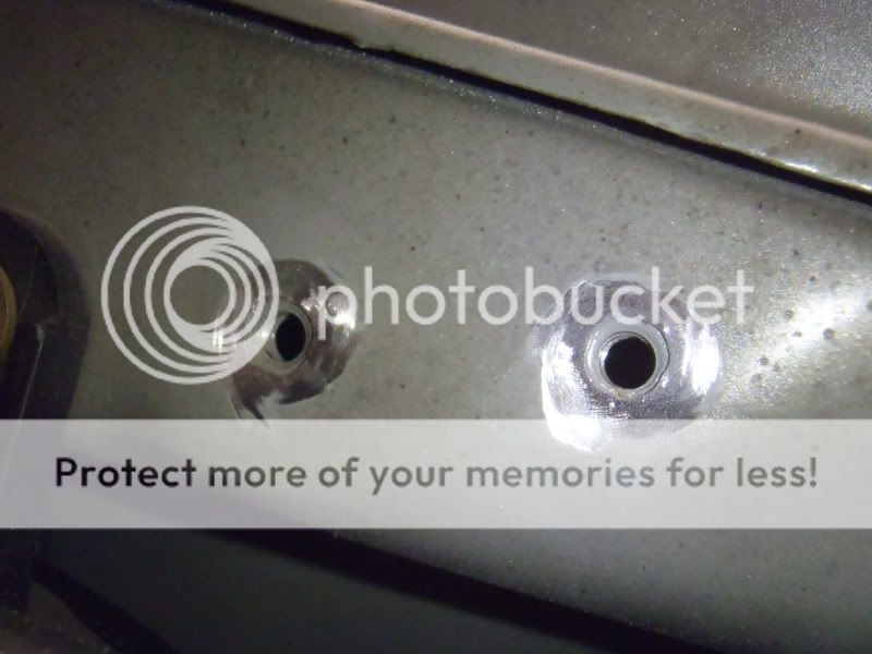
Last but not least, I removed the paint from the metal at the two fender ground points for Wire #7 and Wire #6, to ensure that they would have a clean and solid connection to the chassis. I ended up using the stock ground location, and another unused bolt hole located about 2 inches rearward.

infamousRNR
Senior Member
can you leave the stock wiring in place and just simply add the larger gauge wire? so it would have addition connections. not replacing, just adding.? [MENTION=44220]BigFishAllDay[/MENTION]


BrianSD_42
New member
If you re-read the thread(s) you will see that we all left the stock wiring in place with the exception of the batt (-) to chassis cable which is replaced entirely.
I posted a bunch of pictures as well.
I posted a bunch of pictures as well.

MTD
New member
I'm gearing up right now to do my dual battery install so I figured that I would take a look and see how much more work it would be to just go ahead and do the "Big 3" mod in one fell swoop. I have just a couple questions:
1. I know its called the big 3, but what gauge is the wire between the alternator and battery stock? I think for my case I will forgo adding and unnecessary circuit since I don't have a ho alt.... yet....
2. Why wouldn't we just replace wire #4 & #5 with some 2 awg and call it good and not clutter the engine bay any further. ( in my case i guess..)
3. Also why crimp the lugs if you are soldering really no need...
Any insight on this two things would be good help. I know for sure right now that I will be upgrading my body ground but if anyone has a compelling reason to do all three right away I will.
PS: this is the battery I picked up for my auxiliary
Amazon.com: Odyssey 31M-PC2150ST-M TROLLING Thunder Marine Dual Purpose Battery: Automotive
1. I know its called the big 3, but what gauge is the wire between the alternator and battery stock? I think for my case I will forgo adding and unnecessary circuit since I don't have a ho alt.... yet....
2. Why wouldn't we just replace wire #4 & #5 with some 2 awg and call it good and not clutter the engine bay any further. ( in my case i guess..)
3. Also why crimp the lugs if you are soldering really no need...
Any insight on this two things would be good help. I know for sure right now that I will be upgrading my body ground but if anyone has a compelling reason to do all three right away I will.
PS: this is the battery I picked up for my auxiliary
Amazon.com: Odyssey 31M-PC2150ST-M TROLLING Thunder Marine Dual Purpose Battery: Automotive
Last edited:
BrianSD_42
New member
I used crimp ends and put sauder in it for an extra strong connection.
I used 4 G Copper (in some cases CCA). I don't see the need for 2 or 1 gauge that's overkill. But 8 gauge would be too little.
If you are doing a dual battery setup then you may want to read some other threads. I don't know how the big three will affect your plans. Personally I don't think a dual battery is necessary. Its complicstedt and expensive.
Why not just run a single battery setup and add a dual battery only for trips.
I used 4 G Copper (in some cases CCA). I don't see the need for 2 or 1 gauge that's overkill. But 8 gauge would be too little.
If you are doing a dual battery setup then you may want to read some other threads. I don't know how the big three will affect your plans. Personally I don't think a dual battery is necessary. Its complicstedt and expensive.
Why not just run a single battery setup and add a dual battery only for trips.
MTD
New member
I used crimp ends and put sauder in it for an extra strong connection.
I used 4 G Copper (in some cases CCA). I don't see the need for 2 or 1 gauge that's overkill. But 8 gauge would be too little.
If you are doing a dual battery setup then you may want to read some other threads. I don't know how the big three will affect your plans. Personally I don't think a dual battery is necessary. Its complicstedt and expensive.
Why not just run a single battery setup and add a dual battery only for trips.
I got the whole dual battery thing sorted, It is not a very complicated mod kind of like the Big 3 mod. I was blessed enough to get the battery free and that was the expensive part... I think with parts I am a total of 150 bucks into it buying only Blue Sea Systems, the best, parts.
I can justify it because with as many times as I have killed my battery while camping/bonfire parties (cut me a break im a college kid
 ) it will save me from having to call someone to jump me.
 As far as soldering/crimping goes I use the lug solder pellets and with them there is no need to crimp looks cleaner too. I am going run 2 awg to the battery in the rear and will end up making some additional grounds I think to help ground the back battery using the 2 ga as well.
And after all that I am still on the fence about doing the rest of the big 3 lol. :keyboard:
BrianSD_42
New member
3. Also why crimp the lugs if you are soldering really no need
Unless you are using a clamp of some kind then yes you need to crimp. The crimp makes the attachment of wire to metal end connector MUCH stronger.
Solder is not very strong and not a weld. It is not meant to hold things together.
Also, my end connectors had a smooth internal surface and that also makes the solder not hold very well. I'm surprised you don't realize this. Perhaps there is something I don't know about your plan.
The crimp is to hold the wire to connector so you can pull on it with 50+ lbs of force (say a loose battery) and the cable won't come apart from the connector.
I've actually had a loose battery before and the cables were strong enough to hold it in place because of their end connectors. If the cable end connectors had come apart (because for example you didn't crimp them) they might cause an electrical fire.
Maybe you are using different connectors but if you are using the ones in my pictures above then be smart and crimp them.
Last edited:
MTD
New member
Unless you are using a clamp of some kind then yes you need to crimp. The crimp makes the attachment of wire to metal end connector MUCH stronger.
Solder is not very strong and not a weld. It is not meant to hold things together.
Also, my end connectors had a smooth internal surface and that also makes the solder not hold very well. I'm surprised you don't realize this. Perhaps there is something I don't know about your plan.
The crimp is to hold the wire to connector so you can pull on it with 50+ lbs of force (say a loose battery) and the cable won't come apart from the connector.
I've actually had a loose battery before and the cables were strong enough to hold it in place because of their end connectors. If the cable end connectors had come apart (because for example you didn't crimp them) they might cause an electrical fire.
Maybe you are using different connectors but if you are using the ones in my pictures above then be smart and crimp them.
If you solder using my technique you don't need to crimp, and I have hung batteries using this technique. The lugs that i buy are tinned so the solder sticks them, they arnt going anywhere. I may make a destructive test video for sh1ts and grins to show how much it can hold. Typically I have only seen people who don't what they are doing when it comes to wiring crimp and solder, there is just no need. (in pretty much all cases, there is always the couple exceptions)
Solder is meant to hold things together actually as well any professional install of sound systems, alarms, or even aftermarket truck parts will tell you that SOLDER and heat shrink all of their wires. Crimping is by no means the end all way to connect electrical components.
https://www.youtube.com/watch?v=zssIlnwH8dY
https://www.youtube.com/watch?v=SXDkNMDDrBs -From the company that makes the lugs...
https://www.youtube.com/watch?v=7BEPxU87EvA
https://www.youtube.com/watch?v=y5vkwWuDRGE
Last edited:
BigFishAllDay
New member
1. I know its called the big 3, but what gauge is the wire between the alternator and battery stock? I think for my case I will forgo adding and unnecessary circuit since I don't have a ho alt.... yet....
2. Why wouldn't we just replace wire #4 & #5 with some 2 awg and call it good and not clutter the engine bay any further. ( in my case i guess..)
3. Also why crimp the lugs if you are soldering really no need...
I would answer your questions, but from what I can tell, all three of them are rhetorical. Also, judging by your exchange with Brian you seem to believe that you have all the right answers.
That being said, good luck, and take my write-up for what it is... an account of my experience/methods/opinions and nothing more.
BrianSD_42
New member
I'd also like to add to my earlier comments that I don't necessary think it is wrong to not crimp it, you're not wrong per say.
Its just that there is good logic behind crimping it and its important that whomever reads this it told that.
Its just that there is good logic behind crimping it and its important that whomever reads this it told that.
MTD
New member
I would answer your questions, but from what I can tell, all three of them are rhetorical. Also, judging by your exchange with Brian you seem to believe that you have all the right answers.
That being said, good luck, and take my write-up for what it is... an account of my experience/methods/opinions and nothing more.
Very good point lol, I guess i was just looking for peoples thoughts on it really. your write up though was spot on though! A really big help
I'd also like to add to my earlier comments that I don't necessary think it is wrong to not crimp it, you're not wrong per say.
Its just that there is good logic behind crimping it and its important that whomever reads this it told that.
I agree, and I apologize for being bull headed about it.
Hi All,
In prepping to do the Big 3... I have come across a few issues. Any input is appreciated.
1) The biggest issue
This is my current setup:

In prepping for the Big 3, I purchased the 'Marine' terminals, and hooked them up. There are 2 major problems:
A) The wires on the left (or positive side) do not move an inch from their spot. This makes it impossible when trying to pull them up to be able to push them down on the positive vertical screw. Is there just a zip tie or tape or something holding them from moving, anyone else experience this? [MENTION=65101]BrianSD_42[/MENTION], you have a 97 like me, any issues with this when you did your Big 3?
Here's a visual:

B) I noticed the cables don't even fit the positive screw even if the cables were able to move freely. I'm guessing I purchased the wrong one? This positive one from the link above is limited, I believe to 3/8 and 5/16 on the negative per the link description.
This is the 'marine' terminal I purchased:
Super Start® 08507 - Marine Battery Terminals | O'Reilly Auto Parts
2) Side point assuming I knock out the issues with #1 above... on a practice wire, I tried to replicate putting cut up pieces of rosin solder in the metal battery lug in a C-clamp and putting a torch on it as BFAD did. The solder melts into hardness with the mini-torch instantly, so when you put the cable in, you are just pushing against hardened solder. You can't crimp anything at that point. Is it the weakness of the $10 mini-torch or a bad brand of solder? I'm guessing it's the cheap-o torch not heating the solder up enough, but just wanted to confirm.
In prepping to do the Big 3... I have come across a few issues. Any input is appreciated.
1) The biggest issue
This is my current setup:
In prepping for the Big 3, I purchased the 'Marine' terminals, and hooked them up. There are 2 major problems:
A) The wires on the left (or positive side) do not move an inch from their spot. This makes it impossible when trying to pull them up to be able to push them down on the positive vertical screw. Is there just a zip tie or tape or something holding them from moving, anyone else experience this? [MENTION=65101]BrianSD_42[/MENTION], you have a 97 like me, any issues with this when you did your Big 3?
Here's a visual:
B) I noticed the cables don't even fit the positive screw even if the cables were able to move freely. I'm guessing I purchased the wrong one? This positive one from the link above is limited, I believe to 3/8 and 5/16 on the negative per the link description.
This is the 'marine' terminal I purchased:
Super Start® 08507 - Marine Battery Terminals | O'Reilly Auto Parts
2) Side point assuming I knock out the issues with #1 above... on a practice wire, I tried to replicate putting cut up pieces of rosin solder in the metal battery lug in a C-clamp and putting a torch on it as BFAD did. The solder melts into hardness with the mini-torch instantly, so when you put the cable in, you are just pushing against hardened solder. You can't crimp anything at that point. Is it the weakness of the $10 mini-torch or a bad brand of solder? I'm guessing it's the cheap-o torch not heating the solder up enough, but just wanted to confirm.
Last edited:
BrianSD_42
New member
1A & AB
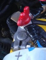
This is the marine terminal I bought ...
Shoreline Marine Battery Marine Terminal Kit ($7)
Amazon.com: Shoreline Marine Battery Marine Terminal Kit (Red/Black): Sports & Outdoors
It fit without issue.
As for the cable length - you may have to pull slightly. Mine was tight but I had just barely enough room to fit it on the terminals.
2)
I tried to replicate putting cut up pieces of rosin solder in the metal battery lug in a C-clamp and putting a torch on it as BFAD did. The solder melts into hardness with the mini-torch instantly, so when you put the cable in, you are just pushing against hardened solder. You can't crimp anything at that point.
This is what I did .....
Take clean exposed 4G wire and 4G metal end piece, make sure it fits onto your battery terminal, meaning if it needs to be 5/8 (?) then make sure it fits. I don't know what your terminal bolt will be.
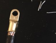
Take the wire, twist it, put it in the end piece, now shove in a few pieces of solder. I could only fit a few. THEN crimp so it stays in place. Then heat on the stove just long enough for the solder to melt. Now you have an end piece that is crimped and soldered.
Here is how I did it. Sorry I didn't post more details.
(Direct Link ---> post1349528)
http://www.toyota-4runner.org/3rd-g...-build-maintenance-thread-20.html#post1356923
Pictured below is pre-crimp. :bluejump:
Attachments
Last edited:

busmup808
New member
Here are the battery posts that I bought from Napa they are military grade. Negative post us on the battery and the positive is not yet, due to me not finishing the POSITIVE wires upgrade with 120amp.
NOTE: Stud for wires are facing sideways, compared to facing upwards.
NEGATIVE

POSITIVE

NOTE: Stud for wires are facing sideways, compared to facing upwards.
NEGATIVE
POSITIVE
Similar threads

- Replies
- 2
- Views
- 2K


- Replies
- 1
- Views
- 3K

- Replies
- 1
- Views
- 929


