Relay Problem?

Jtwo

New member
Hello,

I usually don't post much because I use the "search" function but I'm in a bind and don't feel like combing thru the numerous threads.

Ok-

Installed a LED light bar + rear LED's, ran the power from the LED's to the engine and ran the grounds from the LED's to the GOBI bolt (where it bolts to the roof) see [MENTION=65614]Antman[/MENTION]s post.

Installed the Bussmann relay box, had three bundles of cable: one to the switches, one on the fused relay, one that is not fused and is constant hot.

Running AOB switches that have 4 wires, one hot, one ground, one for illumination, one for 12v keyed supply.

So I wired up the switches hot to hot on switch cable coming from the bussmann relay box, grounded the switch to good ground. Didn't wire in the other two because I need to figure out a good source for illumination to the switches.

Wired the LED's to the "Relayed" cables on the Bussmann. Ground the circuit using [MENTION=65614]Antman[/MENTION]s idea.

I am not getting anything, nada, nothing at all to the switches but when I hook either LED to the constant 12v source coming out of the Bussmann I can get the LEDS to power on.

I know I have good grounds as I have ohmed the circuit, only time I get 12v is going to the constant "HOT" from the Bussmann.

What am I doing wrong???
 
Register to hide this ad
I'm not sure if I read the post correctly, but it sounds as though you need something to trigger the relay coil to click on. It sounds like you have constant hot wired in, but since there isn't anything to trigger the relay, the 12v is just sitting at the relay and not going through to the leds.
 
Agreed with above, you have to have 3 wires connected on the AOB switches, power, ground, and the other wire that isn't just for illumination (technical I know). Blue, black, and red, I believe, the green is the illumination wire for the switch (when not activated) and is the only optional one in the mix. Now how to fix that is well above my electrical knowledge sorry... and those wire colors are from a distant memory, blue and green could be backwards

I bet [MENTION=81322]barryhiram[/MENTION] can explain this from the perspective of someone that actually knows what they are talking about...
 
Last edited:
Hi Jtwo,

I didn't get every part of your problem description, but there are four things that are needed to make it work properly; follow those rules and you've got it.

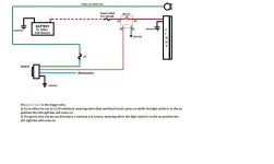
On your switch you have four wires: (1) Power (input) to the switch, (2) Power (output) to the relay coil (trigger), (3) Ground wire to the switch; serves only for the 'On-Off indicator led'/'Instru backlighting' and (4) Illumination circuit from the courtesy/instrument cluster (optional).

You can run all of your ground wires together. Run your Power (input) wires to the Bussman distribution sub-panel; one 20A fuse for all the switches should just be fine (Trigger: fractional current consumption). Each AOB switch has an output wire that goes to it's perspective relay coil (to be run separately). And your 'Illumination circuit': Tap into one of the other (oem) neighboring dash switch illumin wires and feed ALL of your new switches from that one tap; Green is HOT, Gray is GND.

That's it! Double check you wiring and see which one of those connections were missed. Rgds!
 
Last edited:
I suggest you recheck all your power and ground connections from the beginning and later through your relay connections. Zero your meter on the ohms scale. If you don't have this function record the value of your leads and then subtract that value from any other reading.

I would then measure all my ground points to chassis ground. If your Gobi rack isn't properly grounded and you connect to it as a ground point, your circuit won't function even though you measure good from your circuit test point to the rack. You should not measure more than 1 or 2 ohms on any ground connection. If you are getting a higher number then clean all connections and retest.

Once you have good power and ground numbers, you can then add your circuit connections in (in stages if possible) and continue your checks.
 
It's was what you, jhalko, and rigtec said about the switch not triggering the relay.

I tapped into the cigarette lighter circuit and that solved the problem.

Thanks for helping me out.
 
Hey [MENTION=81322]barryhiram[/MENTION],

...and where were you when we needed you on this thread... hahaha!

...So nice to learn that you stopped by :wave:
 
Late to the party again.......lol

I bet [MENTION=81322]barryhiram[/MENTION] can explain this from the perspective of someone that actually knows what they are talking about...

Thank you for the kind words :thumb3:

You guys nailed it, great job [MENTION=91899]Jhalko[/MENTION], [MENTION=3054]Lexusbstrdchild[/MENTION], [MENTION=83083]rigtec[/MENTION]
 
Hey [MENTION=81322]barryhiram[/MENTION],

...and where were you when we needed you on this thread... hahaha!

...So nice to learn that you stopped by :wave:

Sorry man, been on the road this past week for work. Finally was able to get a return flight from Norfolk, VA that was on time for once.

:moon: :fish:
 
Last edited:
Installed the Bussmann relay box, had three bundles of cable: one to the switches, one on the fused relay, one that is not fused and is constant hot.

Glad the guys got you squared away, great group here!

Any chance you could upload Bussmann's wiring schematic?
 
Just thought I would drop this here!
 

Attachments

  • Light circuit .JPG
    Light circuit .JPG
    92.1 KB · Views: 190

Members online

Forum statistics

Threads
278,305
Messages
3,554,041
Members
248,016
Latest member
Advally Service

Trending content

Back
Top