Wire Connector Advice

rdswriter

New member
Wire Connector Advice Needed

I'm finally going to be wiring up my first additional AOB switch in my T4R next week, but have plans for additional switches in the future. My questions relate to tapping into the Wiper Warmer switch for dimming/grounding.

1) Obviously I can tap one AOB switch into the Wiper Warmer green & grey wires for illumination & dimming, but how many additional switches could I leverage off these same OEM wires?

2) I'd like to make it as easy as possible to tap into the OEM Wiper Warmer green & grey wires, so I'm considering using something like the following connector - WAGO. Has anyone used these before on their vehicles?

3) Is there some other "one-to-many" wire connector I should consider for AOB switches (for illumination/dimming)?
 
Register to hide this ad
You can tap into the illumination wires under the shift console. If you do not have heated seats there are two sets of the illumination wires you can use. They are for the factory heated seat switches.


2011 4Runner Trail with KDSS
1992 Land Cruiser
 
"...Is there some other "one-to-many" wire connector I should consider for AOB switches (for illumination/dimming)?"

Hi rdswriter,

There are 1,000,000.00 ways to connect the wires together, but I like to keep things real simple. So I'll usually just trim back the mesh a bit; giving myself enough wire and enough room to work. Then I'll cut the Green POS (+) and the Gray NEG (-) wires, strip them back, leaving about a 1/2 an inch of exposed copper.

I'll twist the green to the green and the gray to the gray together, and those I'll push into 'one end' of a RED 16-18ga butt connector and crimp them; giving them a little tug and making sure that they won't come apart after I put it all back together.


Then I'll cut two pieces of 14ga wire around 10 inches long and I'll secure them into the other end of the red butt connector; I may need to trim a few strands of copper off of the end to fit them in. The reason that I chose to leave them as long as I do is so I can use them for ALL of the other A.O.B. switches that will be used in the dash (in the future), and I don't really like disturbing such short, small gauge factory wiring in such a confined space in the dash! Now on my new aob switch that I'll be installing I'll use a Male & Female Spade terminal for ease of install and removal.


And, when I install any additional switches I'll make-up a few Y spade connectors so... no more splicing inside the dash; just 'plug-n-play'! NOTE: If you do decide to use male & Female stay-conn spades, it's a very good idea to wrap the stay-conns with electrical tape to help keep them from coming loose from vibration and also to prevent any exposed strands of wire or metal parts of the connectors from making contact with any potential ground that may be near-bye! Hope you'll find something in this post helpful,

rig, 'Best to you'!
 
Hi rdswriter,

There are 1,000,000.00 ways to connect the wires together, but I like to keep things real simple. So I'll usually just trim back the mesh a bit; giving myself enough wire and enough room to work. Then I'll cut the Green POS (+) and the Gray NEG (-) wires, strip them back, leaving about a 1/2 an inch of exposed copper.

I'll twist the green to the green and the gray to the gray together, and those I'll push into 'one end' of a RED 16-18ga butt connector and crimp them; giving them a little tug and making sure that they won't come apart after I put it all back together.


Then I'll cut two pieces of 14ga wire around 10 inches long and I'll secure them into the other end of the red butt connector; I may need to trim a few strands of copper off of the end to fit them in. The reason that I chose to leave them as long as I do is so I can use them for ALL of the other A.O.B. switches that will be used in the dash (in the future), and I don't really like disturbing such short, small gauge factory wiring in such a confined space in the dash! Now on my new aob switch that I'll be installing I'll use a Male & Female Spade terminal for ease of install and removal.


And, when I install any additional switches I'll make-up a few Y spade connectors so... no more splicing inside the dash; just 'plug-n-play'! NOTE: If you do decide to use male & Female stay-conn spades, it's a very good idea to wrap the stay-conns with electrical tape to help keep them from coming loose from vibration and also to prevent any exposed strands of wire or metal parts of the connectors from making contact with any potential ground that may be near-bye! Hope you'll find something in this post helpful,

rig, 'Best to you'!

Great idea! Doing this the next time I'm in the dash doing electrical!
:tea:
 
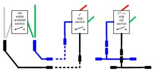
Rigtec... if I understand what you're saying, the wiring schematic would look similar to image below. Initially one would simply wire the 1st switch using a male and female spade terminals. As switches would be added, a Y spade connector could be used to connect the first switch and provide for an additional spade terminal. Each additional switch would effectively need 2 additional Y connectors, Right?

In short, all of the future AOB switches would be in parallel to the other switches. My only concern is the effect of the additive amperage. AOB indicates that their switches are 12V/3A, so adding multiple switches in parallel would add 3A for each switch on the circuit.
Would these additional switches overload the original green & grey wires and or the fuse that that the OEM circuit is on?
Or, is the 12V/3A rating from AOB a maximum... and actual switch amperage is negligible to affect the circuit?

I'm relative new to 12V wiring (as opposed to home 120V AC wiring). Thanks for any additional advice.
 

Attachments

  • Switch Daisy Chain.JPG
    Switch Daisy Chain.JPG
    26.1 KB · Views: 595
Last edited:
In short, all of the future AOB switches would be in parallel to the other switches. My only concern is the effect of the additive amperage. AOB indicates that their switches are 12V/3A, so adding multiple switches in parallel would add 3A for each switch on the circuit.
That 3 amp rating is almost certainly the rating for the amount of current they can switch, not the draw of the backlight. An LED at 36 watts would be incredibly bright, and require some fancy cooling not to burn out in a matter of seconds.
 
Last edited:
"...My only concern is the effect of the additive amperage. AOB indicates that their switches are 12V/3A, so adding multiple switches in parallel would add 3A for each switch on the circuit..."

"...I'm relative new to having to 12V wiring (as opposed to home AC wiring). Thanks for any additional advice."

Hi rds,

You understood my post 100%, apparently your electrical theory is neatly secured under your belt (regardless of voltage rating) as it should be! Now as far as the 3A nomenclature rating on the AOB switch (as [MENTION=78273]Jeremy556[/MENTION] has advised), this is referring only to the maximum amperage load that the switch itself can safely carry, but most of us will use a relay to carry the actual load e.g., LED light bars, Fridge, winch...etc! The switch will be used to 'trigger' (open and close) the relay; which will commonly handle anywhere from 15A all the way up to 50A and will generally be connected directly to the battery (via supplied harness) as per manufacturer's instructions. A load higher then that will usually require a designated contactor to shoulder a load that large e.g., 100A, 200A 300A...!

And as far as the tiny LED behind the 'Etched face' of the switch, you need not worry about the courtesy circuit becoming overloaded just because you've added a few of switches to your dash; you'll run out of unused Toyota 'Blank-offs' in the dash before you'll pose any electrical hazard to that circuit as these parking light on indicators draw only milli-Amps (mA) when they're on! I'm hoping that my explanation to your questions has helped you to develop a mental picture of how all things are connected... I'm aware that auto electrical systems can be quite intimidating until you have become somewhat acquainted with the many protocols!

'Best to you'!
 
Thank you Rigtec and Cymon for all the information throughout t4r.org regarding wiring.

What I've quickly learned from reading a multitude of threads is home vs. automotive is very different. Wiring color coding changes, lack of consistency across aftermarket harnesses, grounding issues easily occur, ports 1,2,3,4,5... mean something different for every harness connector and the possibility of cross-wiring and damaging an electrical device is a real possibility due to the inherent nature of the vehicle systems being pre-wired.

For me... I've rewired a couple homes and AC wiring is incredibly simple compared to automotive. This is why I really like the concept of never tapping into existing wires for new equipment on a vehicle. All of my new circuits will trace back to the battery. That being said... the exception that must be made is the illumination/dimming of switches.
 
Thank you Rigtec and Cymon for all the information throughout t4r.org regarding wiring.

What I've quickly learned from reading a multitude of threads is home vs. automotive is very different. Wiring color coding changes, lack of consistency across aftermarket harnesses, grounding issues easily occur, ports 1,2,3,4,5... mean something different for every harness connector and the possibility of cross-wiring and damaging an electrical device is a real possibility due to the inherent nature of the vehicle systems being pre-wired.

For me... I've rewired a couple homes and AC wiring is incredibly simple compared to automotive. This is why I really like the concept of never tapping into existing wires for new equipment on a vehicle. All of my new circuits will trace back to the battery for the hot feed. That being said... the exception that must be made is the illumination/dimming of switches.
 

Members online

Forum statistics

Threads
278,306
Messages
3,554,045
Members
248,016
Latest member
Advally Service

Trending content

Back
Top