400W Inverter Mod?

keithsnell

New member
Has anyone done a mod on the 5th gen similar to the Tacoma mod at this link to deactivate the 100w inverter limit when driving (enable 400W all the time)?

Here's the link: 110v factory inverter - Always 400w - Toyota Nation Forum : Toyota Car and Truck Forums

Any of you "mod masters" willing to give this a try?

EDIT: The wiring diagram referenced in the link above is for an earlier model Tacoma and the wire colors are different. I do intend to do this mod soon, and will attach updated instructions/wiring diagrams after I have successfully completed the mod. (I intend to implement the mod with a center console mounted switch so that I can easily switch between "factory" inverter wiring/behavior and "forced" 400W operation.)
 
Last edited:
Register to hide this ad
Looks easy enough. I might try it this week

Thanks. I'd be very interested in hearing your results if you give it a try.

I'm curious WHY toyota thought it necessary to limit the inverter wattage while driving, so if anyone has any insight I'd love to hear the reason. It seems like a fairly complex design in order to automatically reduce the inverter power while driving, so they must have had some rationale. I wonder if there is some sort of NHTSA safety requirement that they were forced to comply with??
 
Probably has to do with fuel consumption. Alternators at full generation are not easy to turn

Good point. I did notice a difference in fuel consumption in the '96 4Runner with my dual battery setup when the alternator was recharging a depleted auxiliary battery.
 
that doesnt bother me as the location of the outlet in the console.... I need to tear it apart and look inot relocating it to the back of the console for the kids to utilize
 
Inverter indicator light anomaly or normal?

I'm getting ready to do the 400W Inverter Mod, but first have a question on the inverter power indicator lights that I'm hoping someone can verify for me.

The manual indicates that both the 400W and 100W lights will be on when the switch is pressed and the vehicle is in P or N, and that only the 100W light will be on when the shift lever is in any position other than P or N (or the vehicle is moving). Strangely enough, my indicator light switches from both on (when in park) to only the 400W light illuminated when the shift lever is moved to another position. This is different than what is in the manual. This makes me wonder if my switch is wired incorrectly, (or maybe the slim possibility that the previous owner already modified the inverter wiring??)

Can somebody please check your inverter indicator light and see which one of the lights is illuminated when the shift lever is in a position other than P or N? (My vehicle is a 2010 TE)

Thanks!

EDIT: To answer my own question. My switch is wired in accordance with the official Toyota 120V outlet wiring diagram. Oddly enough, this wiring diagram indicates that only the 400W light will be illuminated when the inverter is in 100W mode. This conflicts with the manual, which indicates that only the 100W indicator light will be illuminated when the inverter is operating in 100W mode. It would be interesting to see if Toyota caught this error and corrected it in later (post 2010 models).
 
Last edited:
The wiring diagram referenced in the link above is for an earlier model Tacoma and the wire colors are different. I do intend to do this mod soon, and will attach updated instructions/wiring diagrams after I have successfully completed the mod. (I intend to implement the mod with a center console mounted switch so that I can easily switch between "factory" inverter wiring/behavior and "forced" 400W operation.)
 
Probably has to do with fuel consumption. Alternators at full generation are not easy to turn

Maybe a hair of extra load, but as far as I understand, the 12VDC load pulled by the inverter will be proportional to the load you are putting on the inverter (on the 120VAC side). So, if you are only pulling like 50 watts of 120VAC on the inverter, I could not see the load put on the 12VDC electrical system being any different in 100Watt mode or 400Watt mode (save for a few watts).

I've always been a bit perplexed by the elimination of the 400 Watt mode if you are driving, because you are generally getting more output from the alternator with the engine running above idle (or than with the engine off ;) ).

I tested my inverter once when I bought the truck (read the manual cover-to-cover within 4 hours of owning my new baby, and tested it at that time), but haven't used it since - so I'm not terribly concerned with executing this mod (or believe me: I would have it figured out a long time ago!) :wave:

:cool:
 
So I finally cracked in to the rear inverter area (passenger wheel well) and took a look at the wiring. Is there anyone who knows what the equivalent wire colors would be for us?

thanks
 
Know that you might be hacking into a BCM area.

Consider adding another inverter. The 400W'ers can be had cheap. Plug into 12V outlet. Done.

BCM problems down the road on modded rigs don't seem to be getting much love from Dealers.

If you're out of warranty then go for it. You could always "hardwire" the whole truck one day.
 
Hi Spencertron,

I have to admit that I never actually got around to doing this mod. The most useful information I found was from a (now deleted) post on the Tacomaworld forum. Here's the pertinent text from that post:

Connect the following to the inverter (I used terminal names from wiring diagram to avoid confusion)

+B - from 100A fuse to battery
CCCL - Leave disconnected and capped
NSW - Tie to ground
Out - Tie to the ECM recommended connection (not sure what this is used for exactly)
SPD - Leave disconnected and capped
PGND - Tie to ground
AC1 and AC2 - AC Line and return output from the inverter. Wire to whatever your heart desires!
P/T - Wire to load end of switch
400W - 400W LED indication on switch (optional to hookup IMO)
REDR - 100W LED indication on switch (also optional)


Edit: The combination meter is a computer which measures the pulses of the wheels to cacluate vehicle speed. It has various outputs at different speed to satisfy permissives and interlocks for certain equipment.​

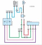
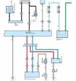
I've attached the electrical diagrams for the 120V inverter.

Hope this helps,
Keith

View attachment Power Outlet (120V) (2010 4Runner) .pdf
 

Attachments

Hi Spencertron,

I have to admit that I never actually got around to doing this mod. The most useful information I found was from a (now deleted) post on the Tacomaworld forum. Here's the pertinent text from that post:

Connect the following to the inverter (I used terminal names from wiring diagram to avoid confusion)

+B - from 100A fuse to battery
CCCL - Leave disconnected and capped
NSW - Tie to ground
Out - Tie to the ECM recommended connection (not sure what this is used for exactly)
SPD - Leave disconnected and capped
PGND - Tie to ground
AC1 and AC2 - AC Line and return output from the inverter. Wire to whatever your heart desires!
P/T - Wire to load end of switch
400W - 400W LED indication on switch (optional to hookup IMO)
REDR - 100W LED indication on switch (also optional)


Edit: The combination meter is a computer which measures the pulses of the wheels to cacluate vehicle speed. It has various outputs at different speed to satisfy permissives and interlocks for certain equipment.​

I've attached the electrical diagrams for the 120V inverter.

Hope this helps,
Keith

View attachment 143185

Thanks for your help! I think i'll have to re-think this mod because I pretty much have no idea what i'm looking at here haha. Are the names of those wires the same as on the diagram? I'm not seeing them anywhere.
 
Are the names of those wires the same as on the diagram?

Yes and no. The author of that post was referencing an older version of the inverter diagram for the Tacoma, so some of the connections are different. In addition, he was describing how to install the factory inverter "from scratch."

I've cross correlated the wiring diagrams, and I believe the only two wires you need to worry about are the NSW wire (black wire leaving the inverter) and the SPD wire (light blue wire leaving the inverter).

The NSW wire connects to the Park/Neutral position switch. This switch provides a ground when the transmission is in the park or neutral postion, and enables the 400W setting on the inverter. Grounding the NSW wire should enable the 400W funcion full time. (Cap the end coming from the park sensor, and ground the end going to the inverter.)

The SPD wire connects to the speed sensor. The author of the post on Tacoma World said to "leave disconnected and capped", so you would just need to snip and cap this wire.

Before cutting any wires, you might want to use a circuit tester to confirm the functions of the wires you intend to cut (i.e., verify the correct wire "switches to ground" when the shifter is in the Park or Neutral position.)

Hope this helps.

Keith
 
Yes and no. The author of that post was referencing an older version of the inverter diagram for the Tacoma, so some of the connections are different. In addition, he was describing how to install the factory inverter "from scratch."

I've cross correlated the wiring diagrams, and I believe the only two wires you need to worry about are the NSW wire (black wire leaving the inverter) and the SPD wire (light blue wire leaving the inverter).

The NSW wire connects to the Park/Neutral position switch. This switch provides a ground when the transmission is in the park or neutral postion, and enables the 400W setting on the inverter. Grounding the NSW wire should enable the 400W funcion full time. (Cap the end coming from the park sensor, and ground the end going to the inverter.)

The SPD wire connects to the speed sensor. The author of the post on Tacoma World said to "leave disconnected and capped", so you would just need to snip and cap this wire.

Before cutting any wires, you might want to use a circuit tester to confirm the functions of the wires you intend to cut (i.e., verify the correct wire "switches to ground" when the shifter is in the Park or Neutral position.)

Hope this helps.

Keith

thanks again for your help. would i have to do this to both inverters in order to keep things from freaking out (really i think it would only effect the switch on the dash but that doesn't matter much to me). thanks again.
 
would i have to do this to both inverters in order to keep things from freaking out

There is only one inverter. It switches "modes" from 400W to 100W depending on whether the vehicle is moving or not. By grounding the
NSW wire you are fooling the inverter controller into thinking the vehicle is in park or neutral (and therefore not moving), and by snipping the wire to the speed sensor you are preventing that sensor from sending a signal to the inverter contoller telling it to drop down to 100W (at any speed other than zero).

I'm guessing that these two redundant methods of indicating that the vehicle is moving are probably there in order to have a method to determine whether the vehicle was in motion for both an automatic and manual transmission (thus the link to the speed sensor).

I don't know why they chose to implement the inverter in this manner, but I'm guessing the engineers were probably told to stay within a certain "power budget" when the vehicle was moving, probably in order to ensure that all the other vehicle systems would have enough power to operate properly.
 
There is only one inverter. It switches "modes" from 400W to 100W depending on whether the vehicle is moving or not. By grounding the
NSW wire you are fooling the inverter controller into thinking the vehicle is in park or neutral (and therefore not moving), and by snipping the wire to the speed sensor you are preventing that sensor from sending a signal to the inverter contoller telling it to drop down to 100W (at any speed other than zero).

I'm guessing that these two redundant methods of indicating that the vehicle is moving are probably there in order to have a method to determine whether the vehicle was in motion for both an automatic and manual transmission (thus the link to the speed sensor).

I don't know why they chose to implement the inverter in this manner, but I'm guessing the engineers were probably told to stay within a certain "power budget" when the vehicle was moving, probably in order to ensure that all the other vehicle systems would have enough power to operate properly.


Aaaah so there are just two OUTLETS. I thought maybe there was a second one under the center console. Well thank you again for all your help. I'm going to try this out! I'll either have a happy report and a full time 400w inverter or I'll be joining a beater corolla forum cuz I blew up my 4runner :)

Thanks again,
spencer
 
Here's the wiring diagrams from 2010 but should be the same for all 5ths for the inverter however I'm with [MENTION=86216]Biggcrisp[/MENTION] on this one. Much safer and ultimately a bigger/better inverter to wire your own aftermarket one on it's own separate circuit without the potential Toyota CANbus and BCM troubles.Big truck and plenty of places to put one.

We've seen more then once the headaches related to hacking into the factory electrical. Dirty inverters ,like the factory ones in the 5ths most likely are, are not that expensive.
 

Attachments

  • inverter2.jpg
    inverter2.jpg
    99.4 KB · Views: 8,859
  • inverter3.jpg
    inverter3.jpg
    100.6 KB · Views: 4,779
Last edited:

Members online

Forum statistics

Threads
278,307
Messages
3,554,056
Members
248,016
Latest member
Advally Service

Trending content

Back
Top