98' 4runner timing issue

Ooo, that is rough. You plugs could be toast with soot from rough idling. What are your LTFT and STFT readings?

I don't have those readings but I believe I can get them with the Scangauge ii if I can find the xgauge commands somewhere online.

Have you tried troubleshooting with a vacuum gauge? It can be a great tool in seeing what the engine is doing while running rough. Could help with the direction onto where to look at.
The parts stores used to rent these but, I can't find the tool number now.

Edit: You can't get the ltft/stft readings if the engine hasn't fully warmed up and is in open loop.

I have not tried using a vacuum gauge. It seems that I could get some useful info from performing that test. I will see if I can find a part store with a loaner or purchase one.

Thanks for the to tip
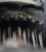
 
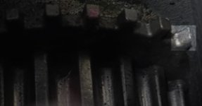
I've turned the engine over and over looking at those teeth until I felt crazy at one point of trying to troubleshoot this... It's distortion in the picture if anything

I'm no photo expert, but this doesn't seem to be distortion to me.

In my experience even 1 tooth of an exciter ring or trigger wheel can devastate a system. ABS systems or ignition systems
 

Attachments

  • timing.jpg
    timing.jpg
    77.5 KB · Views: 326
OP already check it on post 27, and reported it as pic distortion.

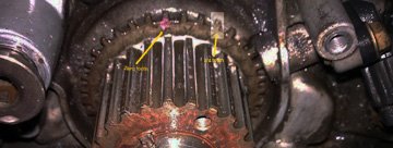
Zero tooth is the one with the red paint.
The 3rd tooth to the right of zero tooth IS physically still there but, it does seems like it is missing a angular chunk on the TOP of it.

From the top of the engine looking down to the crank sprocket could look fine as it seems like the same shape with the ones before and after it.

It could be possible to see that missing chunk by looking at it from the front of the engine straight on as it will be a smuge shorter (than the ones to the left and right of it) because of that missing chunk.

I know the engine is all buttoned up. Would it be possible to snap another pic on the 3rd tooth from the front straight on? Need to confirm showing the height of it?

If that tooth doesn't look symmetrical (height wise) like the 2nd tooth or the 4th tooth beside it, your engine will not run right and could explain the rhythmic miss and misfiring though the exhaust. That shorter tooth is cutting the signal to the coils for a fraction of a second and turning it back on.

That missing tooth will cut the signal to the ecm when is sees that shorter 3rd tooth, and turn it back on when is sees the 4th tooth, 5th tooth, etc and so on.
 

Attachments

  • tooth.jpg
    tooth.jpg
    35.4 KB · Views: 315
  • tooth2.1.jpg
    tooth2.1.jpg
    51.3 KB · Views: 340
So I grabbed a vacuum gauge and here are my results.

From cold start.
Shared album - Aaron Soniat - Google Photos

Operating temperature
Shared album - Aaron Soniat - Google Photos

I guess I'm going to order a new sprocket and tear it back down... Like one of you said, that tooth may have looked fine from my point of view when I double checked. I didn't take it off completely, the last time I confirmed the hard marks. Would this be the recommendation of the experienced?
 
Last edited:
I have to get the part number for the crankshaft bolt again and order one of those also.

Any suggestions on where to order these from that will arrive quickly?
 
I have to get the part number for the crankshaft bolt again and order one of those also.

Any suggestions on where to order these from that will arrive quickly?

Might have it available at a local dealership(I’d try to call ahead of time to make sure), might even be cheaper cause you won’t have to pay 15$ for shipping a 7$ part lol.
 
Ok. Vacuum reading is steady but low.
I was leaning towards you having defective heads from the re builder like a sticking valve guide, not fully seating valve or a bad cam, etc. Anything going on with the valves or valve guides would've came out on the vacuum reading and compression test. And you had a steady reading which is good.

Your thermo readings on the exhaust ports were nice and almost even on all 6 cylinders. Indicating a steady flame on all 6 cylinders.

Your compression test was good, somewhat even. No excessive high or low cylinders.

Great vacuum reading would be in the 18-20 range. Your is a steady low 14-13.
So if you go back to the chart on the vacuum gauge pages, it's has defective ignition components as a probable cause.

That chipped tooth could affect the signals going to the ignition coils cause of that low vacuum reading.

I really feel you are close into solving this.:thumb3:

Crank bolt 11/95-9/98: 90105-16031
9/98-...: 90119-16006

Sprocket: 13521-62031
 
Ok. Vacuum reading is steady but low.
I was leaning towards you having defective heads from the re builder like a sticking valve guide, not fully seating valve or a bad cam, etc. Anything going on with the valves or valve guides would've came out on the vacuum reading and compression test. And you had a steady reading which is good.

Your thermo readings on the exhaust ports were nice and almost even on all 6 cylinders. Indicating a steady flame on all 6 cylinders.

Your compression test was good, somewhat even. No excessive high or low cylinders.

Great vacuum reading would be in the 18-20 range. Your is a steady low 14-13.
So if you go back to the chart on the vacuum gauge pages, it's has defective ignition components as a probable cause.

That chipped tooth could affect the signals going to the ignition coils cause of that low vacuum reading.

I really feel you are close into solving this.:thumb3:

Crank bolt 11/95-9/98: 90105-16031
9/98-...: 90119-16006

Sprocket: 13521-62031


If it isn't the sprocket where would I go next? I'm 99.9% sure, after thinking about how much I inspected the sprocket , that the teeth are good BUT I am human. I may have torn it down 4 times already but I want to be humble in taking advice from you guys so I'm still planning to tear it down tomorrow if that's the suggestion but have a feeling I'm going to be disappointed. I'm not trying to jump ahead, just asking before I proceed.
Edit: I came across this chart while searching a few things. With my readings this narrows it down to late valve timing. Not sure if that makes any difference in which direction to take.
ENGINE VACUUM TROUBLESHOOTING | Classic Car Restoration Club
 
Last edited:
Not trying to be sarcastic.
I have followed you tearing down the timing set more times than you have like trying to execute troubleshooting advice tips this site have suggested. Probably by now you can tear the timing set down, and put it back together then, have the engine running, with your eyes closed and in a great speedy time some of us wish we could do!

You don't have to follow what members here suggest you should do. Some (like me) post what may have worked for me in the past or, post/share what I would do if they were in my shoes.
You are your own person and able to sense what you should do next in your best interest based on what you have seen and experienced.
Like I said, not trying to put anyone down or, be sarcastic. Just trying to help a fellow member out.
Wishing you the best and really rooting for you to have an operational 4r soon!
 
Not trying to be sarcastic.
I have followed you tearing down the timing set more times than you have like trying to execute troubleshooting advice tips this site have suggested. Probably by now you can tear the timing set down, and put it back together then, have the engine running, with your eyes closed and in a great speedy time some of us wish we could do!

You don't have to follow what members here suggest you should do. Some (like me) post what may have worked for me in the past or, post/share what I would do if they were in my shoes.
You are your own person and able to sense what you should do next in your best interest based on what you have seen and experienced.
Like I said, not trying to put anyone down or, be sarcastic. Just trying to help a fellow member out.
Wishing you the best and really rooting for you to have an operational 4r soon!
You're right about nearly being able to tear down and reassemble with my eyes closed.

My question in my last post was not meant to challenge anyone's suggestion. I respect the time that you and others have spent to give advice and only trying to give information that I am coming across. I'm not trying to get around executing anyone's suggestions either. Time is valuable and the last thing that I want is to waste anyone's. I'm only asking questions to learn. Your knowledge on the situation is greater than mine and I have no doubt in anything suggested. I'm really appreciative for all of you in this community.

I apologize if I gave any other impression.
 
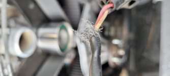
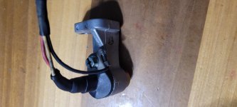
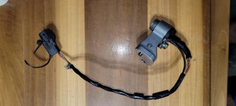
I'm taking everything off the front of the engine and decided to unwrap any wires that I had rewrapped and taped. This is my camshaft sensor and the end of the black wire that mounts to the body of the sensor. I wouldn't think that it's suppose to be this way.
 

Attachments

  • 20210531_172229.jpg
    20210531_172229.jpg
    137 KB · Views: 321
I can confirm that your sprocket is flawless. There is a slight chance that the paint on the end of the tooth could interfere with the crank position sensor, but I really doubt it is the case.

Normally when all cylinders run within a pretty tight temperature tolerance it is likely that the base electricals for the ignition (plugs, plug wires, coil banks) are all completely fine. It also suggests that none of the injectors are firing completely out of whack.

There is still potential with it immediately dying under load (shifting into drive) that it could be something as simple as your fuel pump or fuel filter. Have you done a fuel flow test and check the fuel pressure as steps in this process?

If fuel checks out, I would go on to checking for intake manifold/vacuum leaks.

If everything there checks out, it is likely an issue with sensors, the wiring harness, or even the ECU.
 
I'm taking everything off the front of the engine and decided to unwrap any wires that I had rewrapped and taped. This is my camshaft sensor and the end of the black wire that mounts to the body of the sensor. I wouldn't think that it's suppose to be this way.

Oh geez louise that's a grounded sensor!! 100% sure that's your problem. Remember what I was saying it was acting like you had a bad sensor? Well you just found it. Is that rats nest of a wire on the connecter side or the wiring harness side? Can't really tell. Obviously, that entire section needs to be cut out and replaced. Junkyard camshaft sensors work fine. I may even have one in my shed if you want it.

And you are saying there's other wires that are wrapped like this???
 
Last edited:
Oh geez louise that's a grounded sensor!! 100% sure that's your problem. Remember what I was saying it was acting like you had a bad sensor? Well you just found it. Is that rats nest of a wire on the connecter side or the wiring harness side? Can't really tell. Obviously, that entire section needs to be cut out and replaced. Junkyard camshaft sensors work fine. I may even have one in my shed if you want it.

And you are saying there's other wires that are wrapped like this???

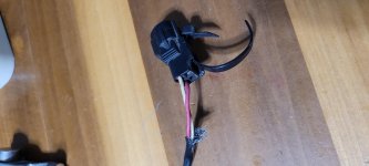
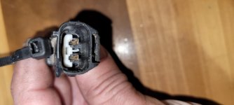
It is on the connector side but the connector has only 2 contacts so I don't believe it's suppose to be wired to the connector. I reloomed everything while doing this project is what I meant. There are no other wires wrapped up that are in the same condition as this one.
 

Attachments

  • 20210601_045516.jpg
    20210601_045516.jpg
    136 KB · Views: 312
  • 20210601_045533.jpg
    20210601_045533.jpg
    139 KB · Views: 325
  • 20210601_045550.jpg
    20210601_045550.jpg
    122.9 KB · Views: 324
  • 20210601_050047.jpg
    20210601_050047.jpg
    137.5 KB · Views: 315
I'm taking everything off the front of the engine and decided to unwrap any wires that I had rewrapped and taped. This is my camshaft sensor and the end of the black wire that mounts to the body of the sensor. I wouldn't think that it's suppose to be this way.
I think that's just shielding in the wiring harness. My electrical wiring diagram lists the camshaft and crankshaft sensor circuits as shielded, and it doesn't look like it's a frayed wire or that there is a spot in the connector for it. The one end of it looks to be grounded to the connector body as well.
 
I think that's just shielding in the wiring harness. My electrical wiring diagram lists the camshaft and crankshaft sensor circuits as shielded, and it doesn't look like it's a frayed wire or that there is a spot in the connector for it. The one end of it looks to be grounded to the connector body as well.
I believe that is correct. A new sensor has 3 wires in the sensor side but only 2 go through the wire sleeve and into the connector.

Sent from my SM-G781U using Tapatalk
 
I believe that is correct. A new sensor has 3 wires in the sensor side but only 2 go through the wire sleeve and into the connector.

Sent from my SM-G781U using Tapatalk

A 30 min trip to the pick and pull and you'll know for sure if that's the problem or not. Shouldn't cost more than $15.
 
The last wiring harness I got with a donor motor from a later year 5VZ had 3 prongs on the harness and sensor side. My 96 and 97 harnesses both had 2 prongs on the harness and the sensor side. I don't know exactly when the change happened, but that is what mine are like. It is probably just an additional ground and I doubt that section is messed up with just the loom separating.
 

Members online

No members online now.

Forum statistics

Threads
278,309
Messages
3,554,068
Members
248,016
Latest member
Advally Service

Trending content

Back
Top