A/C upgrade

GonOvr

New member
My brain is fried trying to figure this out.

As many of you know I have a V8 but I also have everything to run A/C except how to wire it to make it work. All I need to know is how to wire up the compressor so it comes on with the switch and cycles when its supposed to. Someone smarter than me, please tell me how to do this time now! By the way I am using a sanden style 508 compressor

P.S. If you refer me to the manual I will kill you. If any of you actually looked at the schematic you would see all the BS that is between the switch and compressor.

Have a super night!
 
Last edited:
Register to hide this ad
Would it be as simple as wiring a relay between the switch and compressor?

My buddy has an old toyo hardbody w/ a 350 in it, and he had the same problem, I remember he was missing a ground, and yes he needed a relay... sorry for the vague answer, this was years back.
 
If I run direct power to the clutch it will stay on and not cycle, correct?

My Grounds are good and grounds are easy. I need the compressor to cycle without me having to hit the button every 5-8 sec.

I may break down and pay someone to accomplish this. All these relays, pressure switches, and the Amplifier are F-ing with my goal.
 
With all the hot rodders out there you would think that someone has a pre-made wiring harness for your type of application. If you can find a pre-made wiring harness then I would be willing to bet that you can copy the design and make your own. Check out some of the hot rodder forums. There are tons of people who wire their own kits for their custom build rods.
 
A/C wiring schematic

1st page, center, bottom. A/C magnetic clutch. I need that black w/ white stripe wire to get 12v. Now do I have to charge the system in order to get 12v?

My understanding is that it should be 12v constant without a charge. When you fill it with refrigerant, the system cuts off the compressor intermittently (compressor cycle).

Again someone smarter than me tell me how to make that B/W go hot with the A/C switch on.

I have taken the hot rod approach but since i am integrating foreign and domestic nobody knows.

I am pretty good at wiring but i need a toyota wiring master's help with this one.
 
dont try to make sense of your set up make your own
your lucky you can just use a GM compressor youll have to rig your stock ac lines to fit the gm pump but as long as you can do that your stock heater controls should control the flow into the vehicle and your fan will control how much cold air can come in you wont get as good of climate control via the slider but you will get cold air.

http://www.senasys.com/shop/products-page/2511-34-heavy-duty/2511l036/
so with this switch i would go open by 45 and close by 35.
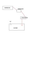
when the the condenser hits 45 degrees the circuit will open and turn the pump on then when it hits 35 degrees it will close the circuit turning the compressor off.
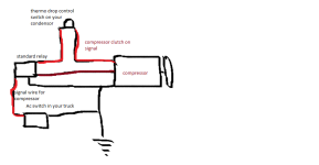
its crude but it will work without a bunch of headaches and its only like 20$ total to do this
 

Attachments

  • ac system.png
    ac system.png
    24.3 KB · Views: 739
Last edited:
dont try to make sense of your set up make your own
your lucky you can just use a GM compressor youll have to rig your stock ac lines to fit the gm pump but as long as you can do that your stock heater controls should control the flow into the vehicle and your fan will control how much cold air can come in you wont get as good of climate control via the slider but you will get cold air.

2511L036 |
so with this switch i would go open by 45 and close by 35.
when the the condenser hits 45 degrees the circuit will open and turn the pump on then when it hits 35 degrees it will close the circuit turning the compressor off.
its crude but it will work without a bunch of headaches and its only like 20$ total to do this

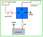
Hell yea! But I think I will put the thermo disc on the relay activating side. Instead of the the main line to the compressor. Not sure how many amps that clutch will spike when it engages.

I appreciate it bad! I was looking at it way too hard. Kick-Ass drawing by the way.
 
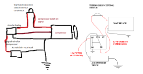
This is a first for me so I did some reading and tried to learn a little about this. Then I went off of BV's diagram and tried to understand his rough drawing. I basically came up with this. I used a standard 5 pin relay (as opposed to BV's 4-pin drawing). From what I understand on how a relay would work in this application and what the a/c compressor needs, this should be a dummy proof diagram of the install. Let me know if this seems way off and I'll modify or delete this post to prevent confusion. This is good info for motor swap guys so lets see if we can get as detailed as possible here.

BV's diagram on the left, mine on the right.
 

Attachments

  • ac%20system.png
    ac%20system.png
    30.8 KB · Views: 2,170
Last edited:
for future reference the only reason for the relay is to send power to the thermo drop switch only when you push the ac button in the truck. so if the ac isnt on your compressor will be in free turn mode
 
One thing though, sorry i looked at it about 5am.

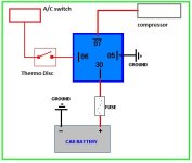
I have 1 wire on my compressor. It has a ground but going to itself. I assume still use 87. I dont think I want the the thermodisc cutting the power to the compressor but instead to the relay. It would be alot easier to cut power on the switched side of the relay. If you do it on the compressor side, you basically turn the thermodisc into the relay.

This is what I was thinking
AC4runner.jpg~original
 

Attachments

  • AC4runner.jpg
    AC4runner.jpg
    24.9 KB · Views: 618
Last edited:
however you go about it its still the most simple solution thermo drop switch and a relay 20$ haha the cheapest part of the swap was making the ac work go figure.
 

Attachments

  • AC4runner.jpg
    AC4runner.jpg
    24.9 KB · Views: 892
In that case, adding a relay would be pointless unless I'm missing something. Just run your fused power directly to your on/off switch.
 

Attachments

  • untitled.jpg
    untitled.jpg
    11.8 KB · Views: 577
In that case, adding a relay would be pointless unless I'm missing something. Just run your fused power directly to your on/off switch.

Simple yes, but too many amps get pulled through the switch. It would eventually melt the switch down.
 
thermo drop sensors delicate they need to control a signal only not a load.
you would have to have the sensor switch the relay that will ensure longevity and reliability
 
From my understanding, the only times when you need a relay is when you want to either reduce your wiring or have one switched power source run multiple things. In your case with the earlier schematics, it was to reduce your wiring to run constant power to your compressor and switched power to your thermo disconnect.

I have been trying to find a wiring diagram for a 3 wire a/c compressor to see exactly what wires go to what and what they require. Google is not very helpful in this case :(

But in your case you have a 1 wire compressor. That one wire just controls your mag clutch. You don't need a relay, that just complicates things and adds un-necessary wires to the mess.
 
Well that defeats the purpose of having a factory switch to use.

You should always use relays in high amp circumstances. That way the relay is doing the grunt of the work, the switch is just turning the relay on. Your wires will be a lot happier too.
 

Members online

No members online now.

Forum statistics

Threads
278,306
Messages
3,554,045
Members
248,016
Latest member
Advally Service

Trending content

Back
Top