aemravan's build thread - project TacoRunner

Not at all silly, I studied Devons FJ write up and the Marlin instructions for a couple days.

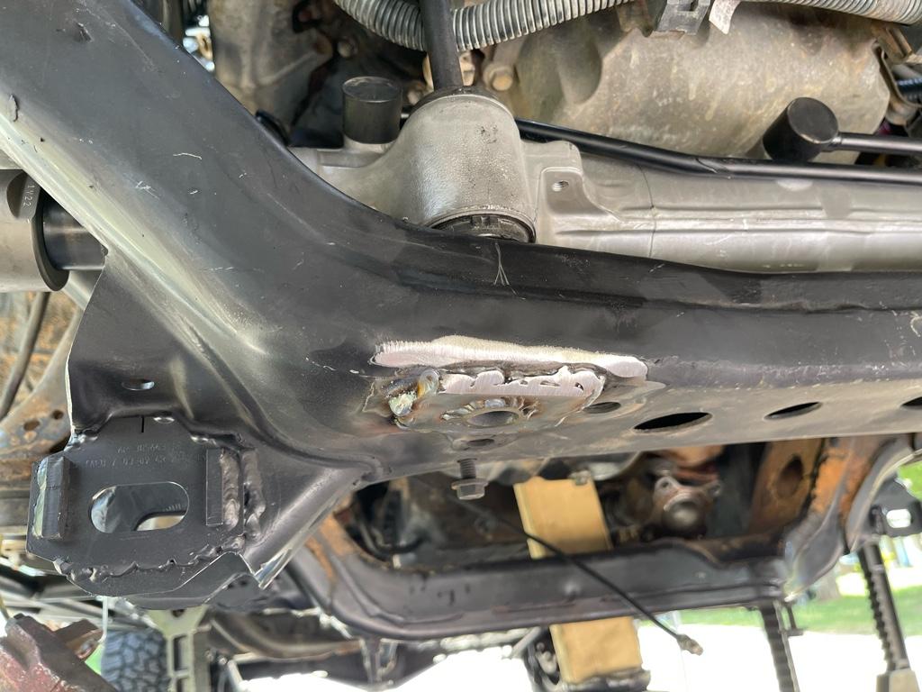
The nice thing about Devon's design, is you can take some measurements and move it around a little one way or another, before you drill the hole for the passenger side mount. (I used an old rear upper link sleeve to weld into this position for the frame support).

I focused on pushing it forward as much as possible as well as getting it centered side to side, and then squared it up w the core support. It's not perfect, but it's close.

I wanted it pushed forward to make sure the OTE clears the coil over through all the movement and angles it will see. This might bone me on the steering shaft clearance, but the coil over clearance is the most important parameter imo.

So as a reference, if your looking at the front from the bumper, the bolt hole in the bushing is between a 3 and 4 o'clock position on mine.

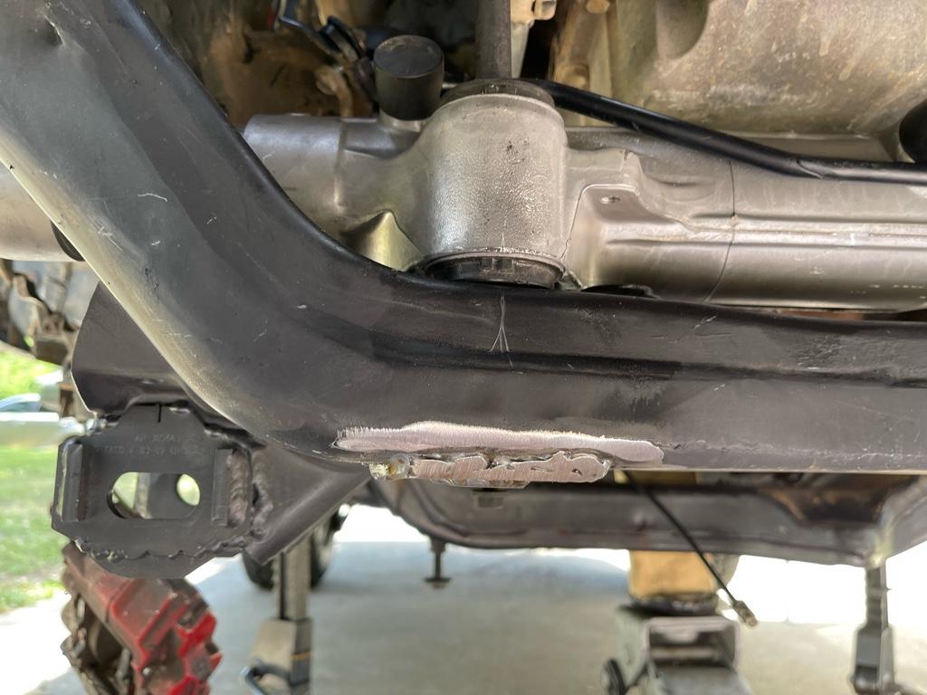
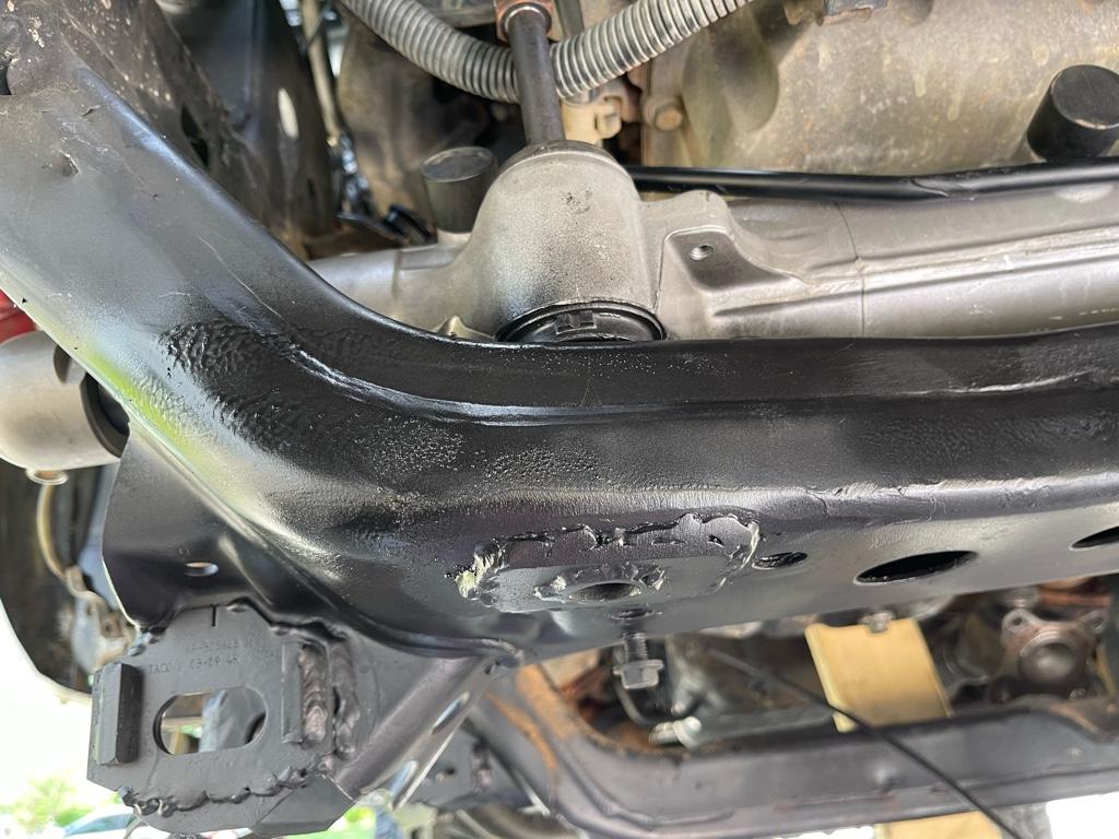
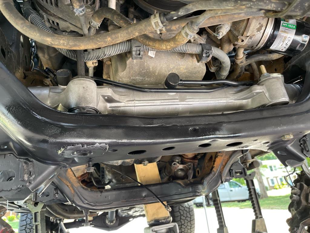
Also, the biggest mistake I made was cutting too much frame for the pinion clearance and had to weld some metal back in there to try and keep it from being too weak. This hole only needs to be about the size of a 50 cent piece.

Sent you a dm w my number. Gimme a call if there is anything I can help with.
Hell I might be calling you for advice when I do my final install....hopefully this freaking year lol.

Great input as always, I didn't think too much about ensuring clearance to the coilover.

I should still be on the right track with the plan, but in the test fitting portion of the rack it looks like I'll need to have the lower arms and coilovers mounted back. I'm not sure that I have a good way to test the full up travel with the springs as stiff as they are, but I guess we'll see how it goes..


Edit* And after typing this out I took a gander over onto Devon's write up and saw some recent discussion on there regarding the lc200 and outer tie rods... I am not in a bit of a panic... I may have overlooked quite a significant factor with my outer tie rod design... bigger may not always be better... my plan was to use a 3/4" bolt for tie rod on a 7/8" heim with high misalignment spacers... i saw your comment on potential rotor clearance and after taking a quick look at my rig I am not convinced that it will work.. lol. Oh oh... I don't have the outers with me at home to verify.. I think this could be rather quickly diagnosed by removing the factory outer and roughing in my new setup. The position is fixed so turning and articulating shouldn't make a difference.. so it will either fit or it wont. I'll need to figure that out before I drill out the taper for the 3/4" bolt.. I may be looking at going down to a 5/8" possibly.. but I guess we'll see. It will be a learning process.
=
I am also a bit upset that I just now learned about the doublshear conversion.. This could very well have been a possible solution, but we'll see, if this fits I can always fab up my own in the future.
 
Last edited:
Great input as always, I didn't think too much about ensuring clearance to the coilover.

I should still be on the right track with the plan, but in the test fitting portion of the rack it looks like I'll need to have the lower arms and coilovers mounted back. I'm not sure that I have a good way to test the full up travel with the springs as stiff as they are, but I guess we'll see how it goes..


Edit* And after typing this out I took a gander over onto Devon's write up and saw some recent discussion on there regarding the lc200 and outer tie rods... I am not in a bit of a panic... I may have overlooked quite a significant factor with my outer tie rod design... bigger may not always be better... my plan was to use a 3/4" bolt for tie rod on a 7/8" heim with high misalignment spacers... i saw your comment on potential rotor clearance and after taking a quick look at my rig I am not convinced that it will work.. lol. Oh oh... I don't have the outers with me at home to verify.. I think this could be rather quickly diagnosed by removing the factory outer and roughing in my new setup. The position is fixed so turning and articulating shouldn't make a difference.. so it will either fit or it wont. I'll need to figure that out before I drill out the taper for the 3/4" bolt.. I may be looking at going down to a 5/8" possibly.. but I guess we'll see. It will be a learning process.
=
I am also a bit upset that I just now learned about the doublshear conversion.. This could very well have been a possible solution, but we'll see, if this fits I can always fab up my own in the future.
I have seen where the Marlin setup eliminates the dust shield, so that may be an option, and hopefully you clear the rotor.
I can't remember, are you using the OE ITEs? It's an M22x1.5 diameter and thread count.
Edit: just read your dm. Don't reem the spindle until you can confirm what size bolt and heim your going to use. I unfortunately am stuck right now because I reemed mine out to fit the Tundra OTE and I'm not sure the amount of bump steer I see at full droop w the +3.5, will be safe.

All of this possible interference with the rotor is just speculation on my part as I have not mocked up a large heim, I could be wrong, but it has been mentioned in other threads.

Unfortunately you may have to remove the springs on your CO and cycle everything to see if it all clears. Maybe you could source a sleeve for the 7/8" heim to use a smaller diameter bolt during your mock up phase and see if it will clear the rotor, and not have to reem the spindle. That way you can put all the OEM stuff back together if you need to.
 
Last edited:
I have seen where the Marlin setup eliminates the dust shield, so that may be an option, and hopefully you clear the rotor.

I can't remember, are you using the OE ITEs? It's an M22x1.5 diameter and thread count.


I'm using the OEM LC200 inner yea, I was considering going the clevis setup, but after the whole bumpsteer convo I decided im staying stock on that side.


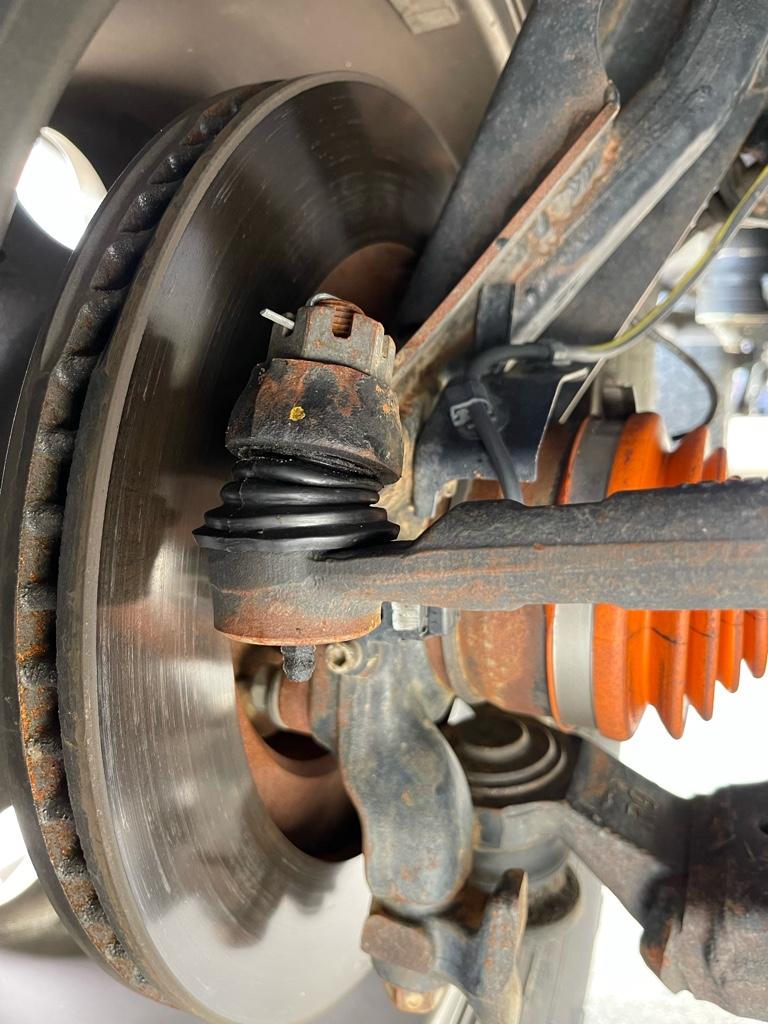
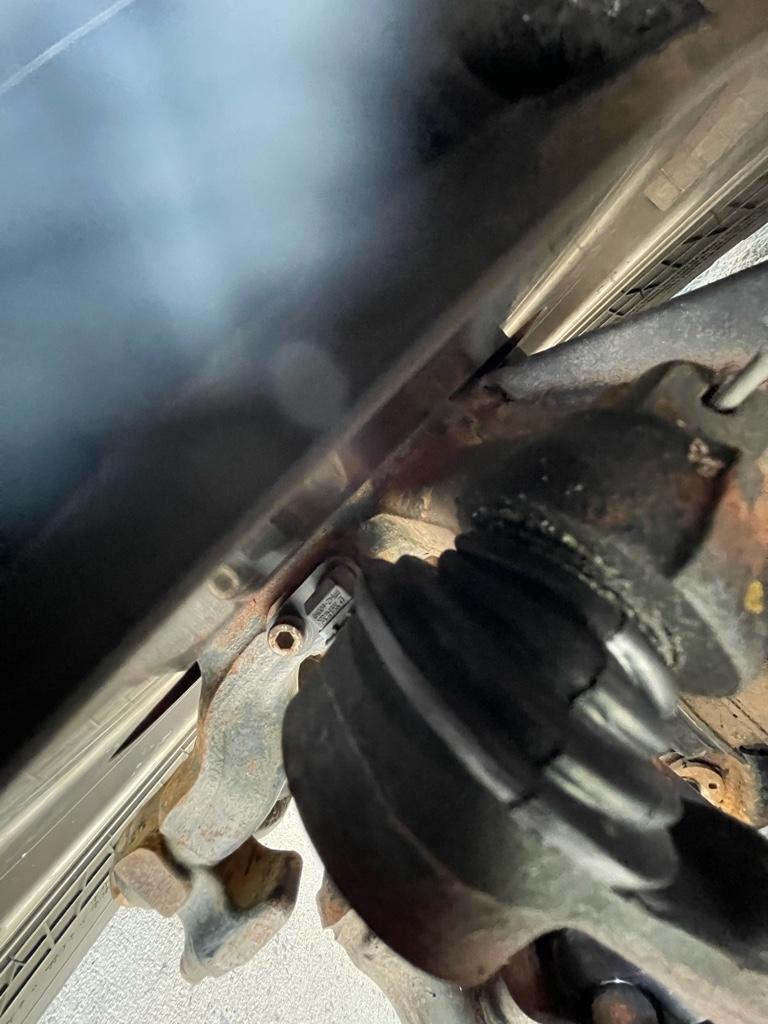
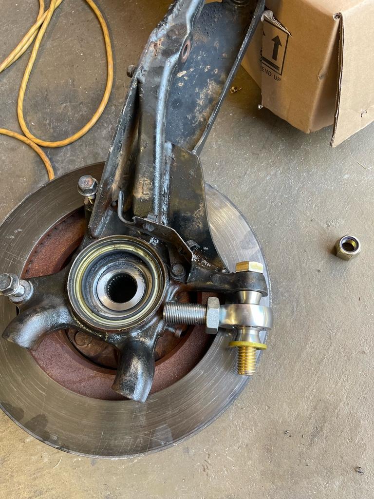
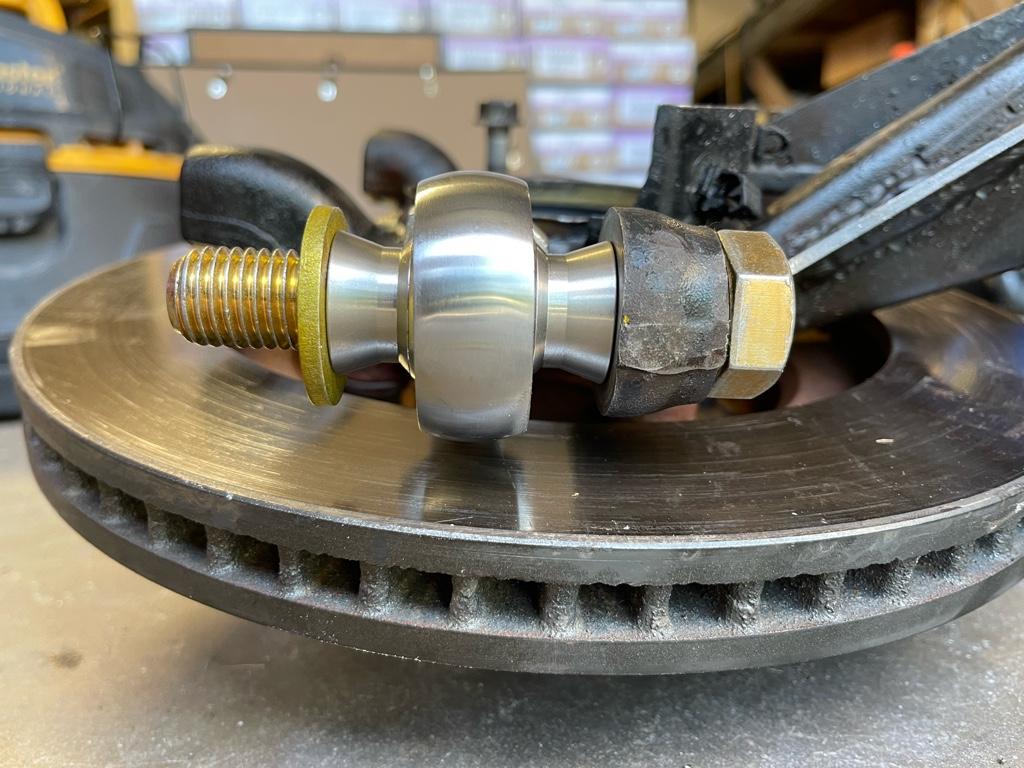
my dust shields are long gone after going with the Sport brake upgrade, so thats a none issue. I took a quick look just now again, and I think I should be OK.. it will probably be close, but should fit. There's probably close to 1/2" of space, if not more, between where the factory tie rod sits and the rotor, and from my pictures it doesn't look like the new hiem is THAT much larger .. we shall see..

ab3b666e02d6c1a9c0a0f0f8d78666ee.jpg

f19f00751360e920110a1107099d2b8b.jpg
 
Sick build. Just join this group due to researching on the LC200 rack swap on my 4th gen. Been a long time taco onwer and made the switch over to 4runner. Following you for build especially the lc200 swap.
 

Attachments

  • IMG_20220312_115212_675.jpg
    IMG_20220312_115212_675.jpg
    139.8 KB · Views: 219
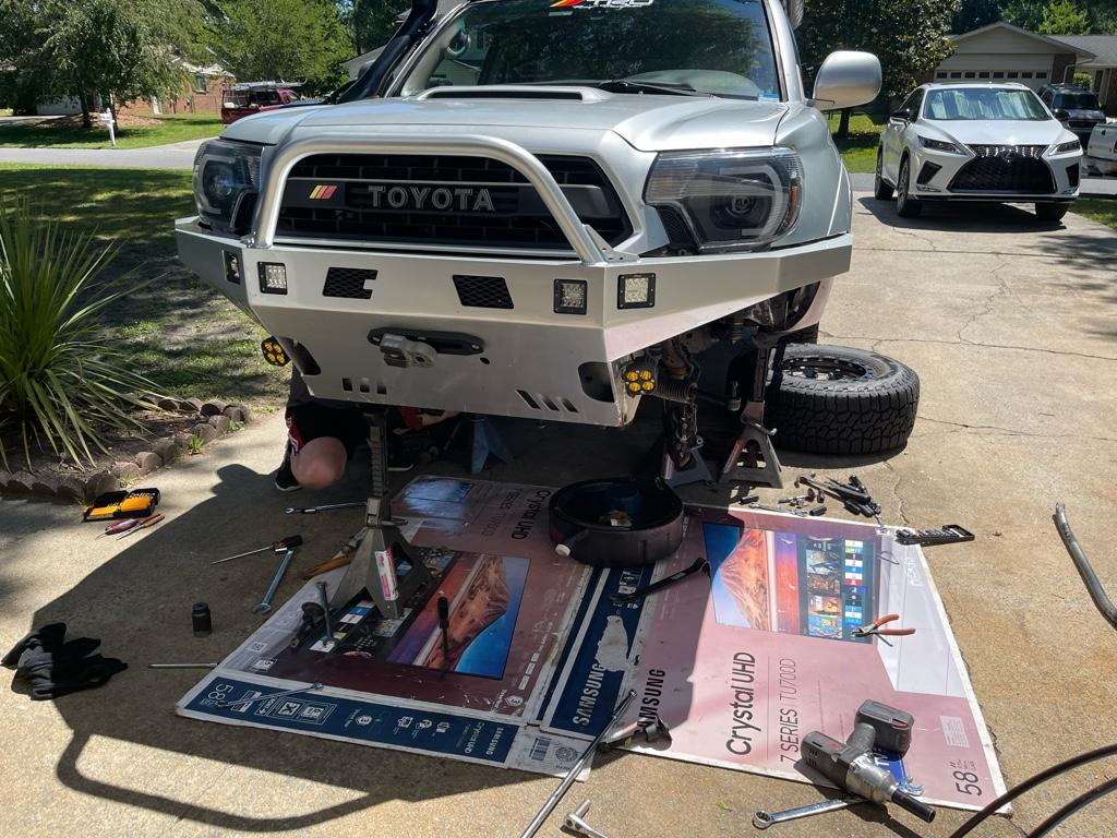
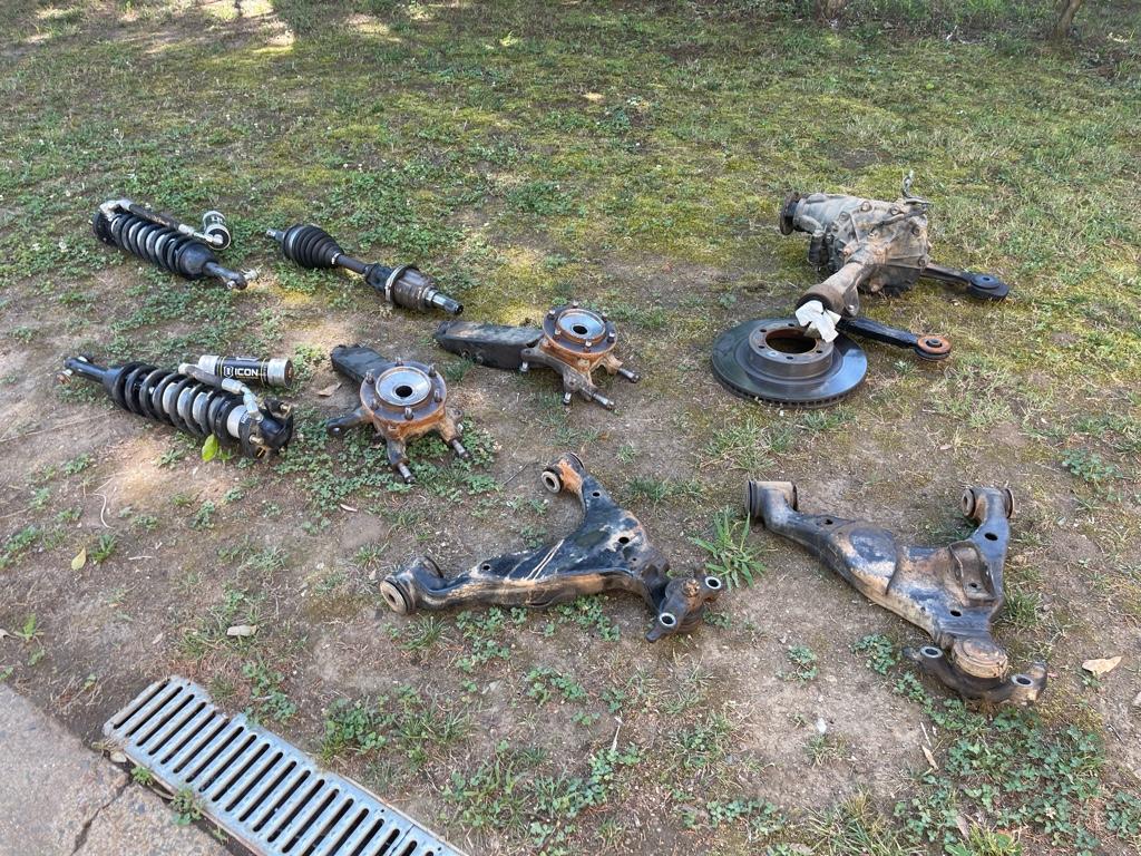
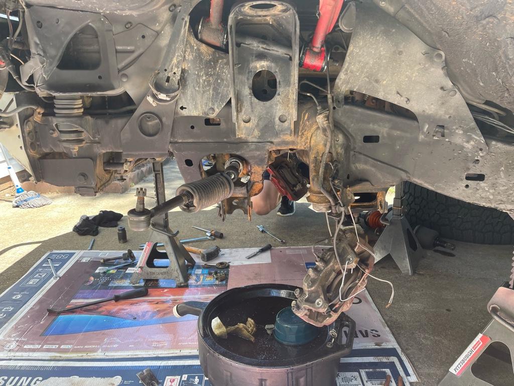
Well.. day one is a wrap.. I am absolutely beat. Working in the sun is just not my thing lol. After 7 hours of work I have the following :

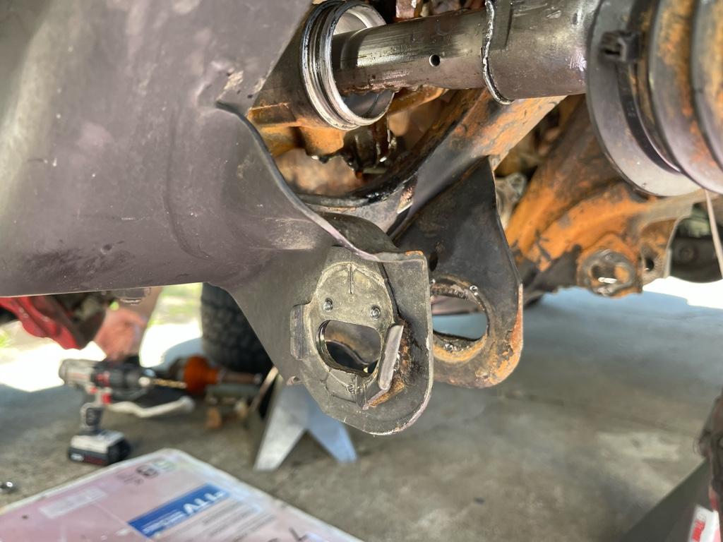
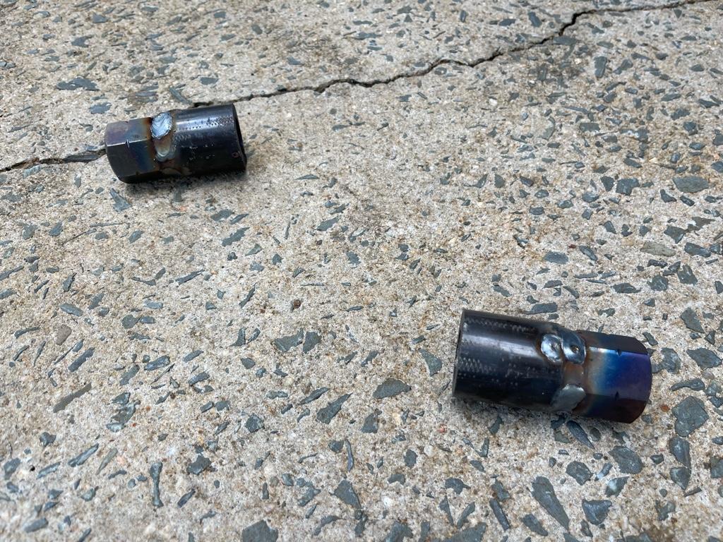
Everything is out , factory cam tabs are off, cam tabs are welded, outer tie rods are welded.


I did a rough mock up with the heim joint next to the rotor prior to taking everything apart and looks like I’m in the clear.. no pun intended lol. I don’t see myself putting the factory rack back in.. so We’ll see how it goes

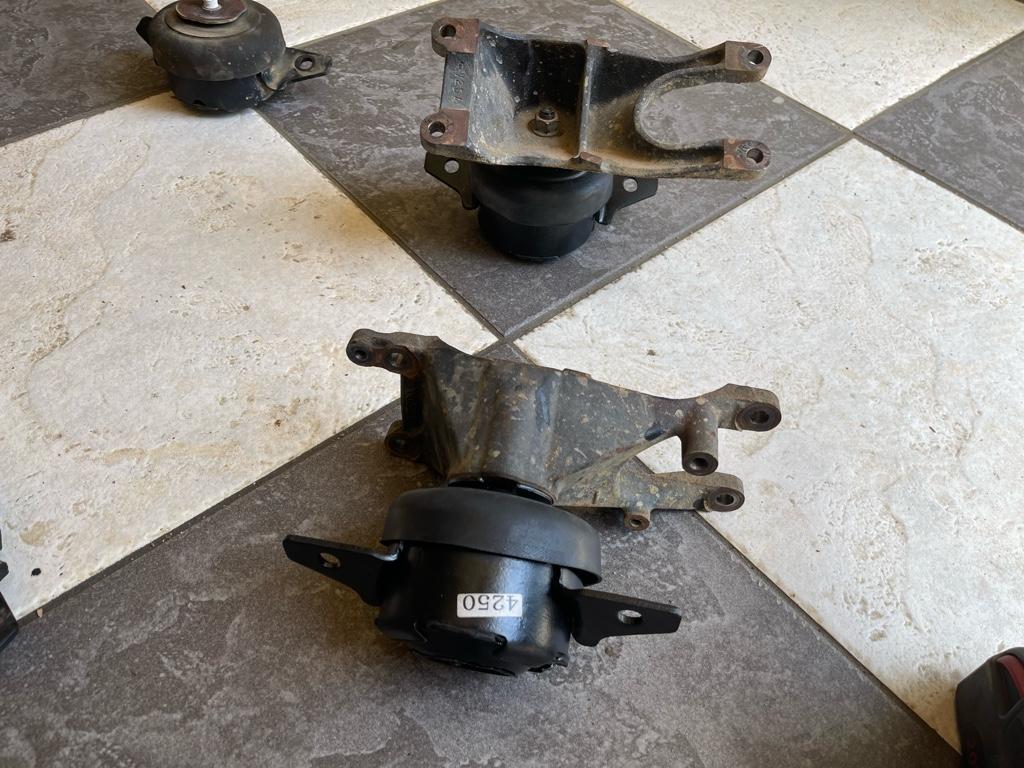
Replacing the motor mounts and adding the spacers is done .. but proved to be quite a pain in the ass.. I did not enjoy doing that lol.

After we pulled the rack and measured tie rod to tie rod I was pleased to confirm that my custom rods are just short enough to work. I’ll have probably 1/2” to spare. We’ll see how far I can get tomorrow.. this is for sure a big big project
c6ec62e56a19ceb2fe5945c81e7532fc.jpg

7050065d2b1a647bd86b573088a97d51.jpg

6795d74cc8ab822fe549c6b7de3de01b.jpg

fb44f4c3a316d1f8294a20623b7544e1.jpg

a4a488b2ceb6ff7ccc0e213b6533d5b7.jpg

4efa582c0ef98f64a98c709030d38efb.jpg

e0ba4a87ef4569e921c29bacf98734ae.jpg

041f094ffc572b5454c4fa7f369ae135.jpg

4fdd84e5152cebc748ecec86d0cba860.jpg


Sent from my iPhone using Tapatalk
 
I just decided there’s no way in hell I’m finishing this job tomorrow.. lol. There’s just too much to do, and working in the sun makes it that much slower.

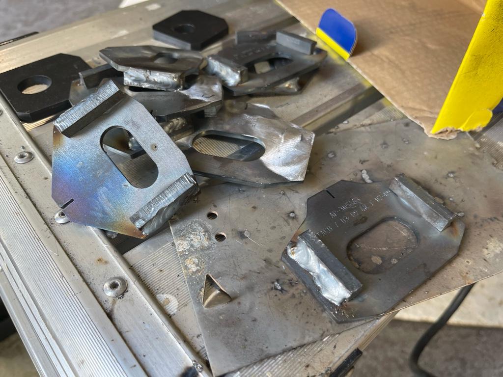
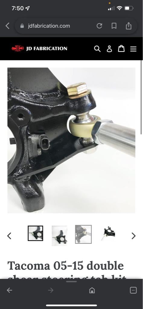
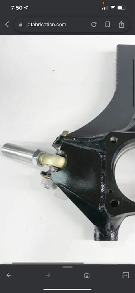
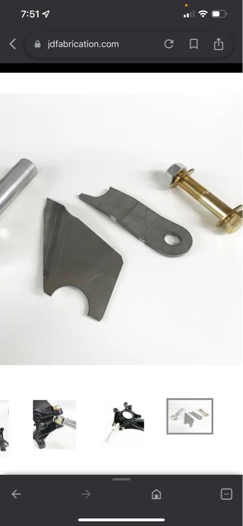
I also decided that there’s no reason to risk a single shear setup after going through all this trouble.. would be a damn shame to bend the bolt after doing all this work. Looking at this kit… I just can’t fathom paying $400 bucks for 4 pieces of flat steel and some heim joints.. lol. I can’t see why I couldn’t replicate this in a couple of hours with my 3/16” steel plate I have laying around. A couple of cardboard templates and a plasma cutter should do the job quick.

Things are getting serious.. but I haven’t really gotten to the “unknown” portion of the project , which is fitting in the rack and making sure everything is happy..

2e133412c739aa0ffdadaf4d4e4bcf73.jpg

59820cf72084c0c8da18251016fb37b2.jpg

b6d93ffe50d43a7ec9c29c791848d4ad.jpg


Sent from my iPhone using Tapatalk
 
They are proud of their shit over at JD Fab. Plus the cost of shipping from out west.

If you diy, please trace those cardboard templates and put em on a pdf. I'll send some cash your way. Wish I had Masons CAD skills.

I also need to learn how and where to source heims and misalignment spacers. All of these parts will need maintenance one day soon and paying top vendor dollar kind of bugs me.

Did all your OTE parts come from McMaster?

Kartek and McKenzies are good people, but their stuff aint cheap either.
 
I priced out the JD fab double shear kit a while ago, and sourcing my own heims and bolts it made sense to me to just buy the kit. IIRC it was like $200 for those 2 items then I'd have to design the metal.
 
They are proud of their shit over at JD Fab. Plus the cost of shipping from out west.

If you diy, please trace those cardboard templates and put em on a pdf. I'll send some cash your way. Wish I had Masons CAD skills.

I also need to learn how and where to source heims and misalignment spacers. All of these parts will need maintenance one day soon and paying top vendor dollar kind of bugs me.

Did all your OTE parts come from McMaster?

Kartek and McKenzies are good people, but their stuff aint cheap either.


Ruff stuff is where I’ve been getting most of Heims. Not cheap.. but decent. McMaster is out of hand coat wise but has a super huge selection.

I have about 200 bucks in my outer tie rod setup, but that’s including the dom tubing.

I’ll definitely try and grab a template if I go the diy route.. certainly doesn’t seem that bad to make


Sent from my iPhone using Tapatalk
 
They are proud of their shit over at JD Fab. Plus the cost of shipping from out west.

If you diy, please trace those cardboard templates and put em on a pdf. I'll send some cash your way. Wish I had Masons CAD skills.

I also need to learn how and where to source heims and misalignment spacers. All of these parts will need maintenance one day soon and paying top vendor dollar kind of bugs me.

Did all your OTE parts come from McMaster?

Kartek and McKenzies are good people, but their stuff aint cheap either.
JD fab is proud of their stuff, but Harry is really helpful and puts a lot of effort into the TW products. Some of the efforts he makes for customer service are really great. Personally, he shipped me another spindle gusset when I figured out one of the spindles I gusseted must have been bent a little bit. Another he time he offered to fully refund and take back a well-used slide rack that the guy didn't like that it wasn't holding up well to salted/sanded roads
 
Mid day check in.. much slower than anticipated, far from a 2 day project to get everything done , but the test fit #1 of the rack is a success.

Cam tabs are welded on and painted as well.

I’ll put up a more detailed post later.. but will say that I don’t current see a way to get this thing in with the diff and most of the suspension in place.. it was tight. Pulling off the tie rods would certainly help, but with how tight they are I feel like it was easier to just drop the diff and give yourself plenty of room to work.

Also started drilling out the spindles.. and doesn’t help forgetting the nice corded drill at home.. the 18v is not happy and I don’t think I can get these done today. Drill bits aren’t all that sharp either so we’ll see what I can do with these at home .. not looking forward to it at all
75bdc693a10cd797120dcfd944565779.jpg

470db7bf409baed5d1801405fdf2e0da.jpg

ced09da187855b8cccd40fab3089084e.jpg

fbf9809e8c0db461754daa52949bc9c9.jpg

a225063476c6def89740994ce4537e84.jpg

5d8133f87fbd701e1d7bcb4757562d99.jpg

8eb53a1ab7cd2b3c8a0a3c0c489fed56.jpg

53a6af1af6a536d3d3793cdd6a1a098a.jpg


Sent from my iPhone using Tapatalk
 
Yup … I grossly underestimated the scope of this project. Day two complete and the only progress I made today is mourning the rack, Reinforcing the passenger side mount point and getting the cam tabs welded.


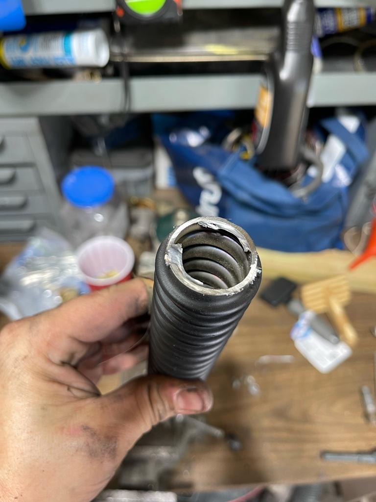
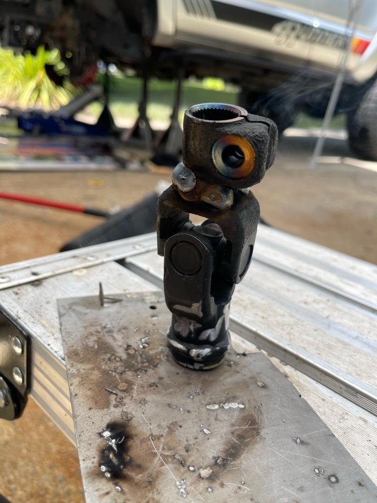
I quickly found out that there is no way to make the factory steering shaft work without modifying both it and the drivers side engine mount. I started the shaft already but need to get some tubing to finish it.

0c846204a064f40ad100762034ccfd9a.jpg

4734bf7f10896106db9fb080916abc7e.jpg

9a830416bc6ee6b845979ff17bf1be0d.jpg

353001773629a6e9ccbc66a8ed437329.jpg

0c0c7e0a4fc7d3313bdbe9d24d874cf2.jpg

d82ab71c480347913ccc12af213c4c6d.jpg

a5a0506ef7342ec300a3c1e6e77a8932.jpg


Sent from my iPhone using Tapatalk
 
You have quite a bit done actually, turning wrenches on a driveway in the Sun. It's not easy working like that.

I'm really slow and deliberate, because if I rush or set a time line, it ends up bitin me in the ass. And once I get aggravated, the truck usually wins that round.
 
Steering shaft too long?


Not too long, too thick and bulky around the engine mount. I saw some of your pictures of it modified a similar way I believe ? Did you cut it down any? Or just replace the ribbed section with a thinner tubing to clear the engine mount.? I cut a good chunk out of the corner of the mount already and will need to fab something up to reinforce it.. not the greatest clearance to work with but it’s gotta be done , last thing I need is the mount sagging after doing all that work lol.


*EDIT* I just realized that wasn't your post on the other forum showing the modified steering shaft. I'll grab some pictures of it in the next couple of days, but basically the U joint sits right up against the bottom of the motor mount as is, so cutting a bit of length out of it helps clear that section. The ribbed shaft it self it hollow and quite large in diameter, so I am in the process of ordering a 1" OD tube with .12" sidewall from McMaster so I can weld it in place and hopefully clear the rest of the mount.. I'll have to cut some material and reinforce it some before i'm done.. I cut a decent chunk out of it..

Sent from my iPhone using Tapatalk
 
Last edited:
No going back not (not easily at least lol).

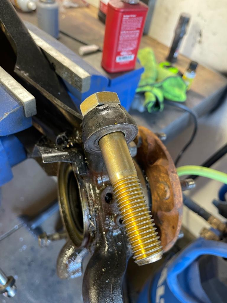
Decided to give one knuckle a go after unpacking the tools… I’m pleased to say, that so far I don’t see any issues clearing a 7/8” heim with a 3/4” bolt.

Not too thrilled about laying out the doubleshear template, but that’s probably because I’m beat done after 2 hard days in the sun lol. Getting closer..

73906c9730010c0cd80f82e544d4d454.jpg

963fb619268f9d96ff16e491d143d5d9.jpg

7a1d69ddec3f93f3d220f42a4cfd126e.jpg


Sent from my iPhone using Tapatalk
 
Now that i've had a little time to rest up from an eventful weekend I wanted to drop a few insights from the swap thus far..

This is definitely a very sizeable project. Unless you have a full shop with a lift and a ton of free time to dedicate to this, dont plan to knock this out in a weekend. I certainly didn't even come close. And that doesn't even include the couple of hours I spent earlier getting the custom outer tie rods fabricated.

Granted I was also in the process of doing the total chaos cam tabs, I still don't see a way to have gotten this done much quicker, and not to mention, I think these are a perfect combination of projects to tackle together.

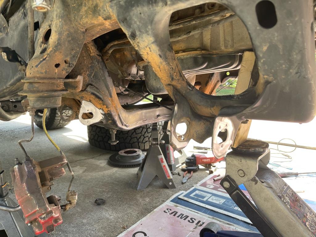
Another note is that I just don't see an easy way (if at all) to work on this rack swap without dropping the diff.. just pull the diff if you're going to do it, I feel like it will save you time and frustration. It's literally 7 bolts and 2 axles, which pretty much have to come out any way.. so yea.. just do it lol.

Not having the lower control arms hanging down also was a huge help. The only thing that remained on the rig were the uppers.

The motor mounts were a lot tougher to do then I expected.. it's a super tight fit to get the up and out of the rig. I also absolutely despise the engineer that came up with this moronic design of having to remove the motor brackets to take out the mount, but hey, it's done now lol. Definitely do NOT tack weld the 1/4" spacers to the mounts. It will make your life hell trying to get that in like that. They are super easy to get into place after.

Also, I found that I need to lift the motor back up in order to manipulate the rack in and out (like 10 times during the hole process) so don't crank down on them until you're all done.

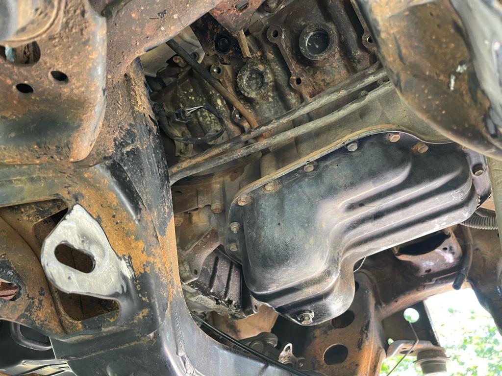
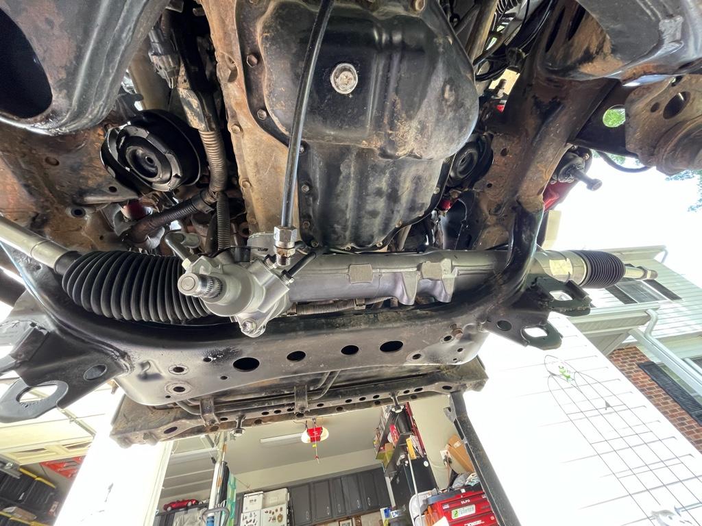
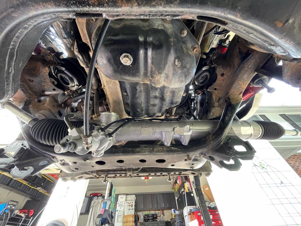
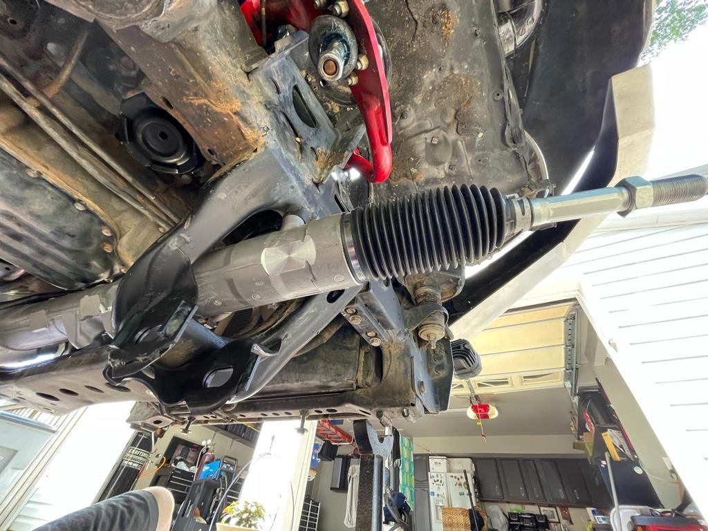
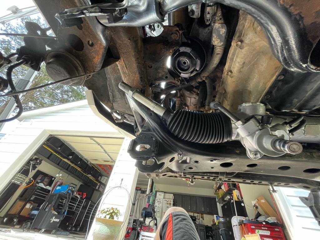
To initially get the rack in, what I did was come in from under the subframe, got the passenger side tie-rod into the opening and muscled it as far as I could while turning it slightly to clear the hoses and mount to a point where I could get the drivers side tie rod up and into the opening as well. Once the rack was in, I didn't have to fully remove it to do what I needed. Pulling it as far out to the passenger side gave me sufficient room to do all the cutting and grinding to get it where it needed to be.

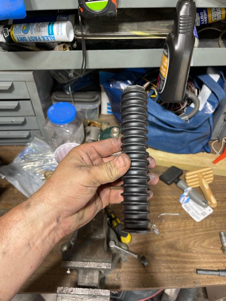
Centering and squaring up the rack in the subframe was surprisingly not all that difficult to do. I first found out that the rack itself was slightly turned out to the left, and the best way I found to square it up was to remove the boot and just measure from the rack face out to the inner face of the inner tierod.
Once I got the tie rods evened out on both sides I just picked 2 places on the subframe to measure from to the rack and make small adjustments in the offset bushing. I ended up with the rack being 4" back from the front face of the subframe to the center of the tie rod ball joint, and I think something like 7 3/8" diagonally from the top of the subframe to the tip of the threaded inner tie rod end. Both sides were within 1/16" of each other so I'd say it's pretty close... (if the subframe is truly all square lol, if not I may be all sorts of messed up but certainly looks close).

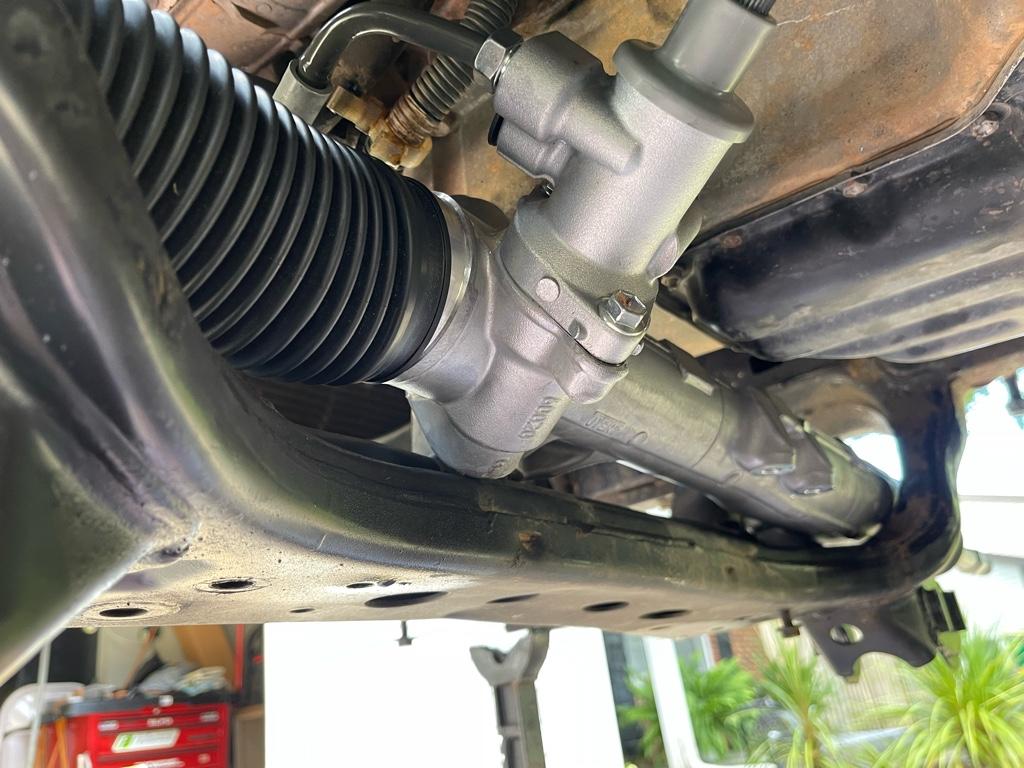
Because of the way the offset bushing moves the rack (both front/back and left/right) as it spins, there really isn't ALL that much wiggle room you have to shift it forward of backwards if you want it squared up. I got it as far forward as I could manage while keeping the measurements somewhat even. If you are looking at the rack from the front/top, my offset bushing position is some where around 1-2 o'clock. I have not verified if it hits the coils any, but honestly.. there's not much I can do if it does.. there is some adjustment, but not a ton so I guess fingers crossed on that.. I ended up shaving a bit of the subframe under the drivers side rack mount to allow it to sit lower into the frame, definitely didn't take much, and there is a little interference still, but I'm just doing to leave it as is, I don't see it hurting anything. The rack should be torqued down quite a bit and not move any so I don't see it causing any noises or vibrating itself into trouble.


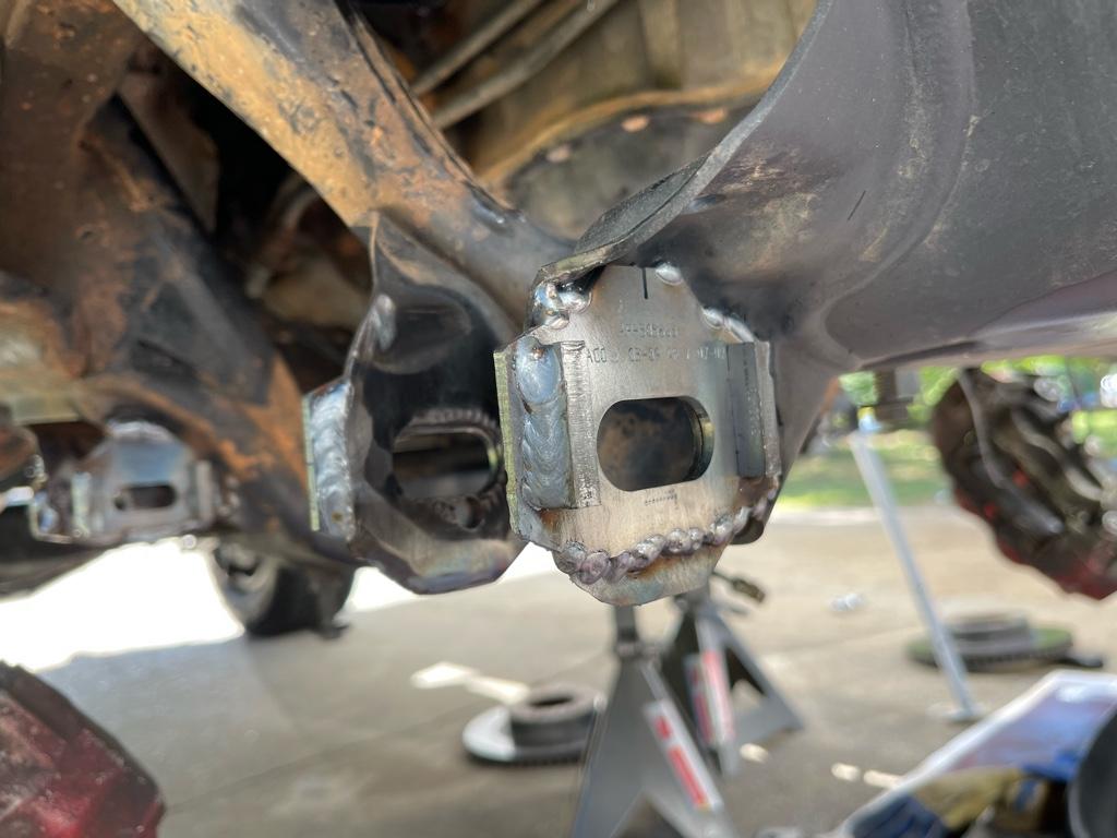
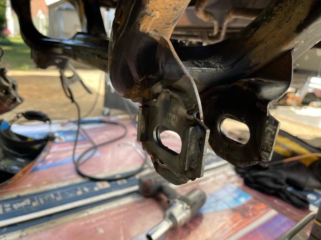
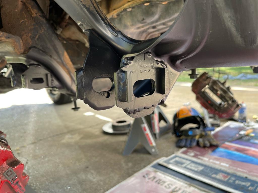
after I got the position where I wanted (after moving the rack in and out quite a few times, I got really quick at it by the end), I roughly marked the passenger side mount position and went to town with the drill. I ended up being off slightly with my position, but because the reinforcement tube I am using was larger than the bolt but a bit I was able to make it work. I cut the tube to bottom out against the top of the subframe and welded it with the plate to the bottom. I don't have it welded at the top, it is just snug against the inside face and can't go anywhere and will do the job of not allowing the subframe to crush as I tighten the mounting bolt. I feel like having a larger plate to weld is a must to help distribute some of the force even more and give you some wiggle room if you miss your mark on the exact centerline of the rack mount.


Next up, and the only BIG project left, is to make the steering shaft work.. I felt pretty terrible about cutting up a brand new, not so cheap, shaft... but I think it was still worth the money, especially since I have to make it custom and having new U-joints should help it last longer over the 150k miles factory one. I'm keeping it just in case I screw up and need to do something different.

The u-joint near the rack literally sits against the motor mount, no way of making it work unless maybe you made a completely custom double cardan joint to sweep around the mount.. I don't have that ability so I resorted to the cutting wheel.. a plasma torch would have been quicker, but something about laying under molten metal and not seeing what you're potentially torching on the motor on the opposite end steered me away from that option (no pun intended :) ).

I found some pictures of the modified shaft on the FJ cruiser forums, and it basically cut down the spline tube as short as possible on one end to move the u-joint closer to the rack and away from the motor mount, and also cut out the larger diameter ribbed steering shaft and replaced it with a smooth tube (that seems to be approximately 1" OD. I have a 12" long piece of 1" OD, .12"side wall tubing coming from McMaster later today or tomorrow and am planning on welding that in place. I don't yet know if I need to shorten or lengthen it at all, so one step at a time I guess.

I'll also need to figure out how to reinforce the motor mount again after I fit the shaft. One thing I am a bit concerned about is how much the body flexes over the frame when fully articulated. I don't have a way to simulate that .. so I can't test to make sure I have sufficient clearance on the steering shaft.. so I guess time will tell.

and for the last chapter in my overly long, none-picture book, goes to modifying the spindle. You definitely want a corded drill at the least.. better yet.. if you have a way to get these on a drill press you'll be a happy camper. My corded drill with a 3/4" drill bit did the job, definitely Low Speed and Lots and Lots of Feed was the trick, along with a tone of cutting oil. You want a nice sharp bit for this. The issue with doing this by hand is that if you're not careful your bit will wobble on you and slightly oversize your hole. If it's too larger the bolt will have slop.. luckily for me it looks like it should be fine, but certainly is a hair over 3/4" for sure.. maybe better to have done it with an undersized bit to see if I could get the clearance that way so I have an 18.5mm drill bit from amazon on the way.

So yea... that's where I am.. :)

 
Damn, Not lookin forward to the steering shaft fix.

DocME in the FJ forum has a pic of his patch for the MM clearance, if you haven't already seen it.

Maybe he has a couple tips...
Just curious, you have a body lift on your Runner?
 

Members online

No members online now.

Forum statistics

Threads
278,312
Messages
3,554,083
Members
248,016
Latest member
Advally Service

Trending content

Back
Top