Best Dual Battery Setup for a 5th Gen 4Runner

Edit: You also mentioned 300A fuses and 4 AWG wires... I think that fuse is way over-sized for a 4AWG cable. Combine that with the heat in the engine bay and you don't have sufficient protection for the wiring. I would up-size the wires, or I would reduce the fuse value. I generally run 100-140 amp fuses on 4 AWG lines depending on the length of the run.

Thanks [MENTION=144483]Bumbo[/MENTION] for you input. I was actually really hoping you would engage my post as you really seem to have a firm grasp on this stuff. I am actually using 2/0 AWG wire to connected my start and house batteries to the ACR. Those will be protected on each side by the 300amp fuse. I was thinking of using the 4AWG to augment the existing 8AWG battery-chassis ground and if that would be sufficient so that I could then chassis ground my house battery. Sounds like maybe I should directly ground the two together. I really like your thoughts of force combining the batteries for winching.

-T-
 
Thanks [MENTION=144483]Bumbo[/MENTION] for you input. I was actually really hoping you would engage my post as you really seem to have a firm grasp on this stuff. I am actually using 2/0 AWG wire to connected my start and house batteries to the ACR. Those will be protected on each side by the 300amp fuse. I was thinking of using the 4AWG to augment the existing 8AWG battery-chassis ground and if that would be sufficient so that I could then chassis ground my house battery. Sounds like maybe I should directly ground the two together. I really like your thoughts of force combining the batteries for winching.

-T-

Just adding random ground legs and augmenting smaller cables with larger cables sounds great until it catches on fire because you didn’t correctly plan your power return path.

You can’t guarantee that power will flow proportionally though those different sized wires. If for some reason that 8AWG has a lower resistance path back to home (4AWG hardware came loose, dirt, corrosion over time, poor install) your chances of having an electrical fire skyrocket in high load conditions.

IT’S A CIRCUIT… I think it’s very important for people to realize that when doing wiring work like this, to know power has to circle back to “complete the loop”. The circuit is only as good as its weakest component… which should be the fuse in a correctly designed system.

If you +/- is wired directly to the battery using dual bus fuse blocks or bus bars then GREAT, but if you do like the car stereo people and ground to the chassis, it’s going to matter heaps as a return path is though the factory ground wire.

If you have 300A positive legs for service, you better have the same capability back to the battery to compete the circuit.

Remember, it’s all in how you wire it too… even if you wire the two battery grounds together with big cable, and then decide to ground the winch to the frame, guess what wire gets to be the ground path back to the battery? If you wire it where the ground never returns though the chassis, then leaving it stock wire size would be 100% sufficient; + any equalization current between the two batteries if you didn't have the battery grounds wired directly to each-other.

This is why I am a huge fan of those fuse blocks that have both positive and negative bus as part of the unit with both +/- have direct connections back to the batteries.
 
Last edited:
The PC1500 does fir the Shrockworks tray, however, keep in mind there is no room at all for wiring to run between the fender wall and battery. Still great to know for anyone who wants that extra bit of power.

Beautiful installation. Just wondering why you went with the 34/78 over a 34? Because of the extra terminal to keep things cleaner?

Also, do you remember where you got that triple terminal post? I can't seem to find anything like that online.
 
Just adding random ground legs and augmenting smaller cables with larger cables sounds great until it catches on fire because you didn’t correctly plan your power return path.

You can’t guarantee that power will flow proportionally though those different sized wires. If for some reason that 8AWG has a lower resistance path back to home (4AWG hardware came loose, dirt, corrosion over time, poor install) your chances of having an electrical fire skyrocket in high load conditions.

IT’S A CIRCUIT… I think it’s very important for people to realize that when doing wiring work like this, to know power has to circle back to “complete the loop”. The circuit is only as good as its weakest component… which should be the fuse in a correctly designed system.

If you +/- is wired directly to the battery using dual bus fuse blocks or bus bars then GREAT, but if you do like the car stereo people and ground to the chassis, it’s going to matter heaps as a return path is though the factory ground wire.

If you have 300A positive legs for service, you better have the same capability back to the battery to compete the circuit.

Remember, it’s all in how you wire it too… even if you wire the two battery grounds together with big cable, and then decide to ground the winch to the frame, guess what wire gets to be the ground path back to the battery? If you wire it where the ground never returns though the chassis, then leaving it stock wire size would be 100% sufficient; + any equalization current between the two batteries if you didn't have the battery grounds wired directly to each-other.

This is why I am a huge fan of those fuse blocks that have both positive and negative bus as part of the unit with both +/- have direct connections back to the batteries.

You know ill admit I never really thought of this. I plan on running a 4AWG (Pos) wire from my rear fuse block to my house battery. Was also planning on grounding it locally with a 4AWG wire to the rear chassis. Are you saying by doing that it will essentially flow through the main starter battery's OEM chassis ground? I have the starter and house batteries negative posts linked up.

Might not be an issue since I won't be exceeding 50A. However, I was just thinking of how I have my winch directly hooked to the starter battery both (+) and (-). Wouldn't the winch's 450+ amps at load be going through that 8AWG OEM chassis ground for the main battery?
 
You know ill admit I never really thought of this. I plan on running a 4AWG (Pos) wire from my rear fuse block to my house battery. Was also planning on grounding it locally with a 4AWG wire to the rear chassis. Are you saying by doing that it will essentially flow through the main starter battery's OEM chassis ground? I have the starter and house batteries negative posts linked up.

Might not be an issue since I won't be exceeding 50A. However, I was just thinking of how I have my winch directly hooked to the starter battery both (+) and (-). Wouldn't the winch's 450+ amps at load be going through that 8AWG OEM chassis ground for the main battery?

That is precisely what I am trying to say… in your scenario without a dedicated return path the current will flow though the chassis, though the OEM chassis ground, and then through the linked ground connection between the two batteries before it completes the rear fuse block circuit.

If the ACR is closed, meaning both cells are in parallel, then the only difference is that the current flowing though the linked ground between the two batteries will be reduced as the starter is also participating in feeding the house loads… but the full current draw is still moving though the OEM chassis ground. It’s also very easy to test/prove with a DC clamp meter.

I too have a rear/in cabin aux fuse panel, and I have both POS and NEG legs wired directly back to the house battery to eliminate this from happening. Everything I have in terms of fuse panels have their own direct path back to the battery.

TudRiU1.jpg


None of this matters much if you are moving small loads, but the second you start throwing a winch into the conversation that can have a peak draw of 300-400 amps, you need to look harder at these things during operation.

The easiest thing to do with high amperage loads (like your winch) is wire both positive and negative directly to the battery. That said, in your scenario, you have a dedicated ground cable between the two batteries, and the winch wired directly to the starter battery. The high current path in your situation is not though the OEM chassis ground, it’s between the ground link between the two cells, and the automatic charging relay (if that’s what you are using).
 
Last edited:
Just adding random ground legs and augmenting smaller cables with larger cables sounds great until it catches on fire because you didn’t correctly plan your power return path.

Remember, it’s all in how you wire it too… even if you wire the two battery grounds together with big cable, and then decide to ground the winch to the frame, guess what wire gets to be the ground path back to the battery? If you wire it where the ground never returns though the chassis, then leaving it stock wire size would be 100% sufficient; + any equalization current between the two batteries if you didn't have the battery grounds wired directly to each-other.

This is why I am a huge fan of those fuse blocks that have both positive and negative bus as part of the unit with both +/- have direct connections back to the batteries.

Thanks for this. I don't have a winch at present so for now I've simply upgraded my chassis ground from 8 to 4 gauge. I do still plan on chassis grounding my house battery as I don't see it currently being an issue with my low amperage constant draw planned for the house system (Fridge, CB, etc...). However, if and when I decide to get a winch, I will either upgrade the start chassis ground to 1/0 or simply connect the winch to the start battery and avoid ACR system altogether. That system is protected by 300 amp fuses and thus they could blow if I connect to the house battery. Thanks again for your input.
 
Dave...your NL brackets look great. In case you ever make another round or have one laying around, I'd be interested.
 
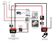
Thanks to all the great advice in this thread! I'm about to tackle this myself and I've been reading every thread and build that I can find. I think I have it figured out but I'm looking for extra eyes as I'm only really experience in AC 120v. Here is what i'm thinking with the parts I'm looking to get.

t4r dual wiring.jpg

I think my main question is grounding the Powertray with the switchpro and fuse block. My diagram shows it going back to the house battery but Powertrays sells a ground cable from the ground bus back to the factory ground. Is this Ok? It will be max 100 amp.

Final wire size to be determined via the BlueSea cable sizing app. Cable between batteries will depend on if I chose 150 amp fuses or 300 amp. I'm leaning towards 300amp in the event a winch is somewhere down the road.

Thanks
 

Attachments

  • t4r dual wiring.jpg
    t4r dual wiring.jpg
    116.2 KB · Views: 18,355
A couple of thoughts. First, it looks like you are connecting your switch pro to your Blue Sea 6 circuit fuse block. The switch pro is already protected by it’s own 125 amp fuse and can supply 4 35 Amp circuits and 4 18 Amp circuits. If you connect the Switch pro to that fuse block, I don’t think you are going to find a large enough fuse for that fuse block to supply the Switch Pro. You run the risk of overloading this circuit. Plus, it is excessively redundant. I would just connect the switch pro directly to the house battery; remember it is already protected by it’s own fuse. Second, it appears that you are going to supply power to your RTT accessories off of a BusBar. I would presume that you are going to fuse protect each of your accessories. Again, this is a redundant system and you could overload the 6 circuit fuse block. What I would do with this is put the BusBar between the 100 Amp Blue Sea 285 circuit breaker and the fuse block. I am using the BusBar pictured below in this exact manner. I am connecting 4AWG off of a 100amp main breaker to the main BusBar input, running a couple of small things off the small outputs in the middle, and then continuing on to my 6 circuit fuse block by running 4AWG off the other side of the BusBar.
9c5951899f182a177aed9ac6db63ec2d.jpg


Finally, I am also using the Shrockworks ACR and Fuse mounting tray under my start battery. I mounted the ACR 7622 on this tray. I found that I it rubbed just a touch against my radiator line. I bent it in by hand just a touch to gain about an 1” of clearance.


Sent from my iPad using Tapatalk Pro
 
Last edited:
Thanks Delgadtn! I did see where you had to bend the line out of the way. That center section of my diagram is confusing. I wont run the power to the switch pro through the blue sea fuse box. Was hoping to avoid 2 wires as the fuse block and switch pro will sit on the same tray but one is 100 amp and one is 125. It looks like the fuse block will accept a 125 amp max fuse for protection so could I use the one line and combine at the positive terminal of the block to feed the switch pro? It won't run through the fuse block as a circuit.

The 10 screw bus bar will be grounding for switch pro accessories and 8 terminal block will be for the positive connections on the switch pro. The Power tray set up is nice with the switch pro and circuit fuse box all mounted to it. RTT will be on a switch pro circuit so I can control remotely. Fridge and USB will be off fuse panel. Only thing else planned is some lights for now.

Thanks again for the feedback. Everything helps, while I've wired houses, this is my largest DC project and I don't want to mess it up!

Sent from my SM-G950U using Tapatalk
 
Last edited:
I wont run the power to the switch pro through the blue sea fuse box. Was hoping to avoid 2 wires as the fuse block and switch pro will sit on the same tray but one is 100 amp and one is 125. It looks like the fuse block will accept a 125 amp max fuse for protection so could I use the one line and combine at the positive terminal of the block to feed the switch pro? It won't run through the fuse block as a circuit.

Sent from my SM-G950U using Tapatalk


Yes. You could do that as long as you watch your amperage. The fuse block and the Switch Pro would be connected in parallel based on the setup described. This circuit has the potential to place up to 225 amps of demand on the system. As long as the wire and breaker used running from the house battery to the block can handle that you would be fine. You would probably need to run 1/0 or even 2/0 in this setting.


Sent from my iPhone using Tapatalk Pro
 
Hey, sorry I'm a little late to the party. I'm just about to install my dual battery/accessory fuse box setup and Chrisinvermont's diagram is helpful, but also has me a bit confused. Off my house battery (connected to start/alt by ML-ACR, I was planning on running a breaker and then a Blue Sea 12 circuit fuse box. From the box, I will wire up my own leads/relays (I have no sPOD/switchpro) for the following switched accessories: LED bumper lightbar, LED rack backlights, ARB airpump (engine bay), and an AUX anderson plug for camping accessories in front bumper. Then was thinking that I would run a lead back to a smaller fuse box in the cargo area (for LED interior lights, always hot USB, and either an AC converter or Anderson plug for future fridge and battery/laptop chargers). My plan was to run all grounds back to the originating fuse box.My question is, should I run the cargo fuse box off the engine bay house battery fusebox, or should I run a seperate circuit direct from the house battery? Or (more likely) is there a better way -- am I missing something altogether and need to rethink this wiring? Thanks.
 
Last edited:
Hey, sorry I'm a little late to the party. I'm just about to install my dual battery/accessory fuse box setup and Chrisinvermont's diagram is helpful, but also has me a bit confused. Off my house battery (connected to start/alt by ML-ACR, I was planning on running a breaker and then a Blue Sea 12 circuit fuse box. From the box, I will wire up my own leads/relays (I have no sPOD/switchpro) for the following switched accessories: LED bumper lightbar, LED rack backlights, ARB airpump (engine bay), and an AUX anderson plug for camping accessories in front bumper. Then was thinking that I would run a lead back to a smaller fuse box in the cargo area (for LED interior lights, always hot USB, and either an AC converter or Anderson plug for future fridge and battery/laptop chargers). My plan was to run all grounds back to the originating fuse box.My question is, should I run the cargo fuse box off the engine bay house battery fusebox, or should I run a seperate circuit direct from the house battery? Or (more likely) is there a better way -- am I missing something altogether and need to rethink this wiring? Thanks.

It’s called a sub-panel… and its perfectly acceptable to run another circuit off the main fuse block to feed another fuse block.

I did the exact same thing in my truck… I have a main engine bay 12 circuit feeing a smaller 6 circuit inside the cab.

The only downside of doing this is you would be limited to max single circuit amperage of that 12 circuit block which I believe is 30 amps for the sub-panel. For the loads you are running (interior lights, hot USB, fridge, small inverter) should be totally fine. Even if the combined amperage of the 6 circuits is more than 30 amps its ok since its unlikely everything is used at the same time, and you still have a 30A fuse on the main to protect the branch.

On the plus side, if you ever needed to isolate / service anything behind the subpanel or the subpanel itself, all you need to do is pull a single fuse from the main panel.
 
It’s called a sub-panel… and its perfectly acceptable to run another circuit off the main fuse block to feed another fuse block.

I did the exact same thing in my truck… I have a main engine bay 12 circuit feeing a smaller 6 circuit inside the cab.

The only downside of doing this is you would be limited to max single circuit amperage of that 12 circuit block which I believe is 30 amps for the sub-panel. For the loads you are running (interior lights, hot USB, fridge, small inverter) should be totally fine. Even if the combined amperage of the 6 circuits is more than 30 amps its ok since its unlikely everything is used at the same time, and you still have a 30A fuse on the main to protect the branch.

On the plus side, if you ever needed to isolate / service anything behind the subpanel or the subpanel itself, all you need to do is pull a single fuse from the main panel.

Thanks Bumbo! Just need to gather a few more bits and I'm set to install.
 
It’s called a sub-panel… and its perfectly acceptable to run another circuit off the main fuse block to feed another fuse block.

I did the exact same thing in my truck… I have a main engine bay 12 circuit feeing a smaller 6 circuit inside the cab.

The only downside of doing this is you would be limited to max single circuit amperage of that 12 circuit block which I believe is 30 amps for the sub-panel. For the loads you are running (interior lights, hot USB, fridge, small inverter) should be totally fine. Even if the combined amperage of the 6 circuits is more than 30 amps its ok since its unlikely everything is used at the same time, and you still have a 30A fuse on the main to protect the branch.

On the plus side, if you ever needed to isolate / service anything behind the subpanel or the subpanel itself, all you need to do is pull a single fuse from the main panel.

Thanks again Bumbo (and all) for the help with this. Sorry I don't have a nice digram, but just to be sure I'm not screwing up, here is my complete plan:

------------------------------------------
Isolation circuit: Wiring is 2 AWG

Stock starter battery pos--> fuse block (300A Mega/AMG fuse) --> ML-ACR --->run to other battery (7ft)---->fuse block (300A) --> positive terminal of house battery.

Starter battery negative ----> house battery negative Q: Do I need to upgrade my stock battery ground to 2 AWG?

BS ML-ACR will also have contra switch and LED indicators wired to cabin
-----------------------------
Fuse box: Will use 4awg

House battery positive --> Fuse block with 125A Mega/AMG fuse ---> 100A circuit breaker -->BS 12 circuit panel with neg bus --->relays --> accessories (and sub panel to back).

Concerned that 2 AGW is sufficient for isolation circuit and if stock ground needs upgrade.

Last post on this, I promise.

Porrick
 
[MENTION=208718]Porrick[/MENTION] I made a bunch of comments earlier about battery ground, so just re-read that because I don’t have anything new to add.

My final thoughts on the matter is it just depends… it depends on the load and the rest of the system design… and the only real way to determine and troubleshoot if you need to upgrade it is to measure it on your system when it’s in operation.

Anyone doing electrical work on cars should own a decent multimeter and a DC clamp meter. Here is the one I keep in my trail kit, the cost is very reasonable and it works well. If you only plan on owning one for the purpose of dual battery testing, the UT203 is great since it goes up to 400 amps and would be ideal for winch load testing and to see the inrush current when the batteries combine.

https://www.amazon.com/gp/product/B005HOPRRK/ref=oh_aui_search_detailpage?ie=UTF8&psc=1

Just clamp it around the existing ground cable and takes a measurement of the amperage flowing through it and make a decision from there.

OFC43MF.jpg
 
Last edited:
[MENTION=208718]Porrick[/MENTION] I made a bunch of comments earlier about battery ground, so just re-read that because I don’t have anything new to add.

My final thoughts on the matter is it just depends… it depends on the load and the rest of the system design… and the only real way to determine and troubleshoot if you need to upgrade it is to measure it on your system when it’s in operation.

Anyone doing electrical work on cars should own a decent multimeter and a DC clamp meter. Here is the one I keep in my trail kit, the cost is very reasonable and it works well. If you only plan on owning one for the purpose of dual battery testing, the UT203 is great since it goes up to 400 amps and would be ideal for winch load testing and to see the inrush current when the batteries combine.

https://www.amazon.com/gp/product/B005HOPRRK/ref=oh_aui_search_detailpage?ie=UTF8&psc=1

Just clamp it around the existing ground cable and takes a measurement of the amperage flowing through it and make a decision from there.

OFC43MF.jpg

Thanks man -- I'll wire it up and see where I am on the grounding thing. 'Preciate your help.

Porrick
 
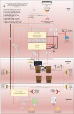
SwitchPro wiring diagram for loads

Since you asked about wire gauges, this is my wiring diagram for my SwitchPro aux electrical system. (There is no second battery at the moment.) It will give you some idea of wire gauges. For long runs to fridges, use 10 or 12 gauge (or heavier.) For lighting, 14 gauge (light bars) or 16 gauge (rock lights) works well. For each piece of gear, read the mfg specs, total up the amps, and use one of the online electrical calculators to find the best wire gauge for that circuit, then make sure it won't exceed the SwitchPro 20A or 35A circuit ratings. I absolutely love the SwitchPro 9100, by the way. Worth every penny.
 

Attachments

  • Wiring Diagram.jpg
    Wiring Diagram.jpg
    131 KB · Views: 4,285
Anyone know the dimensions for the Shrockworks battery tray? They don't list the dimensions on their website and haven't heard back from customer support. Reason I ask is I'm looking at retrofitting this tray into a 4th gen. Thank you
 
Anyone know the dimensions for the Shrockworks battery tray? They don't list the dimensions on their website and haven't heard back from customer support. Reason I ask is I'm looking at retrofitting this tray into a 4th gen. Thank you

I will measure mine later today, unless you already have had someone get you the info.
 

Members online

No members online now.

Forum statistics

Threads
278,316
Messages
3,554,120
Members
248,016
Latest member
Advally Service

Trending content

Back
Top