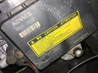
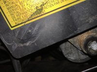
Are you sure that the crack wasn't there before? The scuffs/scratches I can't speak to, but you stated that you replaced it with a used unit earlier.
rwh963;3720103... they did say they rarely encounter this module failing (once per year). that's what the dealer said at 111k miles when the brake booster started squealing said:
replaced it with a used unit[/COLOR] and has run well for 120k miles; i believe that unit had 70k on it from salvage, so it has 190k on it now ...
In my experience used/junkyard parts are not gingerly removed, packaged, or shipped; we've constantly had to send back engines, transmissions, components from our junkyard because they do not take any care in removing them from the vehicle or prepping them for transport and they're not a small company.
I'm just playing devil's advocate here, the electrical testing the technician would have done should not have resulted in that crack to the module, not to mention that crack is filled with grime and dirt. Where it's located in the engine bay, that crack should be very clean and "shiny" looking if it's fresh (due to the fiber reinforcement it will sparkle a little).
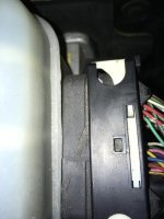
Now if you told me that the connector housing or the locking mechanism was broken I'd lean that on the technician (might not even be entirely his fault, those damn connectors are so crunchy and fragile after a decade that even your best efforts to clean/lube/and be gentle can still break them... just ask me how I know...

out: ).
~
Anyways, time to really dig into the entirety of the Stop Lamp Circuit and see if we can figure a better idea of what's going on now that we have some more information here. I will warn you guys, this is going to get technical, boring, and a bit wordy; but I think we're at the point of getting granular now, so no apologies on my end.
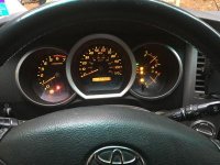
First and foremost, Have you been having ABS/VSC/TRAC/BRAKE warning lights turning on this entire time along with your brake lights? I was under the assumption that
only your brake lights were staying on by themselves and not that you also had ABS/VSC/TRAC/BRAKE warning lights on at the combination meter.
Reading over the technician's notes and reviewing the wiring diagram I posted earlier, their diagnostic process seems sound and their suspicion that the Skid Control ECU has failed internally sounds valid. Though there is two parts of their notes that seems a bit weird to me (granted, these repair order notes are often supposed to be as short as possible, so details get lost in translation), the technician states that they found the Skid Control ECU "back-feeding" voltage from the STPO wire causing the brake lights to remain on. I am wondering if that was a typo and they meant STP or STP2?
The reason I say that is because if you look at the wiring diagram the Stop Lamp Control Relay's control circuit (the magnetic coil side of the relay) is provided power via the Ignition Switch and is then grounded by the Skid Control ECU via the STPO pin thus turning the relay on. Voltage output on this pin shouldn't cause your concern, but back-fed battery voltage on the STP or STP2 pins/wires would cause your concern (STP & STP2 are signal inputs that the Skid Control ECU and other ECUs use to determine if and when the Stop Lamp Switch is closed and to activate the Stop Lamp Control Relay via the STPO pin and thus turn the brake lights on). The technician does state that they inspected the wiring and found no short to ground which implies that the circuit for the control side of the relay has no path to ground except for the STPO pin.
The second thing that seems a bit weird to me due to lack of proper context/detail is the technician states "Removed STPO wire from ABS Actuator and then checked brake switch operation, OK". I am not entirely sure what they mean by "Removed STPO wire," it could mean they had the ABS Connector removed or possibly they de-pinned the wire from the connector (which seems more useful, so we'll go with that?) De-pinning the STPO wire would disable the ability of the Skid Control ECU from turning the Stop Lamp Control Relay on itself, so I wouldn't expect that de-pinning the STPO wire would affect the brake switch side of things besides set a DTC. I would be more curious what de-pinning STP and STP2 does and measuring voltage on those circuits without activating the brake switch as they should have 0 volts on them until the switch is activated. Unfortunately as I mentioned above, these repair order notes tend to get really simplified, vague, and sometimes weirdly translated (i.e. a service writer might take what the technician said and "dumb it down" for the customer) and so I wouldn't use this as anything more than a rough idea of what was done.
Something to note here is that the Stop Lamp Control Relay is
not needed for the function of the brake lights nor for the direct function of the ABS/VSC/TRAC systems (though removing it will set a C1380 DTC). What the relay does is provide brake switch information (STP On/Off & STP2 On/Off Inputs) to various ECUs for the purposes of adjusting electrical load & signaling to an
optional 3rd party Towing Brake Controller that the brake pedal has been pressed so that it can command the Towing Converter Relay to close and provide additional current on the brake light switch that would over-load the factory Stop Lamp circuit (a bit of paraphrasing on my part, but for our diagnostic purposes this is what it does). I was scratching my head for a little bit when I was digging deeper into the function of this circuit as a whole because it didn't make sense to me
why the relay existed in the first place. The relay was added to the Stop Lamp Circuit in 3rd Gen 4Runners from 2001-2002 when they got the newer hydraulic brake booster and was retained for all following models. Double checking a similar model Camry, Corolla, and Highlander I found that the two cars do not use a Stop Lamp Control Relay and retain a simple Brake Switch activated system, while the Highlander does use a relay. In the Highlander's case the wiring is a bit different because unlike the 4Runner and similar Toyota trucks, the Highlander does not have a "Plug & Play" option for 3rd party Towing Brake Controllers; instead there is an integrated trailer converter that is used.
~
Final thoughts:
-I think the technician might be right that the Skid Control ECU may be failing internally and either back feeding voltage when it's not supposed to via the STP and STP2 pins or it is commanding the Stop Lamp Control Relay on when it shouldn't be.
-STPO is a ground-operated ECU output, meaning that the Skid Control ECU grounds that pin to turn the relay on, de-pinning the wire from the ABS Connector should rule that out (which it seems the technician did during their diagnosis).
-I would de-pin both STP & STP2 from the ABS connector and with the vehicle turned on and the brake pedal not depressed check STP & STP2 pins out of the Skid Control ECU for voltage, there should be 0 volts from those pins as STP & STP2 are voltage inputs meaning that the Skid Control ECU is looking for voltage coming in from the circuit and it is not producing a signal itself; if there is voltage coming out of the Skid Control ECU on those pins under the mentioned conditions, then it's likely the Skid Control ECU has failed internally. Additionally there should be 0 volts on the STP & STP2 wires under the same vehicle on, brake pedal not depressed conditions; if there is voltage on these wires under those conditions, there is a short to power somewhere back-feeding voltage into the circuit and could be your issue.
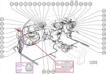
-If there is a short to power on the circuit after the Stop Lamp Control Relay side of the circuit, then I would look at Junction Connector J4 next, many of the wires go through this junction connector and it would be worth testing this connector next. This is a connector that doesn't seem too easy to get to, it's located just above the main harness after it routes through the firewall; but it's location and it's frequent use in this circuit makes it a top suspect in my book at this point. It is located close enough to the firewall and just under the windshield that it's possible if water was leaking/had leaked into the vehicle along that area in the past it could have caused corrosion to short multiple portions of that junction connector together. Note- it will look like it has a "dummy" connector plugged into it, that "dummy" connector is the junction bus bar and has small metal plates in it to distribute power for the multiple circuits.
-Another possible culprit for a short to power could be the Towing Brake Controller connector (Connector T6), again possibly due to corrosion causing a short between the pins, this guy is easier to locate and is found behind the driver's left kick panel; it won't be connected to anything.
-If you don't find any short to power or leaking voltage at those areas and it's still present, there's some sort of damage or corrosion somewhere in the harness; tracing it down is going to be very tedious and time-consuming (or if someone else is diagnosing it, very expensive).
~
I went ahead attached some files for you:
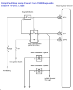
-A simplified Stop Lamp Circuit that I pulled from the C1380 diagnostic steps section of the FSM. I find this easier to use for visualizing how power flows from the battery to the lights themselves than the Overall Wiring Diagram.
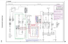
-An unmolested Overall Wiring Diagram of the entire Stop Lamp circuit (this one is more in depth and shows a bit more detail on one page than the EWD page I gave you earlier)
-An Annotated version of the Overall Wiring Diagram with my notes on the sections of the circuit, where I think some good starting diagnosis points would be based on where you're at now and some clarifications that should help you visualize what I was saying earlier in the post.
-A Connector Location page that I annotated showing the locations of the J4 Junction Connector and T6 Trailer Brake Controller Connector as well as their colors if you wanted to track them down yourself.
I hope this helps you find a resolution to such a weird issue! This was a bit of a time sink, I didn't realize I've been working on this post for 3 hours now! :rip: But this is basically everything I can think of based on the information you provided and the information I have available to me.