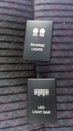
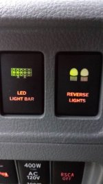
For those of you who can’t stand green illumination light that come with these aftermarket switches, and want to match your amber dash lights, here’s what I did.
First, difficulty: Disassembly/assembly of switch – easy (no springs or contact to fiddle with). Replacing LED light: moderate, but not difficult (experience soldering recommended)
Tools required: Soldering iron, solder, small (blade) screw driver, wire cutters, and a file
Replacement Amber 5mm LED (no resistor required)
View attachment 124127
1. With switch in off position, insert screw driver into slot (red arrow) with a slight twist tab will release, repeat on opposite side. Rear alignment tabs are angled so no need to do anything, just lift straight up and remove cover. Now gently lift up on rear edge of circuit board (plug end), lift just high enough so circuit board is above notch of switch housing (yellow arrow).
View attachment 124128
2. Remove wiring harness plug insert (just slides out). On insert (picture shows circuit board side) you will notice a tab, tab lines up with alignment hole in circuit board.
View attachment 124131
3. Gently slide circuit board rearward until push button face contacts housing. You will notice square yellow plunger is seated in square plastic area of push button face (indicated by red arrow). Wiggle circuit board slightly while lifting straight up and yellow plunger will slide right out. Picture below shows circuit board unclipped from face to better show what I’m talking about.
View attachment 124132
4. We will be replacing the clear LED indicated by black arrow (also, notice circuit board already has resistors). After much searching, I was unable source an exact replacement LED, so I went to a local electronic shop who had two different round LED’s (3mm, 5mm) in amber. I choose the 5mm because it was slightly brighter, but knew it was going to be a tight fit. I also wasn’t sure how bright this choice was going to be since stock one was super bright, but what the heck…………..
If you want to change color of the switch “on” indicator, you could follow the same procedure and replace the upper green 3mm LED.
View attachment 124133
5. De-solder clear LED and remove, remove any excess solder from board. Take new LED and bend leads 90 degrees. Make sure you keep polarity the same, positive to positive, negative to negative. Insert leads through circuit board holes and solder. **Caution should be taken not to allow solder from positive lead to contact negative lead. Take wire cutters and trim excess leads so they are flush with the other solder joints on board.
View attachment 124134
View attachment 124135
6. Amber LED installed. Two items to note, LED is touching metal housing of switch, second file lip off LED where black arrow is pointing. Space is tight, filing edge of LED (only on the circuit board outboard side) will allow just enough clearance that when switch is reassembled it will not bind or stick when turning on & off. Next, bend LED upward to match angle of green LED. Now is a good time to test our mod before reassembly, plug in harness and turn on parking lights, amber LED should illuminate! If not, check LED polarity or solder joints for good connections.
View attachment 124136
7. If all is good, reassembly time. Once switch is reassembled, depress switch multiple times to verify it turns on & off without any binding or sticking. Plug in harness, insert into dash opening, all done.
I was concerned that the amber color wouldn’t match factory dash lights or they wouldn’t be bright enough, but I was pleasantly surprised, they match the factory switches perfectly. BTW, sorry for the crappy cell phone pictures.



 imp:
imp:


 . So the hunt was on for a factory style switch that would replace my two blank spots in dash. After conducting multiple searches both here and online for several months, two things became apparent. Toyota doesn’t make a fog light switch (that we can get in the US) that fits. I tried the FJ switch, but it didn’t fit without having to cut dash which I didn’t want to do, my search was going to be a difficult. Wasn’t really iterested in OTRATTW switches which I’m sure are awesome, like I said, want that stock look.